2006 SUZUKI SX4 battery
[x] Cancel search: batteryPage 1016 of 1556
Downloaded from www.Manualslib.com manuals search engine 7B-76 Air Conditioning System: Automatic Type
Inspection of HVAC Control Module and Its CircuitS6RW0D7224029
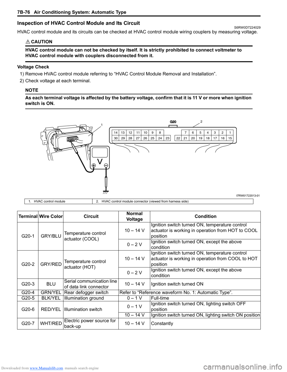
HVAC control module and its circuits can be checked at HVAC control module wiring couplers by measuring voltage.
CAUTION!
HVAC control module can not be checked by itself. It is strictly prohibited to connect voltmeter to
HVAC control module with couplers disconnected from it.
Voltage Check
1) Remove HVAC control module referring to “HVAC Control Module Removal and Installation”.
2) Check voltage at each terminal.
NOTE
As each terminal voltage is affected by the battery voltage, confirm that it is 11 V or more when ignition
switch is ON.
G20
1 2 3 4 5 6 7 8 9 10 11 12 13 14
15 16 17 18 19 20 21 24 23 22 25 26 27 28 29 30
12
I7RW01722013-01
1. HVAC control module 2. HVAC control module connector (viewed from harness side)
Terminal Wire Color CircuitNormal
Vo l ta g eCondition
G20-1 GRY/BLUTemperature control
actuator (COOL)10 – 14 VIgnition switch turned ON, temperature control
actuator is working in operation from HOT to COOL
position
0 – 2 VIgnition switch turned ON, except the above
condition
G20-2 GRY/REDTemperature control
actuator (HOT)10 – 14 VIgnition switch turned ON, temperature control
actuator is working in operation from COOL to HOT
position
0 – 2 VIgnition switch turned ON, except the above
condition
G20-3 BLUSerial communication line
of data link connector10 – 14 V Ignition switch turned ON
G20-4 GRN/YEL Rear defogger switchRefer to “Reference waveform No. 1: Automatic Type”.
G20-5 BLK/YEL Illumination ground 0 – 1 V Full-time
G20-6 RED/YEL Illumination switch0 – 1 VIgnition switch turned ON, lighting switch OFF
position
10 – 14 V Ignition switch turned ON, lighting switch ON position
G20-7 WHT/REDElectric power source for
back-up10 – 14 V Constantly
Page 1021 of 1556
Downloaded from www.Manualslib.com manuals search engine Air Conditioning System: Automatic Type 7B-81
HVAC Unit Removal and InstallationS6RW0D7226003
Refer to “HVAC Unit Removal and Installation”.
Temperature Control Actuator Removal and
Installation
S6RW0D7226004
Removal
1) Disconnect negative (–) cable at battery.
2) Remove steering column hole cover from instrument
panel.
3) Remove driver side foot duct from HVAC unit.
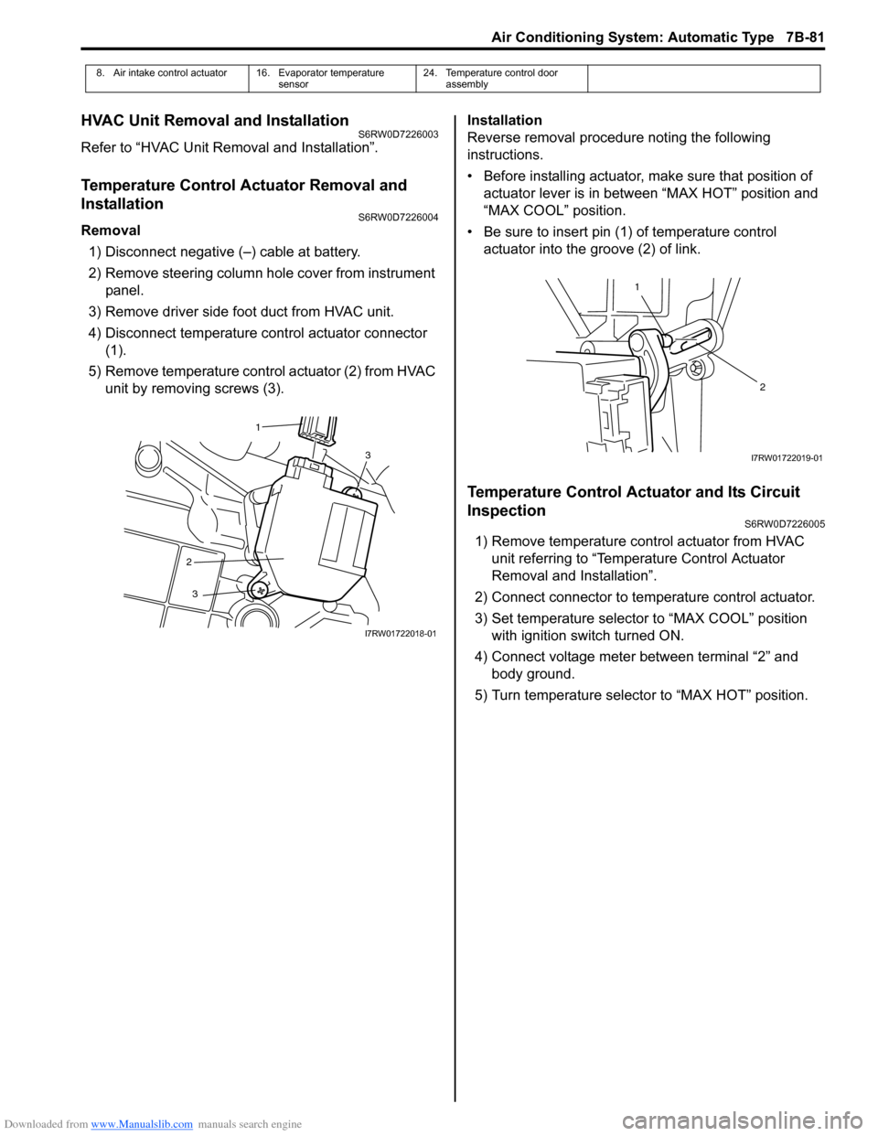
4) Disconnect temperature control actuator connector
(1).
5) Remove temperature control actuator (2) from HVAC
unit by removing screws (3).Installation
Reverse removal procedure noting the following
instructions.
• Before installing actuator, make sure that position of
actuator lever is in between “MAX HOT” position and
“MAX COOL” position.
• Be sure to insert pin (1) of temperature control
actuator into the groove (2) of link.
Temperature Control Actuator and Its Circuit
Inspection
S6RW0D7226005
1) Remove temperature control actuator from HVAC
unit referring to “Temperature Control Actuator
Removal and Installation”.
2) Connect connector to temperature control actuator.
3) Set temperature selector to “MAX COOL” position
with ignition switch turned ON.
4) Connect voltage meter between terminal “2” and
body ground.
5) Turn temperature selector to “MAX HOT” position.
8. Air intake control actuator 16. Evaporator temperature
sensor24. Temperature control door
assembly
3
2
3
1
I7RW01722018-01
1
2
I7RW01722019-01
Page 1023 of 1556
Downloaded from www.Manualslib.com manuals search engine Air Conditioning System: Automatic Type 7B-83
Air Flow Control Actuator Removal and
Installation
S6RW0D7226006
Removal
1) Disconnect negative cable at battery.
2) Remove steering column hole cover from instrument
panel.
3) Remove driver side foot duct from HVAC unit.
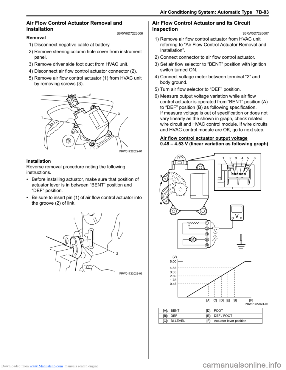
4) Disconnect air flow control actuator connector (2).
5) Remove air flow control actuator (1) from HVAC unit
by removing screws (3).
Installation
Reverse removal procedure noting the following
instructions.
• Before installing actuator, make sure that position of
actuator lever is in between “BENT” position and
“DEF” position.
• Be sure to insert pin (1) of air flow control actuator into
the groove (2) of link.
Air Flow Control Actuator and Its Circuit
Inspection
S6RW0D7226007
1) Remove air flow control actuator from HVAC unit
referring to “Air Flow Control Actuator Removal and
Installation”.
2) Connect connector to air flow control actuator.
3) Set air flow selector to “BENT” position with ignition
switch turned ON.
4) Connect voltage meter between terminal “2” and
body ground.
5) Turn air flow selector to “DEF” position.
6) Measure output voltage variation while air flow
control actuator is operated from “BENT” position (A)
to “DEF” position (B) as following specification.
If measure voltage is out of specification or does not
vary linearly as the shown in graph, check related
wire circuit and HVAC control module. If wire circuits
and HVAC control module are OK, go to next step.
Air flow control actuator output voltage
0.48 – 4.53 V (linear variation as following graph)
13
2
I7RW01722022-01
1
2
I7RW01722023-02
[A]: BENT [D]: FOOT
[B]: DEF [E]: DEF / FOOT
[C]: BI-LEVEL [F]: Actuator lever position
123456
6
M5
3
2
1 A
B
(V)
4.53
3.35
2.60
1.78
0.48
[A][B]
[C] [D] [E][F]5.00
I7RW01722024-02
Page 1025 of 1556
Downloaded from www.Manualslib.com manuals search engine Air Conditioning System: Automatic Type 7B-85
Blower Motor Controller InspectionS6RW0D7226012
1) Check internal circuit of controller for resistance as
follows.
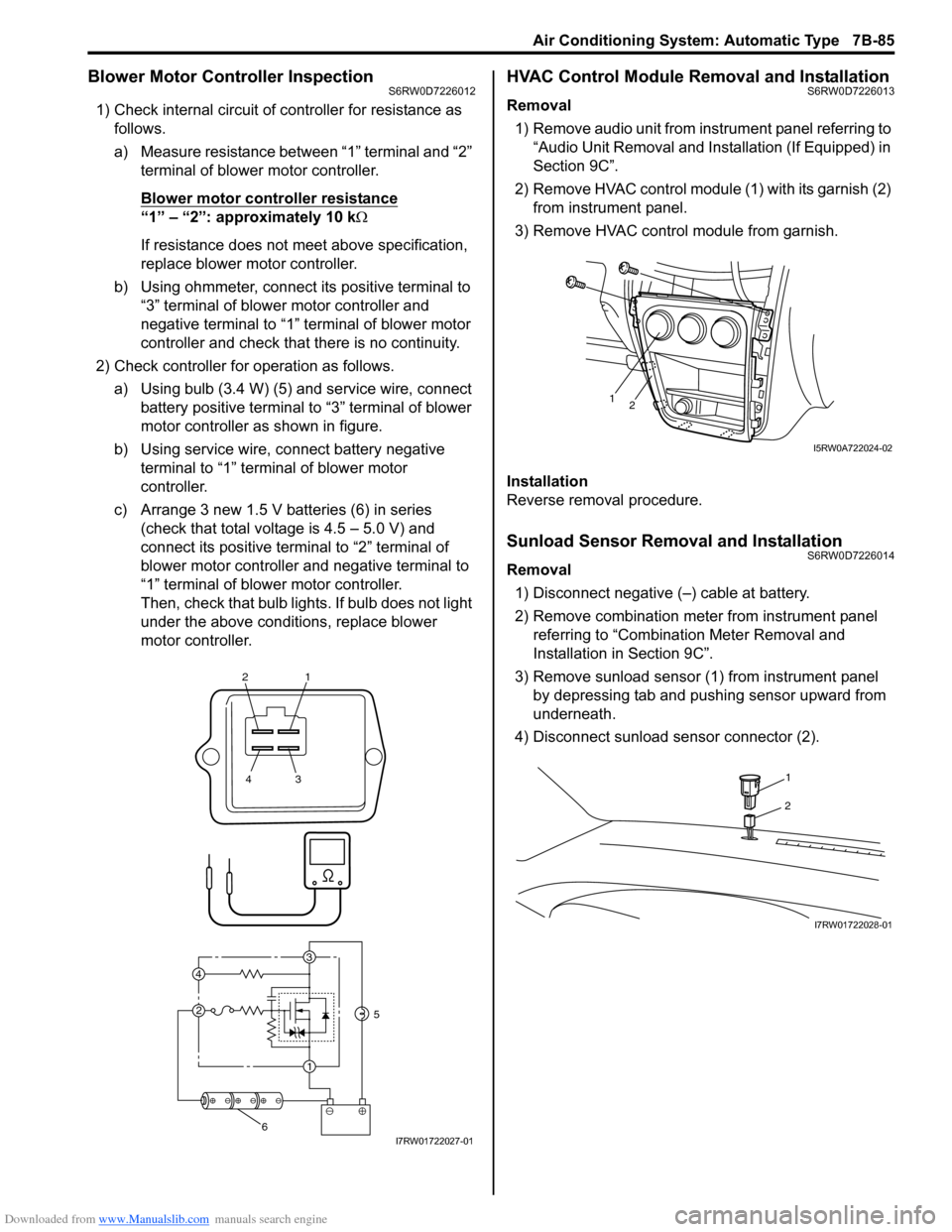
a) Measure resistance between “1” terminal and “2”
terminal of blower motor controller.
Blower motor controller resistance
“1” – “2”: approximately 10 kΩ
If resistance does not meet above specification,
replace blower motor controller.
b) Using ohmmeter, connect its positive terminal to
“3” terminal of blower motor controller and
negative terminal to “1” terminal of blower motor
controller and check that there is no continuity.
2) Check controller for operation as follows.
a) Using bulb (3.4 W) (5) and service wire, connect
battery positive terminal to “3” terminal of blower
motor controller as shown in figure.
b) Using service wire, connect battery negative
terminal to “1” terminal of blower motor
controller.
c) Arrange 3 new 1.5 V batteries (6) in series
(check that total voltage is 4.5 – 5.0 V) and
connect its positive terminal to “2” terminal of
blower motor controller and negative terminal to
“1” terminal of blower motor controller.
Then, check that bulb lights. If bulb does not light
under the above conditions, replace blower
motor controller.
HVAC Control Module Removal and InstallationS6RW0D7226013
Removal
1) Remove audio unit from instrument panel referring to
“Audio Unit Removal and Installation (If Equipped) in
Section 9C”.
2) Remove HVAC control module (1) with its garnish (2)
from instrument panel.
3) Remove HVAC control module from garnish.
Installation
Reverse removal procedure.
Sunload Sensor Removal and InstallationS6RW0D7226014
Removal
1) Disconnect negative (–) cable at battery.
2) Remove combination meter from instrument panel
referring to “Combination Meter Removal and
Installation in Section 9C”.
3) Remove sunload sensor (1) from instrument panel
by depressing tab and pushing sensor upward from
underneath.
4) Disconnect sunload sensor connector (2).
21
43
3
1 2 4
5
6I7RW01722027-01
12
I5RW0A722024-02
1
2
I7RW01722028-01
Page 1026 of 1556
Downloaded from www.Manualslib.com manuals search engine 7B-86 Air Conditioning System: Automatic Type
Installation
Reverse removal procedure noting the following
instructions.
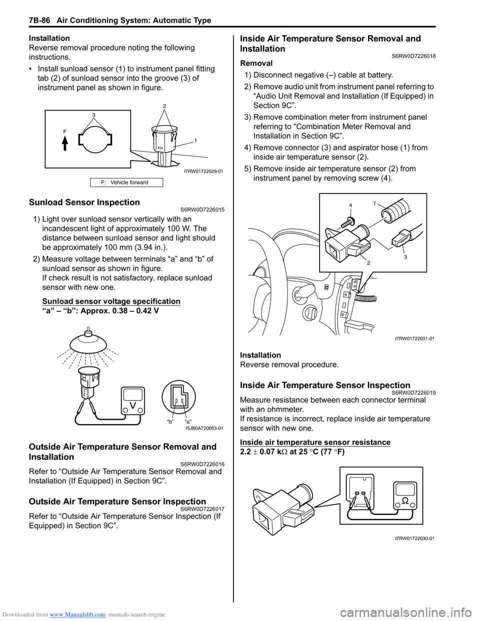
• Install sunload sensor (1) to instrument panel fitting
tab (2) of sunload sensor into the groove (3) of
instrument panel as shown in figure.
Sunload Sensor InspectionS6RW0D7226015
1) Light over sunload sensor vertically with an
incandescent light of approximately 100 W. The
distance between sunload sensor and light should
be approximately 100 mm (3.94 in.).
2) Measure voltage between terminals “a” and “b” of
sunload sensor as shown in figure.
If check result is not satisfactory, replace sunload
sensor with new one.
Sunload sensor voltage specification
“a” – “b”: Approx. 0.38 – 0.42 V
Outside Air Temperature Sensor Removal and
Installation
S6RW0D7226016
Refer to “Outside Air Temperature Sensor Removal and
Installation (If Equipped) in Section 9C”.
Outside Air Temperature Sensor InspectionS6RW0D7226017
Refer to “Outside Air Temperature Sensor Inspection (If
Equipped) in Section 9C”.
Inside Air Temperature Sensor Removal and
Installation
S6RW0D7226018
Removal
1) Disconnect negative (–) cable at battery.
2) Remove audio unit from instrument panel referring to
“Audio Unit Removal and Installation (If Equipped) in
Section 9C”.
3) Remove combination meter from instrument panel
referring to “Combination Meter Removal and
Installation in Section 9C”.
4) Remove connector (3) and aspirator hose (1) from
inside air temperature sensor (2).
5) Remove inside air temperature sensor (2) from
instrument panel by removing screw (4).
Installation
Reverse removal procedure.
Inside Air Temperature Sensor InspectionS6RW0D7226019
Measure resistance between each connector terminal
with an ohmmeter.
If resistance is incorrect, replace inside air temperature
sensor with new one.
Inside air temperature sensor resistance
2.2 ± 0.07 kΩ at 25 °C (77 °F)
F: Vehicle forward
2
F
1
3
I7RW01722029-01
“b” “a”I5JB0A720053-01
1
23 4
I7RW01722031-01
I7RW01722030-01
Page 1028 of 1556
Downloaded from www.Manualslib.com manuals search engine 7B-88 Air Conditioning System: Automatic Type
Special Tools and Equipment
Recommended Service MaterialS6RW0D7228001
NOTE
Required service material is also described in the following.
“HVAC Unit Components”
Special ToolS6RW0D7228002
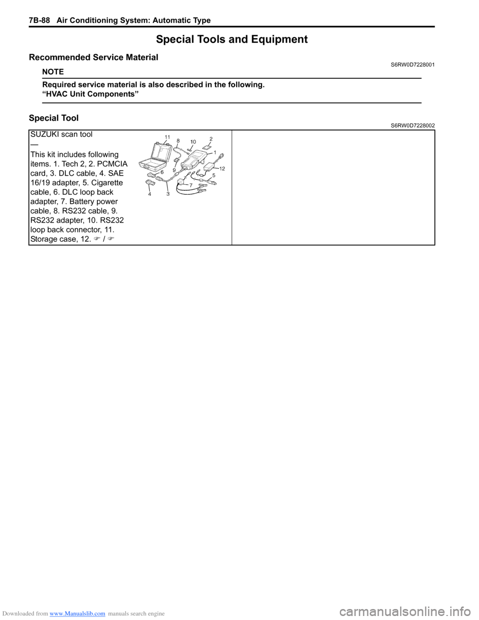
SUZUKI scan tool
—
This kit includes following
items. 1. Tech 2, 2. PCMCIA
card, 3. DLC cable, 4. SAE
16/19 adapter, 5. Cigarette
cable, 6. DLC loop back
adapter, 7. Battery power
cable, 8. RS232 cable, 9.
RS232 adapter, 10. RS232
loop back connector, 11.
Storage case, 12. �) / �)
Page 1036 of 1556
Downloaded from www.Manualslib.com manuals search engine 8A-5 Seat Belts:
Front Seat Belt Removal and InstallationS6RW0D8106002
WARNING!
• Never attempt to disassemble or repair the
retractor (seat belt pretensioner). If any
abnormality is found, be sure to replace it
with new one as an assembly.
• Be sure to read “Precautions on Service
and Diagnosis of Seat Belt” before starting
to work and observe every precaution
during work. Neglecting them may result in
personal injury or unactivation of the seat
belt pretensioner when necessary.
Removal
1) Disconnect negative (–) cable at battery.
2) Disable air bag system. Refer to “Disabling Air Bag
System in Section 8B”.
3) Remove center pillar lower trim.
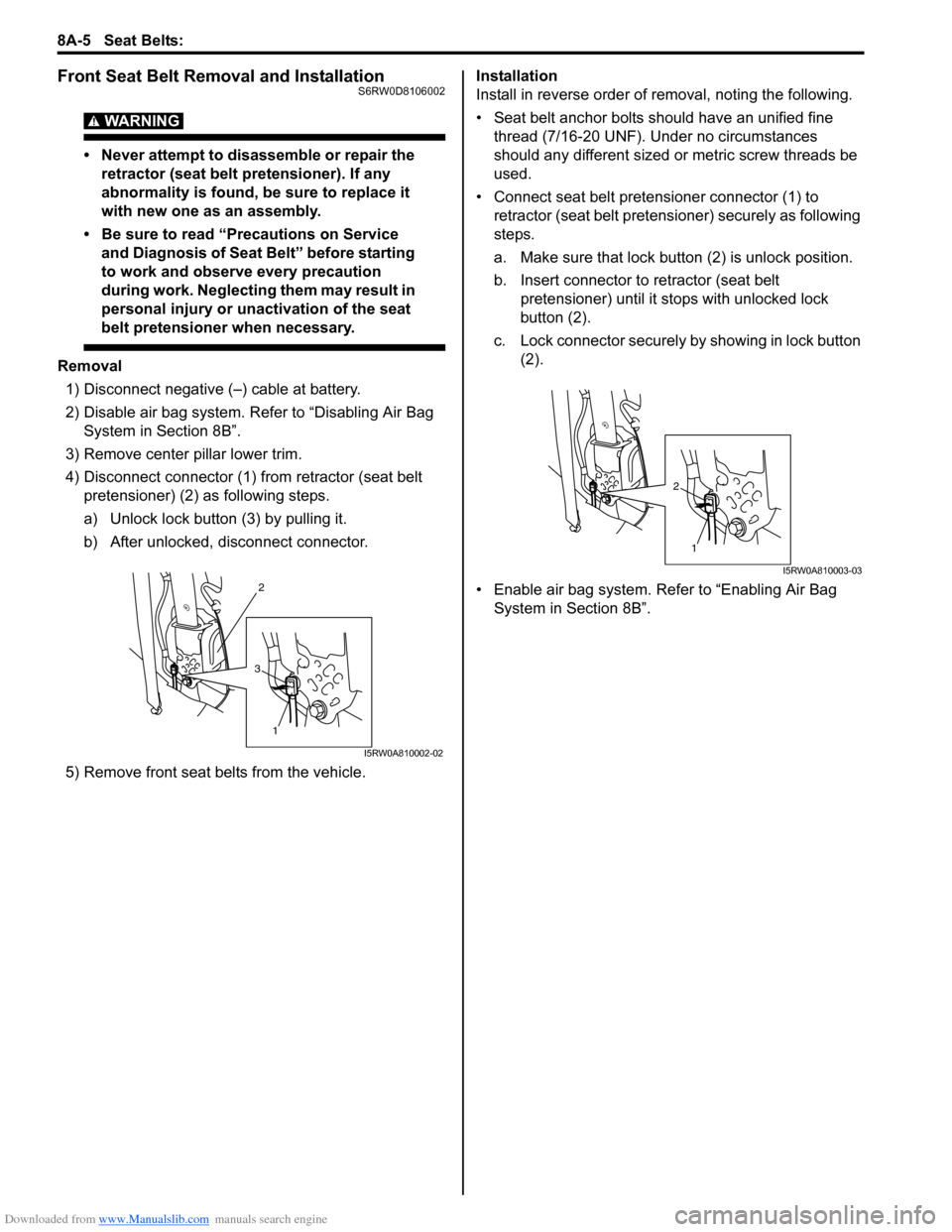
4) Disconnect connector (1) from retractor (seat belt
pretensioner) (2) as following steps.
a) Unlock lock button (3) by pulling it.
b) After unlocked, disconnect connector.
5) Remove front seat belts from the vehicle.Installation
Install in reverse order of removal, noting the following.
• Seat belt anchor bolts should have an unified fine
thread (7/16-20 UNF). Under no circumstances
should any different sized or metric screw threads be
used.
• Connect seat belt pretensioner connector (1) to
retractor (seat belt pretensioner) securely as following
steps.
a. Make sure that lock button (2) is unlock position.
b. Insert connector to retractor (seat belt
pretensioner) until it stops with unlocked lock
button (2).
c. Lock connector securely by showing in lock button
(2).
• Enable air bag system. Refer to “Enabling Air Bag
System in Section 8B”.
2
1
3
I5RW0A810002-02
1
2
I5RW0A810003-03
Page 1045 of 1556
Downloaded from www.Manualslib.com manuals search engine Air Bag System: 8B-6
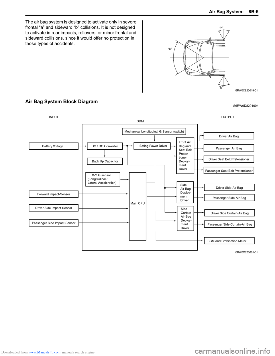
The air bag system is designed to activate only in severe
frontal “a” and sideward “b” collisions. It is not designed
to activate in rear impacts, rollovers, or minor frontal and
sideward collisions, since it would offer no protection in
those types of accidents.
Air Bag System Block DiagramS6RW0D8201004
I6RW0C820019-01
Battery Voltage
Forward Impact-Sensor
Driver Side Impact-Sensor
Passenger Side Impact-Sensor
DC / DC Converter
Back Up Capacitor
Safing Power Driver
Mechanical Longitudinal G Sensor (switch)
X-Y G sensor
(Longitudinal /
Lateral Acceleration)
Driver Side-Air Bag
Driver Side Curtain-Air Bag
Passenger Side Curtain-Air Bag
Passenger Side-Air Bag
Passenger Seat Belt Pretensioner
Driver Seat Belt Pretensioner
Passenger Air Bag
Driver Air Bag
INPUTOUTPUTSDM
Front Air
Bag and
Seat Belt
Preten-
tioner
Deploy-
ment
Driver
Side
Air Bag
Deploy-
ment
Driver
Side
Curtain
Air Bag
Deploy-
ment
Driver
Main CPU
BCM and Cmbination Meter
I6RW0C820001-01