2006 SUZUKI SX4 accessories
[x] Cancel search: accessoriesPage 1167 of 1556
Downloaded from www.Manualslib.com manuals search engine Precautions: 9-1
Body, Cab and Accessories
Precautions
Precautions
Precautions on Body, Cab and AccessoriesS6RW0D9000001
Air Bag Warning
Refer to “Air Bag Warning in Section 00”.
Fastener Caution
Refer to “Fastener Caution in Section 00”.
Precautions for Body Service
Refer to “Precautions for Body Service”.
Fastener Caution for Body Service:
Refer to “Fastener Caution for Body Service”.
Cautions in Body Electrical System Servicing
Refer to “Cautions in Body Electrical System Servicing in Section 9A”.
Precautions for Discharge Headlight Service (If Equipped)
Refer to “Precautions for Discharge Headlight Service (If Equipped) in Section 9B”.
Precautions for Power Window Service (Pinching Prevention Function Model)
Refer to “Precautions for Power Window Service (Pinching Prevention Function Model) in Section 9E”.
Precautions for Body ServiceS6RW0D9000002
WARNING!
For vehicles equipped with a Supplemental Restraint (Air Bag) System:
When servicing vehicle body, if shock may be applied to air bag system component parts, remove
those parts beforehand.
Fastener Caution for Body ServiceS6RW0D9000003
CAUTION!
• Fasteners are important attaching parts in that they could affect the performance of vital
components and systems, and/or could result in major repair expense. They must be replaced with
one of the same part number of with an equivalent part if replacement become necessary.
• Do not use a replacement part of lesser quality or substitute a design. Torque values must be used
as specified during reassembly to assure proper retention of these parts.
Page 1168 of 1556
Downloaded from www.Manualslib.com manuals search engine 9A-1 Wiring Systems:
Body, Cab and Accessories
Wiring Systems
Precautions
Cautions in Body Electrical System ServicingS6RW0D9100001
When servicing the electric systems, observe the cautions described in “Air Bag Warning in Section 00” to protect
electrical parts and to prevent a fire.
General Description
AbbreviationsS6RW0D9101001
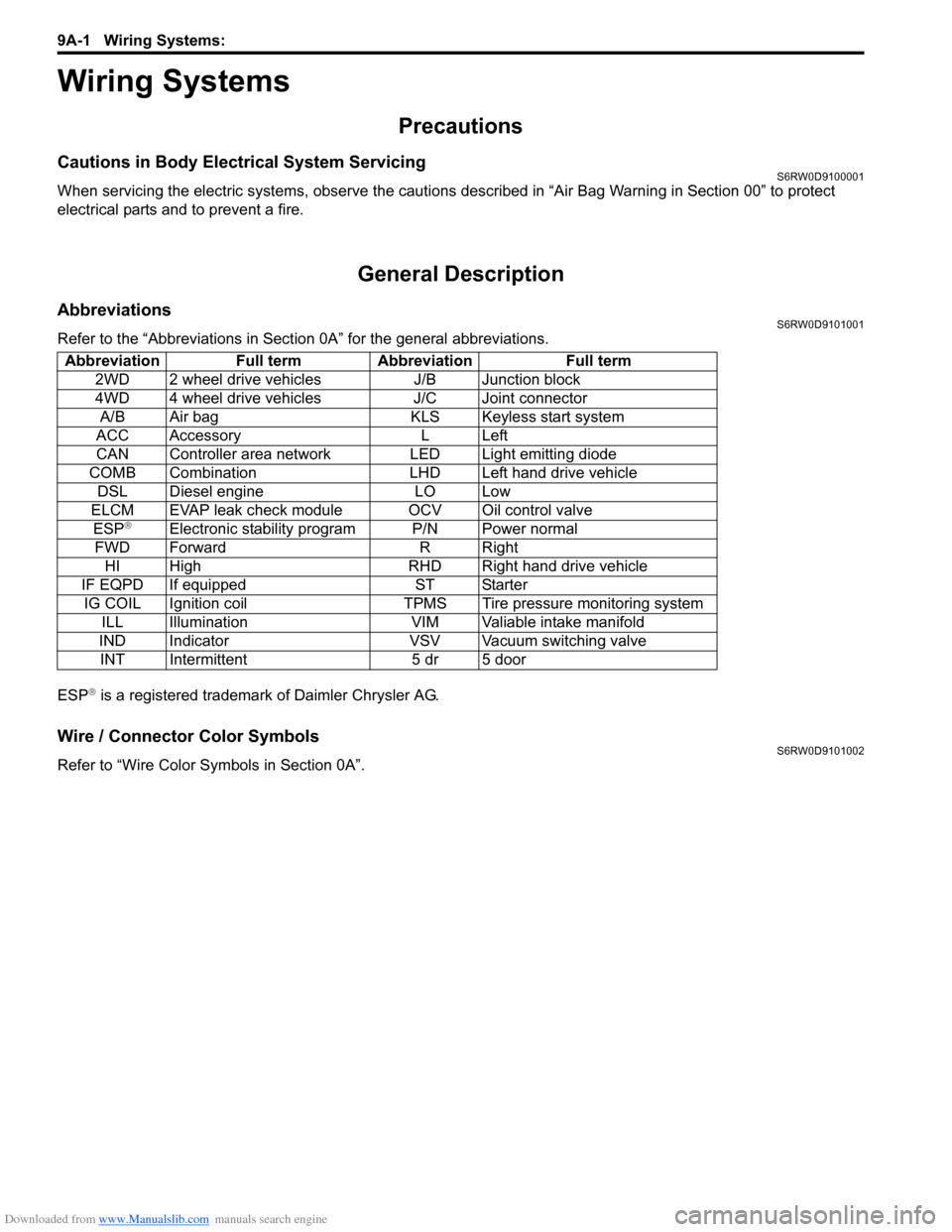
Refer to the “Abbreviations in Section 0A” for the general abbreviations.
ESP
® is a registered trademark of Daimler Chrysler AG.
Wire / Connector Color SymbolsS6RW0D9101002
Refer to “Wire Color Symbols in Section 0A”. Abbreviation Full term Abbreviation Full term
2WD 2 wheel drive vehicles J/B Junction block
4WD 4 wheel drive vehicles J/C Joint connector
A/B Air bag KLS Keyless start system
ACC Accessory L Left
CAN Controller area network LED Light emitting diode
COMB Combination LHD Left hand drive vehicle
DSL Diesel engine LO Low
ELCM EVAP leak check module OCV Oil control valve
ESP
®Electronic stability program P/N Power normal
FWD Forward R Right
HI High RHD Right hand drive vehicle
IF EQPD If equipped ST Starter
IG COIL Ignition coil TPMS Tire pressure monitoring system
ILL Illumination VIM Valiable intake manifold
IND Indicator VSV Vacuum switching valve
INT Intermittent 5 dr 5 door
Page 1320 of 1556
Downloaded from www.Manualslib.com manuals search engine 9B-1 Lighting Systems:
Body, Cab and Accessories
Lighting Systems
Precautions
Precautions for Discharge Headlight Service (If Equipped)S6RW0D9200001
WARNING!
• Do not touch igniter or ballast when lighting switch is at “HEAD” position to avoid possible electric
shock.
• Do not measure voltage or resistance with tester connected to output connector of ballast or igniter
to avoid possible electric shock.
• Do not perform work where exposed to water including rain or with wet hands to avoid possible
electric shock.
• Disassembling igniter or ballast is strictly prohibited as it may cause an electric shock.
• Before inspecting or repairing discharge headlight or its peripheral parts, make sure that lighting
switch is at OFF position and battery is disconnected at negative terminal to avoid possible
electrical shock.
• Do not set lighting switch to “HEAD” position with connector disconnected or any part removed to
avoid possible electric shock.
• Do not touch glass surface of headlight bulb. Oil or grease attached on it may not only make bulb
service life shorter but also cause bulb to burst when lighting switch is turned on.
• Mercury, metal iodide and xenon gas are sealed in discharge headlight bulb. Be sure to dispose of
used discharge headlight bulb properly according to applicable rules or regulations.
Precautions in Diagnosing Troubles (Headlight Auto Leveling System)S6RW0D9200002
• Be sure to read “Air Bag Warning in Section 00” before inspection and observe what is written there.
• Replacement of height sensor and headlight leveling control module. When height sensor and/or headlight leveling
control module is replaced with new one, perform initialization of headlight auto leveling system according to
“Initialization of Headlight Auto Leveling System”.
General Description
Discharge Headlight Description (If Equipped)S6RW0D9201001
Discharge headlight provides more brightness and consumes less electricity as compared with the conventional
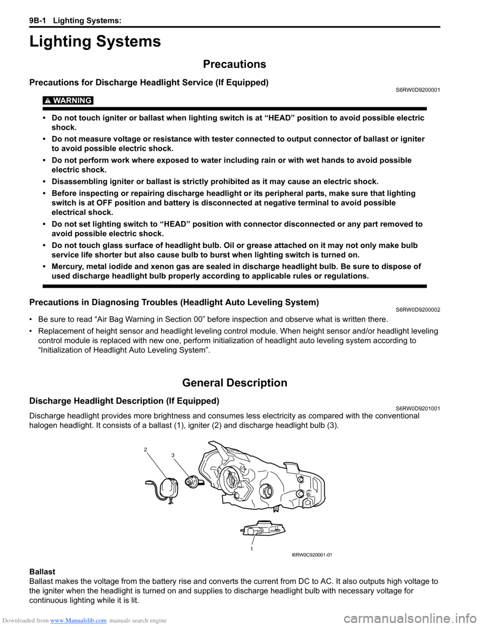
halogen headlight. It consists of a ballast (1), igniter (2) and discharge headlight bulb (3).
Ballast
Ballast makes the voltage from the battery rise and converts the current from DC to AC. It also outputs high voltage to
the igniter when the headlight is turned on and supplies to discharge headlight bulb with necessary voltage for
continuous lighting while it is lit.
2
1 3
I6RW0C920001-01
Page 1353 of 1556
Downloaded from www.Manualslib.com manuals search engine Instrumentation / Driver Info. / Horn: 9C-1
Body, Cab and Accessories
Instrumentation / Driver Info. / Horn
Precautions
Precautions in Diagnosing Troubles for Combination MeterS6RW0D9300001
Combination meter uses signals (information) from each control module by CAN communication to control
speedometer, tachometer, fuel meter, engine coolant temp meter, warning light and indicator light (other than air bag
warning light, EPS warning light, headlight leveling warning light (if equipped), rear fog light indicator light (if
equipped), high beam indicator light and turn signal indicator light). Therefor, check that no DTC is detected in each
module before performing combination meter symptom diagnosis. If any DTC is detected, correct trouble indicated by
that DTC troubleshooting first.
General Description
CAN Communication System DescriptionS6RW0D9301001
Refer to “CAN Communication System Description in Section 1A” for CAN communication system description.
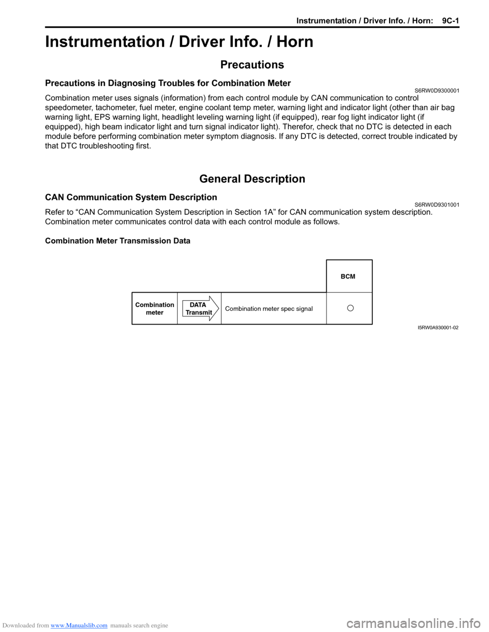
Combination meter communicates control data with each control module as follows.
Combination Meter Transmission Data
BCM
Combination
meterDATA
TransmitCombination meter spec signal
I5RW0A930001-02
Page 1375 of 1556
Downloaded from www.Manualslib.com manuals search engine Wipers / Washers: 9D-1
Body, Cab and Accessories
Wipers / Washers
Diagnostic Information and Procedures
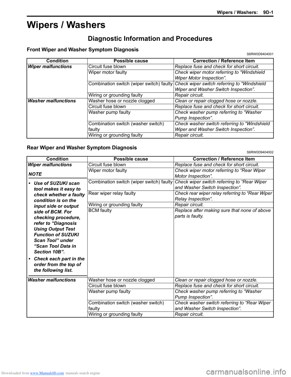
Front Wiper and Washer Symptom DiagnosisS6RW0D9404001
Rear Wiper and Washer Symptom DiagnosisS6RW0D9404002
Condition Possible cause Correction / Reference Item
Wiper malfunctionsCircuit fuse blownReplace fuse and check for short circuit.
Wiper motor faultyCheck wiper motor referring to “Windshield
Wiper Motor Inspection”.
Combination switch (wiper switch) faultyCheck wiper switch referring to “Windshield
Wiper and Washer Switch Inspection”.
Wiring or grounding faultyRepair circuit.
Washer malfunctionsWasher hose or nozzle cloggedClean or repair clogged hose or nozzle.
Circuit fuse blownReplace fuse and check for short circuit.
Washer pump faultyCheck washer pump referring to “Washer
Pump Inspection”.
Combination switch (washer switch)
faultyCheck washer switch referring to “Windshield
Wiper and Washer Switch Inspection”.
Wiring or grounding faultyRepair circuit.
Condition Possible cause Correction / Reference Item
Wiper malfunctions
NOTE
• Use of SUZUKI scan
tool makes it easy to
check whether a faulty
condition is on the
input side or output
side of BCM. For
checking procedure,
refer to “Diagnosis
Using Output Test
Function of SUZUKI
Scan Tool” under
“Scan Tool Data in
Section 10B”.
• Check each part in the
order from the top of
the following list.
Circuit fuse blownReplace fuse and check for short circuit.
Wiper motor faultyCheck wiper motor referring to “Rear Wiper
Motor Inspection”.
Combination switch (wiper switch) faultyCheck wiper switch referring to “Rear Wiper
and Washer Switch Inspection”.
Rear wiper relay faultyCheck rear wiper relay referring to “Rear Wiper
Relay Inspection”.
Wiring or grounding faultyRepair circuit.
BCM faultyReplace after making sure that none of above
parts is faulty.
Washer malfunctionsWasher hose or nozzle cloggedClean or repair clogged hose or nozzle.
Circuit fuse blownReplace fuse and check for short circuit.
Washer pump faultyCheck washer pump referring to “Washer
Pump Inspection”.
Combination switch (washer switch)
faultyCheck washer switch referring to “Rear Wiper
and Washer Switch Inspection”.
Wiring or grounding faultyRepair circuit.
Page 1386 of 1556
Downloaded from www.Manualslib.com manuals search engine 9E-1 Glass / Windows / Mirrors:
Body, Cab and Accessories
Glass / Windows / Mirrors
Precautions
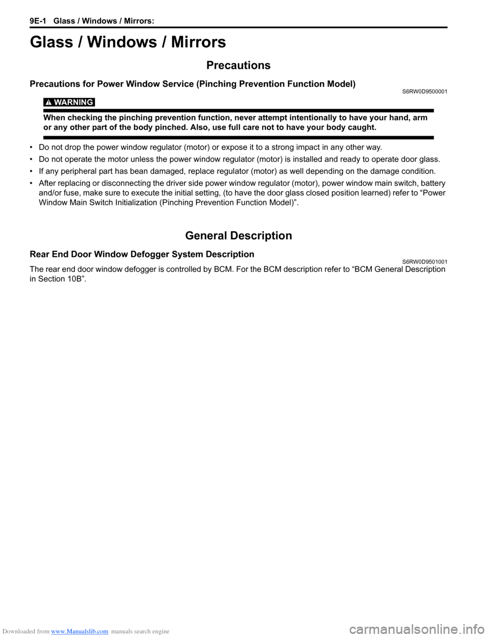
Precautions for Power Window Service (Pinching Prevention Function Model)S6RW0D9500001
WARNING!
When checking the pinching prevention function, never attempt intentionally to have your hand, arm
or any other part of the body pinched. Also, use full care not to have your body caught.
• Do not drop the power window regulator (motor) or expose it to a strong impact in any other way.
• Do not operate the motor unless the power window regulator (motor) is installed and ready to operate door glass.
• If any peripheral part has bean damaged, replace regulator (motor) as well depending on the damage condition.
• After replacing or disconnecting the driver side power window regulator (motor), power window main switch, battery
and/or fuse, make sure to execute the initial setting, (to have the door glass closed position learned) refer to “Power
Window Main Switch Initialization (Pinching Prevention Function Model)”.
General Description
Rear End Door Window Defogger System DescriptionS6RW0D9501001
The rear end door window defogger is controlled by BCM. For the BCM description refer to “BCM General Description
in Section 10B”.
Page 1412 of 1556
Downloaded from www.Manualslib.com manuals search engine 9F-1 Security and Locks:
Body, Cab and Accessories
Security and Locks
General Description
Key Coding ConstructionS6RW0D9601001
Key Usage and Identification
Key is used for ignition and door lock cylinders. Key is cut on both edges to make them reversible.
Key identification is obtained from five character key code stamped on key code tag. Using this key code, key code
cutting combination can be determined from a code list (available to owners of key cutting equipment from suppliers).
Rear End Door Opener System DescriptionS6RW0D9601002
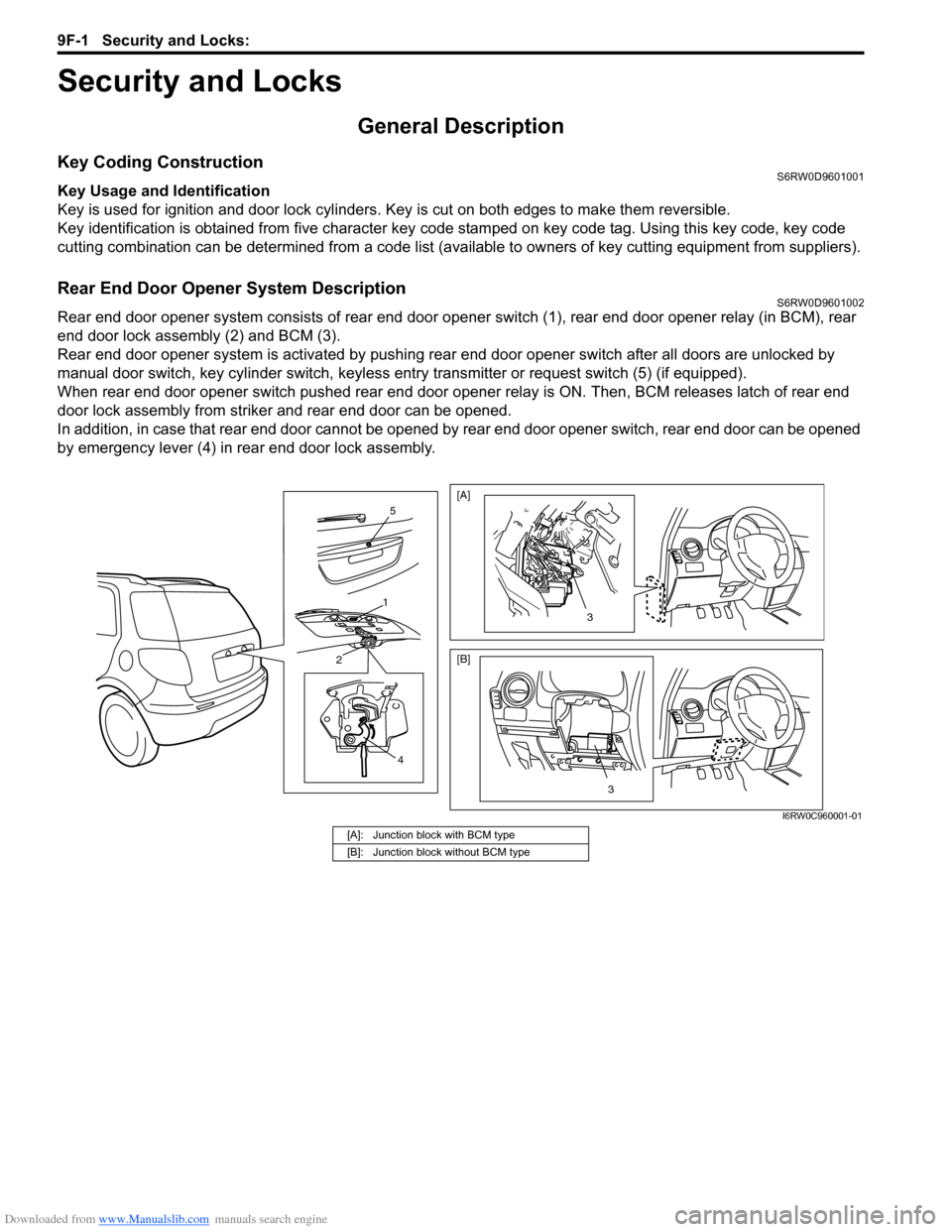
Rear end door opener system consists of rear end door opener switch (1), rear end door opener relay (in BCM), rear
end door lock assembly (2) and BCM (3).
Rear end door opener system is activated by pushing rear end door opener switch after all doors are unlocked by
manual door switch, key cylinder switch, keyless entry transmitter or request switch (5) (if equipped).
When rear end door opener switch pushed rear end door opener relay is ON. Then, BCM releases latch of rear end
door lock assembly from striker and rear end door can be opened.
In addition, in case that rear end door cannot be opened by rear end door opener switch, rear end door can be opened
by emergency lever (4) in rear end door lock assembly.
4
2
1
5
3
[A]
[B]
3
I6RW0C960001-01
[A]: Junction block with BCM type
[B]: Junction block without BCM type
Page 1428 of 1556
Downloaded from www.Manualslib.com manuals search engine 9G-1 Seats:
Body, Cab and Accessories
Seats
Diagnostic Information and Procedures
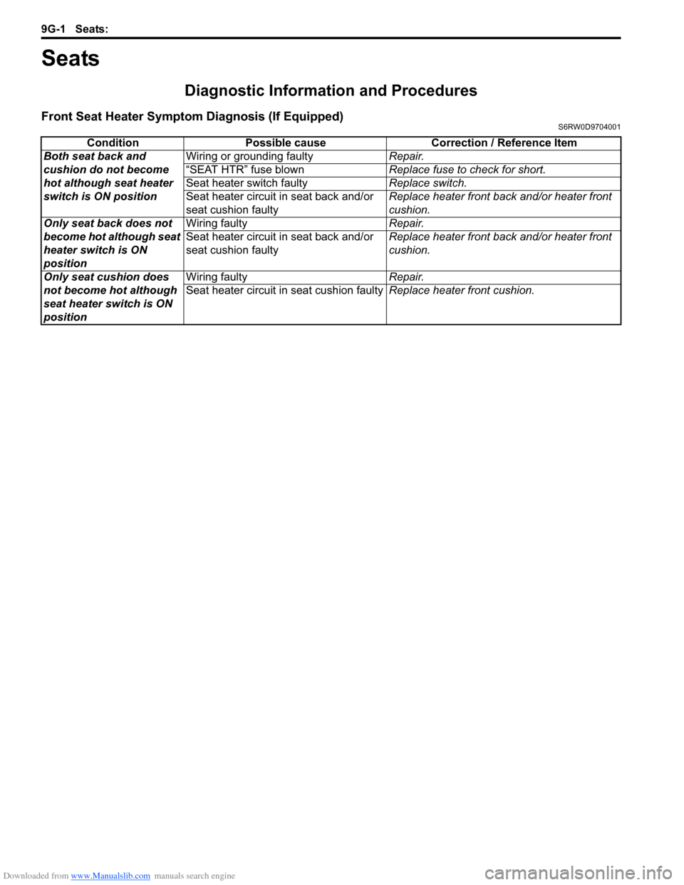
Front Seat Heater Symptom Diagnosis (If Equipped)S6RW0D9704001
Condition Possible cause Correction / Reference Item
Both seat back and
cushion do not become
hot although seat heater
switch is ON positionWiring or grounding faultyRepair.
“SEAT HTR” fuse blownReplace fuse to check for short.
Seat heater switch faultyReplace switch.
Seat heater circuit in seat back and/or
seat cushion faultyReplace heater front back and/or heater front
cushion.
Only seat back does not
become hot although seat
heater switch is ON
positionWiring faultyRepair.
Seat heater circuit in seat back and/or
seat cushion faultyReplace heater front back and/or heater front
cushion.
Only seat cushion does
not become hot although
seat heater switch is ON
positionWiring faultyRepair.
Seat heater circuit in seat cushion faultyReplace heater front cushion.