Page 1493 of 1556

Downloaded from www.Manualslib.com manuals search engine Body Electrical Control System: 10B-20
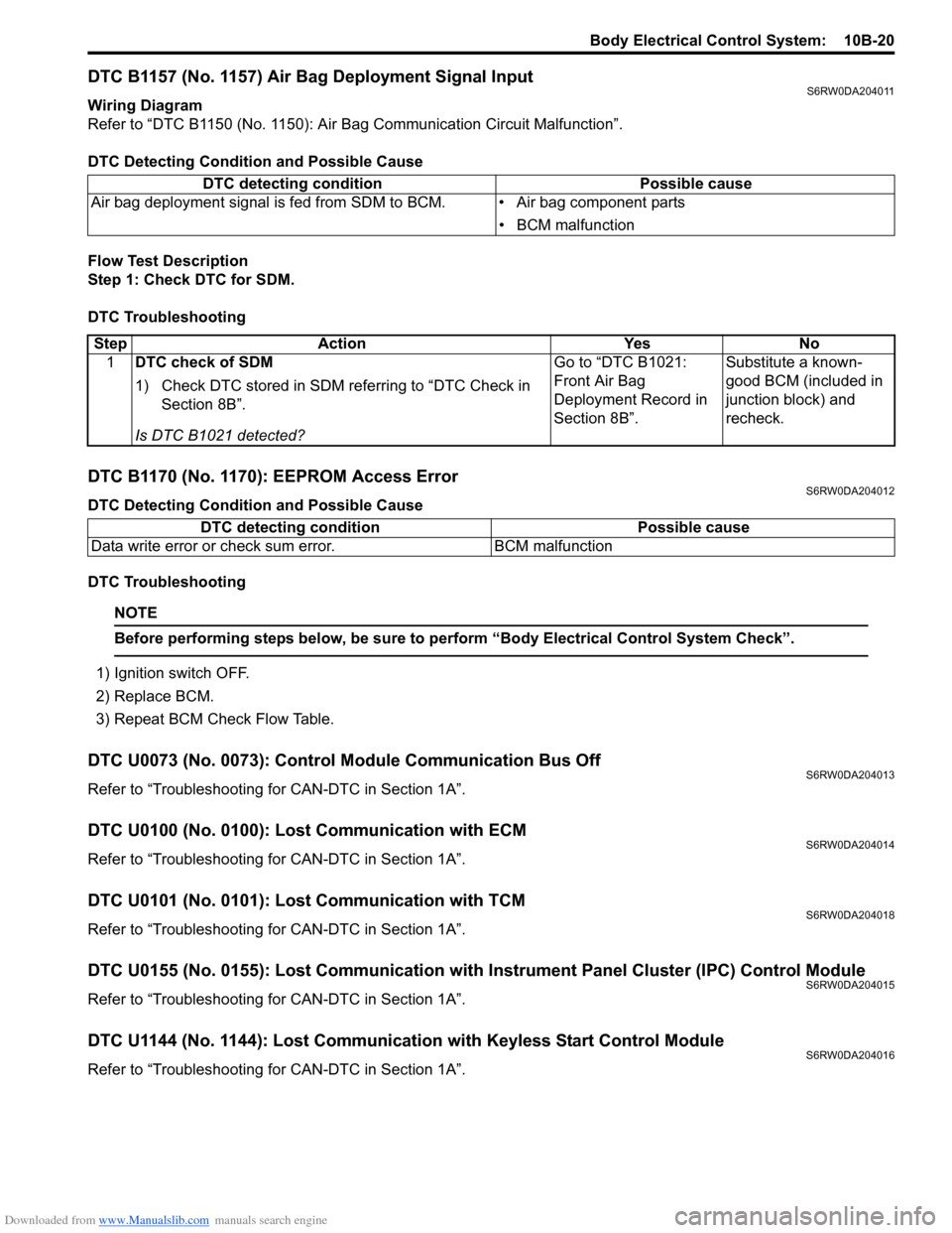
DTC B1157 (No. 1157) Air Bag Deployment Signal InputS6RW0DA204011
Wiring Diagram
Refer to “DTC B1150 (No. 1150): Air Bag Communication Circuit Malfunction”.
DTC Detecting Condition and Possible Cause
Flow Test Description
Step 1: Check DTC for SDM.
DTC Troubleshooting
DTC B1170 (No. 1170): EEPROM Access ErrorS6RW0DA204012
DTC Detecting Condition and Possible Cause
DTC Troubleshooting
NOTE
Before performing steps below, be sure to perform “Body Electrical Control System Check”.
1) Ignition switch OFF.
2) Replace BCM.
3) Repeat BCM Check Flow Table.
DTC U0073 (No. 0073): Control Module Communication Bus OffS6RW0DA204013
Refer to “Troubleshooting for CAN-DTC in Section 1A”.
DTC U0100 (No. 0100): Lost Communication with ECMS6RW0DA204014
Refer to “Troubleshooting for CAN-DTC in Section 1A”.
DTC U0101 (No. 0101): Lost Communication with TCMS6RW0DA204018
Refer to “Troubleshooting for CAN-DTC in Section 1A”.
DTC U0155 (No. 0155): Lost Communication with Instrument Panel Cluster (IPC) Control ModuleS6RW0DA204015
Refer to “Troubleshooting for CAN-DTC in Section 1A”.
DTC U1144 (No. 1144): Lost Communication with Keyless Start Control ModuleS6RW0DA204016
Refer to “Troubleshooting for CAN-DTC in Section 1A”. DTC detecting condition Possible cause
Air bag deployment signal is fed from SDM to BCM. • Air bag component parts
• BCM malfunction
Step Action Yes No
1DTC check of SDM
1) Check DTC stored in SDM referring to “DTC Check in
Section 8B”.
Is DTC B1021 detected?Go to “DTC B1021:
Front Air Bag
Deployment Record in
Section 8B”.Substitute a known-
good BCM (included in
junction block) and
recheck.
DTC detecting condition Possible cause
Data write error or check sum error. BCM malfunction
Page 1511 of 1556

Downloaded from www.Manualslib.com manuals search engine Immobilizer Control System: 10C-9
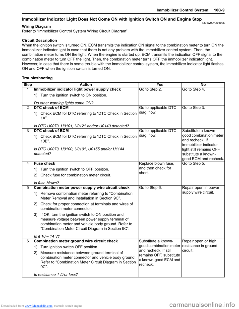
Immobilizer Indicator Light Does Not Come ON with Ignition Switch ON and Engine StopS6RW0DA304006
Wiring Diagram
Refer to “Immobilizer Control System Wiring Circuit Diagram”.
Circuit Description
When the ignition switch is turned ON, ECM transmits the indication ON signal to the combination meter to turn ON the
immobilizer indicator light in case that there is not any problem with the immobilizer control system. Then, the
combination meter turns ON the light. When the engine is started up, ECM transmits the indication OFF signal to the
combination meter to turn OFF the light. Then, the combination meter turns OFF the immobilizer indicator light.
However, in case that there is some trouble with the immobilizer control system, the immobilizer indicator light flashes
ON and OFF when the ignition switch is turned ON.
Troubleshooting
Step Action Yes No
1Immobilizer indicator light power supply check
1) Turn the ignition switch to ON position.
Do other warning lights come ON?Go to Step 2. Go to Step 4.
2DTC check of ECM
1) Check ECM for DTC referring to “DTC Check in Section
1A”.
Is DTC U0073, U0101, U0121 and/or U0140 detected?Go to applicable DTC
diag. flow.Go to Step 3.
3DTC check of BCM
1) Check BCM for DTC referring to “DTC Check in Section
10B”.
Is DTC U0073, U0100, U0101, U0155 and/or U1144
detected?Go to applicable DTC
diag. flow.Substitute a known-
good combination meter
and recheck. If
immobilizer indicator
light still remains OFF,
substitute a known-
good ECM and recheck.
4Fuse check
1) Turn the ignition switch to OFF position.
2) Check fuse for combination meter circuit.
Is fuse blown?Replace blown fuse,
and then check for
short.Go to Step 5.
5Combination meter power supply wire circuit check
1) Remove combination meter referring to “Combination
Meter Removal and Installation in Section 9C”.
2) Check for proper connection at terminals and wires of
combination meter connector.
3) If OK, turn the ignition switch to ON position and
measure voltage between power supply terminal of
combination meter and vehicle body ground. Refer to
“Combination Meter Circuit Diagram in Section 9C”.
Is it 10 – 14 V?Go to Step 6. Repair open in power
supply wire circuit.
6Combination meter ground wire circuit check
1) Turn ignition switch OFF position.
2) Measure resistance between ground terminal of
combination meter connector and vehicle body ground.
Refer to “Combination Meter Circuit Diagram in Section
9C”.
Is resistance 1
Ω or less?Substitute a known-
good combination meter
and recheck. If still
remains OFF, substitute
a known-good ECM and
recheck.Repair open or high
resistance in ground
circuit.
Page 1517 of 1556

Downloaded from www.Manualslib.com manuals search engine Immobilizer Control System: 10C-15
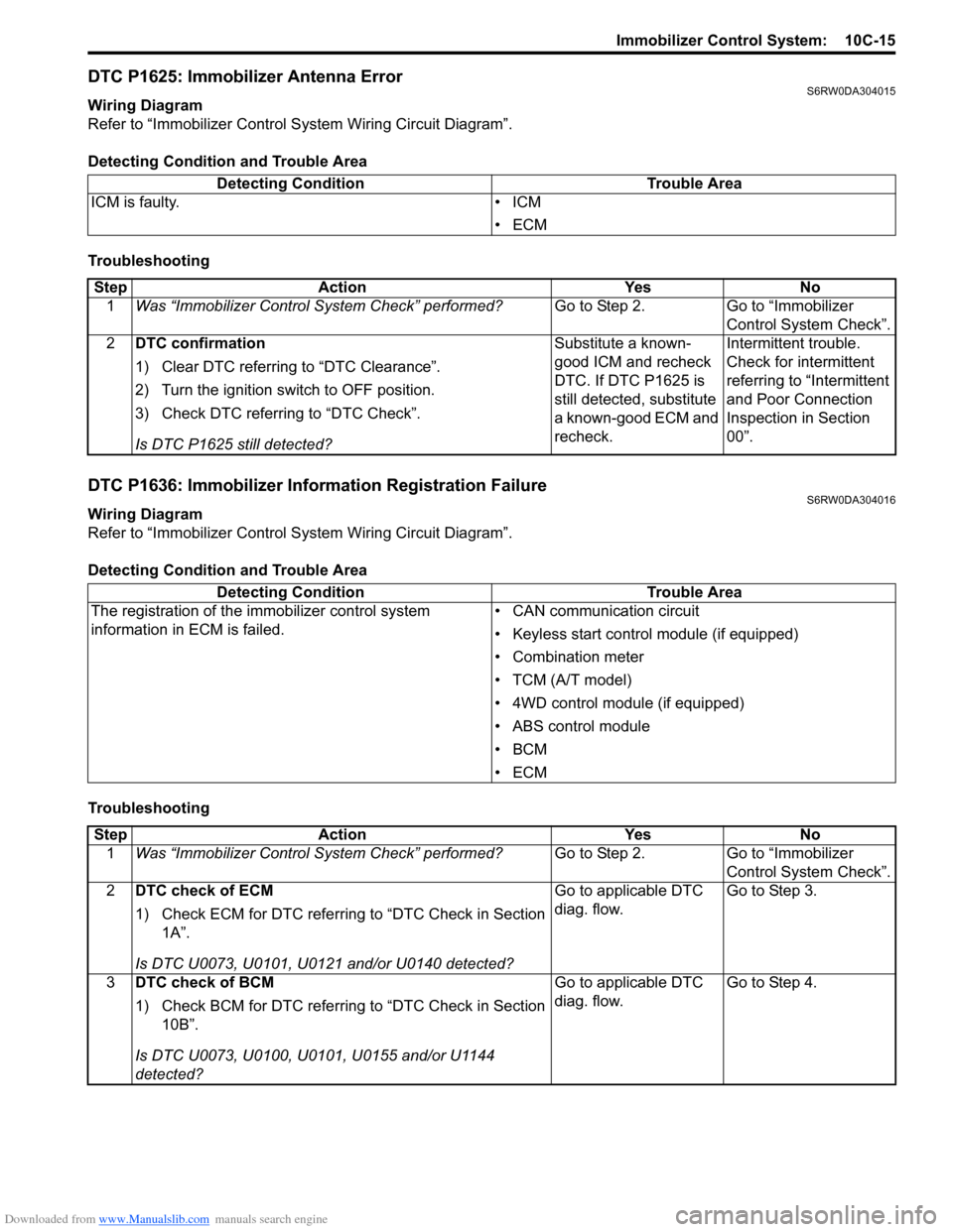
DTC P1625: Immobilizer Antenna ErrorS6RW0DA304015
Wiring Diagram
Refer to “Immobilizer Control System Wiring Circuit Diagram”.
Detecting Condition and Trouble Area
Troubleshooting
DTC P1636: Immobilizer Information Registration FailureS6RW0DA304016
Wiring Diagram
Refer to “Immobilizer Control System Wiring Circuit Diagram”.
Detecting Condition and Trouble Area
TroubleshootingDetecting Condition Trouble Area
ICM is faulty. • ICM
•ECM
Step Action Yes No
1Was “Immobilizer Control System Check” performed?Go to Step 2. Go to “Immobilizer
Control System Check”.
2DTC confirmation
1) Clear DTC referring to “DTC Clearance”.
2) Turn the ignition switch to OFF position.
3) Check DTC referring to “DTC Check”.
Is DTC P1625 still detected?Substitute a known-
good ICM and recheck
DTC. If DTC P1625 is
still detected, substitute
a known-good ECM and
recheck.Intermittent trouble.
Check for intermittent
referring to “Intermittent
and Poor Connection
Inspection in Section
00”.
Detecting Condition Trouble Area
The registration of the immobilizer control system
information in ECM is failed.• CAN communication circuit
• Keyless start control module (if equipped)
• Combination meter
• TCM (A/T model)
• 4WD control module (if equipped)
• ABS control module
•BCM
•ECM
Step Action Yes No
1Was “Immobilizer Control System Check” performed?Go to Step 2. Go to “Immobilizer
Control System Check”.
2DTC check of ECM
1) Check ECM for DTC referring to “DTC Check in Section
1A”.
Is DTC U0073, U0101, U0121 and/or U0140 detected?Go to applicable DTC
diag. flow.Go to Step 3.
3DTC check of BCM
1) Check BCM for DTC referring to “DTC Check in Section
10B”.
Is DTC U0073, U0100, U0101, U0155 and/or U1144
detected?Go to applicable DTC
diag. flow.Go to Step 4.
Page 1519 of 1556

Downloaded from www.Manualslib.com manuals search engine Immobilizer Control System: 10C-17
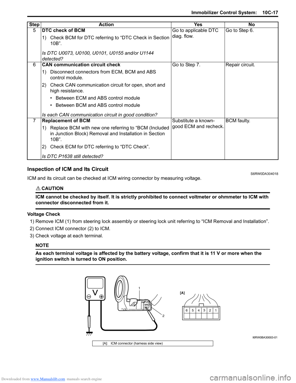
Inspection of ICM and Its CircuitS6RW0DA304018
ICM and its circuit can be checked at ICM wiring connector by measuring voltage.
CAUTION!
ICM cannot be checked by itself. It is strictly prohibited to connect voltmeter or ohmmeter to ICM with
connector disconnected from it.
Voltage Check
1) Remove ICM (1) from steering lock assembly or steering lock unit referring to “ICM Removal and Installation”.
2) Connect ICM connector (2) to ICM.
3) Check voltage at each terminal.
NOTE
As each terminal voltage is affected by the battery voltage, confirm that it is 11 V or more when the
ignition switch is turned to ON position.
5DTC check of BCM
1) Check BCM for DTC referring to “DTC Check in Section
10B”.
Is DTC U0073, U0100, U0101, U0155 and/or U1144
detected?Go to applicable DTC
diag. flow.Go to Step 6.
6CAN communication circuit check
1) Disconnect connectors from ECM, BCM and ABS
control module.
2) Check CAN communication circuit for open, short and
high resistance.
• Between ECM and ABS control module
• Between BCM and ABS control module
Is each CAN communication circuit in good condition?Go to Step 7. Repair circuit.
7Replacement of BCM
1) Replace BCM with new one referring to “BCM (Included
in Junction Block) Removal and Installation in Section
10B”.
2) Check ECM for DTC referring to “DTC Check”.
Is DTC P1638 still detected?Substitute a known-
good ECM and recheck.BCM faulty. Step Action Yes No
1 2 3
4
1
25
6 [A]
I6RW0BA30003-01
[A]: ICM connector (harness side view)