2006 SUZUKI SX4 wheel
[x] Cancel search: wheelPage 644 of 1556

Downloaded from www.Manualslib.com manuals search engine 4E-39 ABS:
Specifications
Tightening Torque SpecificationsS6RW0D4507001
NOTE
The specified tightening torque is also described in the following.
“ABS Hydraulic Unit / Control Module Assembly Components”
Reference:
For the tightening torque of fastener not specified in this section, refer to “Fasteners Information in Section 0A”.
Special Tools and Equipment
Special ToolS6RW0D4508001
Fastening partTightening torque
Note
N⋅mkgf-mlb-ft
Brake pipe flare nut 16 1.6 11.5�)
ABS hydraulic unit / control module assembly
bolt90.9 6.5�)
ABS hydraulic unit / control module assembly
bracket bolt26 2.6 19.0�)
Front wheel speed sensor bolt 11 1.1 8.0�)
Front wheel speed sensor harness clamp bolt 11 1.1 8.0�)
Rear wheel speed sensor bolt 11 1.1 8.0�)
G sensor bolt 3.0 0.3 2.2�)
09950–78220 SUZUKI scan tool
Flare nut wrench (10 mm) —
�)This kit includes following
items. 1. Tech 2, 2. PCMCIA
card, 3. DLC cable, 4. SAE
16/19 adapter, 5. Cigarette
cable, 6. DLC loop back
adapter, 7. Battery power
cable, 8. RS232 cable, 9.
RS232 adapter, 10. RS232
loop back connector, 11.
Storage case, 12. �) / �)
Page 647 of 1556

Downloaded from www.Manualslib.com manuals search engine Table of Contents 5-iii
Diagnostic Information and Procedures ............ 5B-5
Manual Transaxle Symptom Diagnosis............... 5B-5
Repair Instructions .............................................. 5B-5
Manual Transaxle Oil Level Check ..................... 5B-5
Manual Transaxle Oil Change ............................ 5B-6
Differential Side Oil Seal Replacement ............... 5B-7
Gear Shift Control Lever and Cable
Components...................................................... 5B-8
Gear Shift Control Lever and Cable Removal
and Installation .................................................. 5B-9
Gear Select Control Cable Adjustment ............... 5B-9
Back Up Light Switch Removal and
Installation ....................................................... 5B-10
Back Up Light Switch Inspection ....................... 5B-10
Manual Transaxle Unit Components ................. 5B-11
Manual Transaxle Unit Dismounting and
Remounting..................................................... 5B-12
Gear Shift and Select Shaft Assembly
Components.................................................... 5B-13
Gear Shift and Select Shaft Assembly
Removal and Installation................................. 5B-14
Gear Shift and Select Shaft Assembly
Disassembly and Reassembly ........................ 5B-15
Manual Transaxle Assembly Components........ 5B-16
Fifth Gear Disassembly and Reassembly ......... 5B-17
Manual Transaxle Assembly Disassembly
and Reassembly ............................................. 5B-19
Right Case Disassembly and Reassembly ....... 5B-24
Left Case Disassembly and Reassembly.......... 5B-25
Input Shaft and Countershaft Components....... 5B-27
Input Shaft Disassembly and Reassembly........ 5B-28
Countershaft Disassembly and Reassembly .... 5B-31
Gear Shift Shaft Components ........................... 5B-35
5th and Reverse Gear Shift Shafts
Disassembly and Reassembly ........................ 5B-35
Gear Shift Shaft and Fork Inspection ................ 5B-35
Differential Components ................................... 5B-36Differential Disassembly and Reassembly ........ 5B-36
Specifications .....................................................5B-38
Tightening Torque Specifications ...................... 5B-38
Special Tools and Equipment ...........................5B-39
Recommended Service Material ....................... 5B-39
Special Tool ...................................................... 5B-39
Clutch ....................................................... 5C-1
General Description .............................................5C-1
Clutch (Hydraulic Type) Construction .................5C-1
Diagnostic Information and Procedures ............5C-2
Clutch System Symptom Diagnosis ....................5C-2
Repair Instructions ..............................................5C-3
Clutch Pedal Inspection ......................................5C-3
Clutch Fluid Level Inspection ..............................5C-3
Air Bleeding of Clutch System.............................5C-3
Clutch Fluid Pipe and Hose Location ..................5C-4
Clutch Fluid Pipe Removal and Installation.........5C-4
Clutch Fluid Pipe Inspection................................5C-4
Clutch Master Cylinder Removal and
Installation .........................................................5C-5
Clutch Operating Cylinder Assembly
Removal and Installation ...................................5C-5
Clutch Operating Cylinder Assembly
Inspection ..........................................................5C-6
Clutch Cover, Clutch Disc and Flywheel
Components ......................................................5C-6
Clutch Cover, Clutch Disc and Flywheel
Removal and Installation ...................................5C-7
Clutch Cover, Clutch Disc and Flywheel
Inspection ..........................................................5C-8
Specifications .......................................................5C-9
Tightening Torque Specifications ........................5C-9
Special Tools and Equipment ...........................5C-10
Recommended Service Material .......................5C-10
Special Tool ......................................................5C-10
Page 666 of 1556

Downloaded from www.Manualslib.com manuals search engine 5A-18 Automatic Transmission/Transaxle:
Step 2. DTC / Freeze Frame Data Check, Record and
Clearance
First, referring to “DTC Check”, check DTC and pending
DTC. If DTC exists, print or write down DTC and freeze
frame data and then clear malfunction DTC(s) by
referring to “DTC Clearance”. Malfunction DTC indicates
malfunction in the system but it is not possible to know
from it whether the malfunction is occurring now or it
occurred in the past and normal condition has been
restored. In order to know that, check symptom in
question according to Step 5 and then recheck DTC
according to Step 6.
Diagnosing a trouble based on the DTC in this step only
or failure to clear the DTC in this step may result in an
faulty diagnosis, trouble diagnosis of a normal circuit or
difficulty in troubleshooting which is otherwise
unnecessary.
Step 3 and 4. Visual Inspection
As a preliminary step, be sure to perform visual check of
the items that support proper function of the engine and
automatic transaxle referring to “Visual Inspection”.
Step 5. Trouble Symptom Confirmation
Check trouble symptoms based on information obtained
in “Step 1. Customer Complaint Analysis: ” and “Step 2.
DTC / Freeze Frame Data Check, Record and
Clearance: ”.
Also, reconfirm DTC according to “DTC Confirmation
Procedure” described in each DTC flow.
Step 6 and 7. Rechecking and Record of DTC and
Freeze Frame Data
Refer to “DTC Check” for checking procedure.Step 8. A/T Basic Check and A/T Symptom
Diagnosis
Perform basic check of A/T according to “A/T Basic
Check” first. When the end of the flow has been reached,
check the parts of the system suspected as a possible
cause referring to “A/T Symptom Diagnosis” and based
on symptoms appearing on the vehicle (symptoms
obtained through steps of customer complaint analysis,
trouble symptom confirmation and/or A/T basic check)
and repair or replace faulty parts, if any.
Step 9. Troubleshooting for DTC
Based on the DTC indicated in Step 6 / 7 and referring to
“applicable DTC flow”, locate the cause of the trouble,
namely in a sensor, switch, wire harness, connector,
actuator, TCM or other part and repair or replace faulty
parts.
Step 10. Check for Intermittent Problem
Check parts where an intermittent trouble is easy to
occur (e.g. wire harness, connector, etc.), referring to
“Intermittent and Poor Connection Inspection in Section
00” and related circuit of DTC recorded in Step 2.
Step 11. Final Confirmation Test
Confirm that the problem symptom has gone and the
vehicle is free from any abnormal conditions. If what has
been repaired is related to the malfunction DTC, clear
the DTC once and check to ensure that no malfunction
DTC is indicated.
Visual InspectionS6RW0D5104002
Visually check the following parts and systems.
Inspection item Referring
• A/T fluid ----- level, leakage, color “Automatic Transaxle Fluid Level Inspection in
Section 0B”
• A/T fluid hoses ----- disconnection, looseness, deterioration “A/T Fluid Cooler Hoses Replacement”
• Throttle cable (if equipped) ----- play (under warm engine),
installation
• A/T select cable ----- installation “Select Cable Removal and Installation”
• Engine oil ----- level, leakage “Engine Oil and Filter Change in Section 0B”
• Engine coolant ----- level, leakage “Engine Coolant Change in Section 0B”
• Engine mountings ----- play, looseness, damage “Engine Assembly Removal and Installation in
Section 1D”
• Suspension ----- play, looseness “Suspension, Wheels and Tires Symptom
Diagnosis in Section 2A”
• Drive shafts ----- damage “Front Drive Shaft Assembly On-Vehicle Inspection
in Section 3A”
• Battery ----- indicator condition, corrosion of terminal “Battery Inspection in Section 1J”
• Connectors of electric wire harness ----- disconnection, friction “Electronic Shift Control System Components
Location”
• Fuses ----- burning
• Parts ----- installation, damage
• Bolts ----- looseness
• Other parts that can be checked visually
Page 679 of 1556

Downloaded from www.Manualslib.com manuals search engine Automatic Transmission/Transaxle: 5A-31
Stall TestS6RW0D5104013
This test is to check overall performance of automatic transaxle and engine by measuring stall speed at “D” and “R”
ranges. Be sure to perform this test only when transaxle fluid is at normal operating temperature and its level is
between FULL and LOW marks.
CAUTION!
• Do not run engine at stall more than 5 seconds continuously, or fluid temperature may rise
excessively high.
• After performing stall test, be sure to leave engine running at idle for longer than 1 minute before
another stall test.
1) Apply parking brake and block wheels.
2) Install tachometer.
3) Start engine with select lever shifted to “P” range.
4) Depress brake pedal fully.
5) Shift select lever to “D” range and depress accelerator pedal fully while watching tachometer. Read engine rpm
quickly when it has become constant (stall speed).
6) Release accelerator pedal immediately after stall speed is checked.
7) In the same way, check stall speed in “R” range.
8) Stall speed should be within the following specification.
Engine stall speed
Standard: 2,200 – 2,600 rpm
Troubleshooting
Condition Possible cause Correction / Reference Item
Lower than standard level
in both “D” and “R” rangeEngine output torque failureInspect and repair engine.
Faulty one-way clutch of torque
converterReplace torque converter.
Higher than standard
level in “D” rangeMalfunction of pressure control solenoid
valve (Low line pressure)Inspect. If NG, replace valve body assembly.
Faulty valve body componentReplace valve body assembly.
Slippery forward clutchInspect. If NG, replace.
Faulty one-way No.2 clutchInspect. If NG, replace.
Leakage from “D” range fluid pressure
circuitOverhaul or replace valve body assembly.
Higher than standard
level in “R” rangeMalfunction of pressure control solenoid
valve (Low line pressure)Inspect. If NG, replace valve body assembly.
Faulty valve body componentReplace valve body assembly.
Slippery reverse clutchInspect. If NG, replace.
Slippery 1st and reverse brakeInspect. If NG, replace.
Leakage from “R” range fluid pressure
circuitOverhaul or replace valve body assembly.
Higher than standard
level in both “D” and “R”
rangeMalfunction of pressure control solenoid
valve (Low line pressure)Inspect. If NG, replace valve body assembly.
Faulty valve body componentReplace valve body assembly.
Clogged oil strainerReplace.
Faulty oil pumpInspect. If NG, replace.
Leakage from both “D” and “R” range
fluid pressure circuitOverhaul or replace valve body assembly.
Page 680 of 1556

Downloaded from www.Manualslib.com manuals search engine 5A-32 Automatic Transmission/Transaxle:
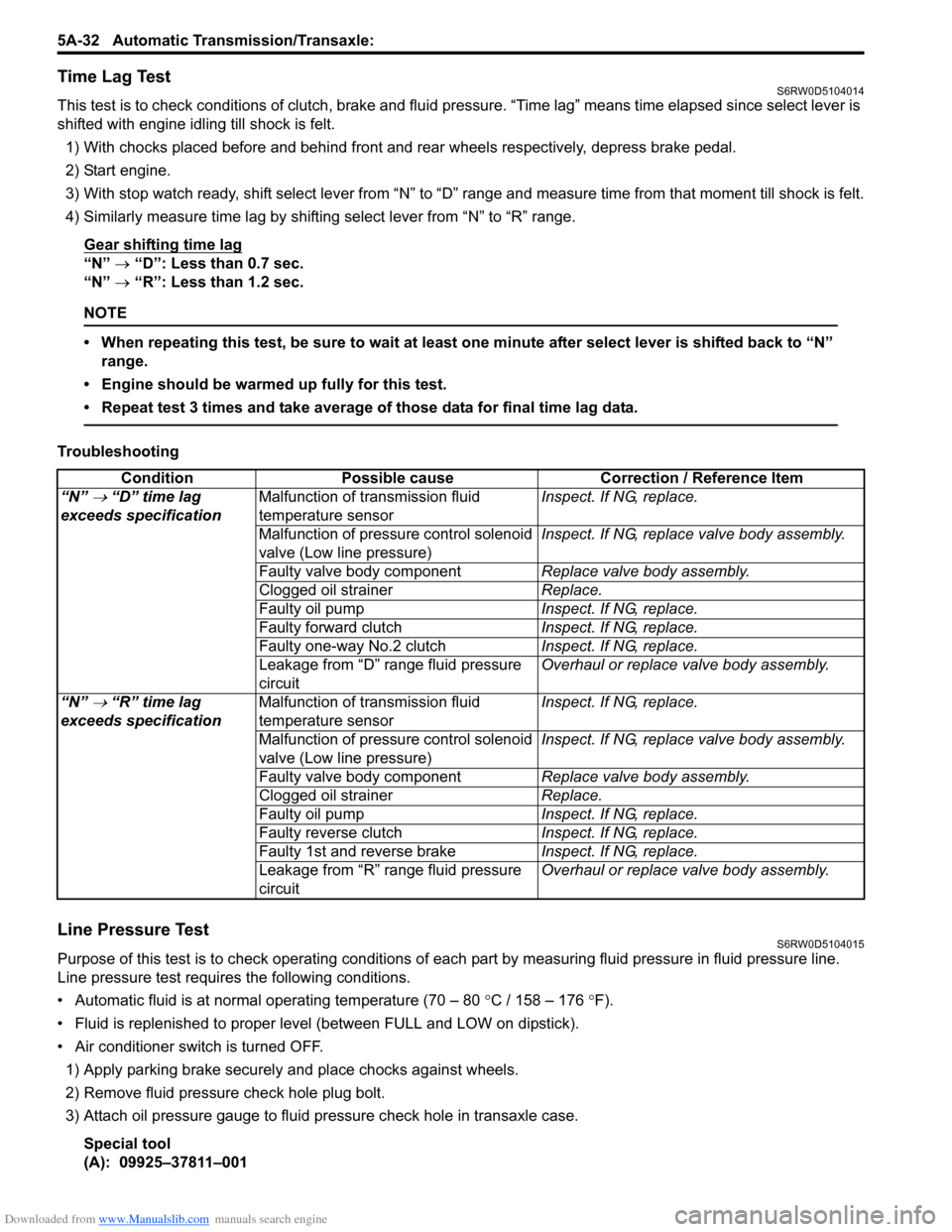
Time Lag TestS6RW0D5104014
This test is to check conditions of clutch, brake and fluid pressure. “Time lag” means time elapsed since select lever is
shifted with engine idling till shock is felt.
1) With chocks placed before and behind front and rear wheels respectively, depress brake pedal.
2) Start engine.
3) With stop watch ready, shift select lever from “N” to “D” range and measure time from that moment till shock is felt.
4) Similarly measure time lag by shifting select lever from “N” to “R” range.
Gear shifting time lag
“N” → “D”: Less than 0.7 sec.
“N” → “R”: Less than 1.2 sec.
NOTE
• When repeating this test, be sure to wait at least one minute after select lever is shifted back to “N”
range.
• Engine should be warmed up fully for this test.
• Repeat test 3 times and take average of those data for final time lag data.
Troubleshooting
Line Pressure TestS6RW0D5104015
Purpose of this test is to check operating conditions of each part by measuring fluid pressure in fluid pressure line.
Line pressure test requires the following conditions.
• Automatic fluid is at normal operating temperature (70 – 80 °C / 158 – 176 °F).
• Fluid is replenished to proper level (between FULL and LOW on dipstick).
• Air conditioner switch is turned OFF.
1) Apply parking brake securely and place chocks against wheels.
2) Remove fluid pressure check hole plug bolt.
3) Attach oil pressure gauge to fluid pressure check hole in transaxle case.
Special tool
(A): 09925–37811–001Condition Possible cause Correction / Reference Item
“N”
→ “D” time lag
exceeds specificationMalfunction of transmission fluid
temperature sensorInspect. If NG, replace.
Malfunction of pressure control solenoid
valve (Low line pressure)Inspect. If NG, replace valve body assembly.
Faulty valve body componentReplace valve body assembly.
Clogged oil strainerReplace.
Faulty oil pumpInspect. If NG, replace.
Faulty forward clutchInspect. If NG, replace.
Faulty one-way No.2 clutchInspect. If NG, replace.
Leakage from “D” range fluid pressure
circuitOverhaul or replace valve body assembly.
“N”
→ “R” time lag
exceeds specificationMalfunction of transmission fluid
temperature sensorInspect. If NG, replace.
Malfunction of pressure control solenoid
valve (Low line pressure)Inspect. If NG, replace valve body assembly.
Faulty valve body componentReplace valve body assembly.
Clogged oil strainerReplace.
Faulty oil pumpInspect. If NG, replace.
Faulty reverse clutchInspect. If NG, replace.
Faulty 1st and reverse brakeInspect. If NG, replace.
Leakage from “R” range fluid pressure
circuitOverhaul or replace valve body assembly.
Page 730 of 1556

Downloaded from www.Manualslib.com manuals search engine 5A-82 Automatic Transmission/Transaxle:
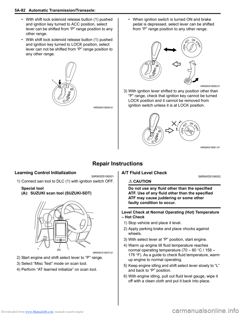
• With shift lock solenoid release button (1) pushed
and ignition key turned to ACC position, select
lever can be shifted from “P” range position to any
other range.
• With shift lock solenoid release button (1) pushed
and ignition key turned to LOCK position, select
lever can not be shifted from “P” range position to
any other range.• When ignition switch is turned ON and brake
pedal is depressed, select lever can be shifted
from “P” range position to any other range.
3) With ignition lever shifted to any position other than
“P” range, check that ignition key cannot be turned
LOCK position and it cannot be removed from
ignition switch unless it is at LOCK position.
Repair Instructions
Learning Control InitializationS6RW0D5106001
1) Connect san tool to DLC (1) with ignition switch OFF.
Special tool
(A): SUZUKI scan tool (SUZUKI-SDT)
2) Start engine and shift select lever to “P” range.
3) Select “Misc Test” mode on scan tool.
4) Perform “AT learned initialize” on scan tool.
A/T Fluid Level CheckS6RW0D5106002
CAUTION!
Do not use any fluid other than the specified
ATF. Use of any fluid other than the specified
ATF may cause juddering or some other
faulty condition to occur.
Level Check at Normal Operating (Hot) Temperature
– Hot Check
1) Stop vehicle and place it level.
2) Apply parking brake and place chocks against
wheels.
3) With select lever at “P” position, start engine.
4) Warm up engine till fluid temperature reaches
normal operating temperature (70 – 80 °C / 158 –
176 °F). As a guide to check fluid temperature, warm
up engine to normal operating.
5) Keep engine idling and shift select lever slowly to “L”
and back to “P” position.
6) With engine idling, pull out fluid level gauge, wipe it
off with a clean cloth and put it back into place.
1
I4RS0A510049-01
I4RS0A510050-01
I4RS0A510051-01
(A) 1I5RW0C510072-01
Page 854 of 1556

Downloaded from www.Manualslib.com manuals search engine 5C-1 Clutch:
Transmission / Transaxle
Clutch
General Description
Clutch (Hydraulic Type) ConstructionS6RW0D5301001
The clutch is a diaphragm spring clutch of a dry single disc type. The diaphragm spring is of a tapering-finger type,
which is a solid ring in the outer diameter part, with a series of tapered fingers pointing inward.
The disc, carrying four torsional coil springs, is positioned on the transaxle input shaft with an involute spline fit.
The clutch cover is secured to the flywheel, and carries the diaphragm spring in such a way that the peripheral edge
part of the spring pushes on the pressure plate against the flywheel (with the disc in between), when the clutch release
bearing (incorporated in clutch operating cylinder) is held back. This is the engaged condition of the clutch.
Depressing the clutch pedal causes the release bearing (incorporated in clutch operating cylinder) to advance and
pushes on the tips of the tapered fingers of the diaphragm spring. When this happens, the diaphragm spring pulls the
pressure plate away from the flywheel, thereby interrupting the flow of drive from flywheel through clutch disc to
transaxle input shaft. Clutch fluid is supplied from brake fluid reservoir. Clutch fluid level can be checked by brake fluid
level of brake fluid reservoir.
I5RW0A530001-01
1. Crankshaft 4. Pressure plate 7. Operating cylinder assembly
2. Flywheel 5. Clutch cover 8. Input shaft bearing
3. Clutch disc 6. Diaphragm spring 9. Input shaft
Page 855 of 1556

Downloaded from www.Manualslib.com manuals search engine Clutch: 5C-2
Diagnostic Information and Procedures
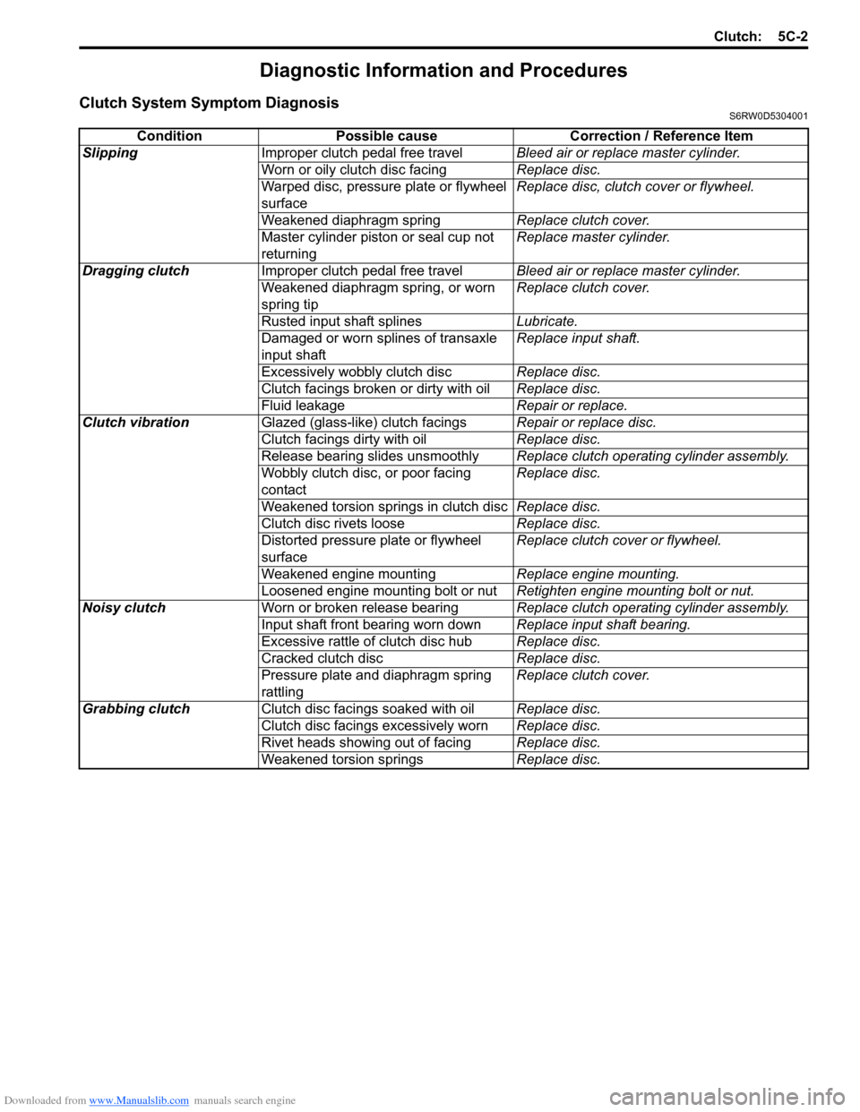
Clutch System Symptom DiagnosisS6RW0D5304001
Condition Possible cause Correction / Reference Item
SlippingImproper clutch pedal free travelBleed air or replace master cylinder.
Worn or oily clutch disc facingReplace disc.
Warped disc, pressure plate or flywheel
surfaceReplace disc, clutch cover or flywheel.
Weakened diaphragm springReplace clutch cover.
Master cylinder piston or seal cup not
returningReplace master cylinder.
Dragging clutchImproper clutch pedal free travelBleed air or replace master cylinder.
Weakened diaphragm spring, or worn
spring tipReplace clutch cover.
Rusted input shaft splinesLubricate.
Damaged or worn splines of transaxle
input shaftReplace input shaft.
Excessively wobbly clutch discReplace disc.
Clutch facings broken or dirty with oilReplace disc.
Fluid leakageRepair or replace.
Clutch vibrationGlazed (glass-like) clutch facingsRepair or replace disc.
Clutch facings dirty with oilReplace disc.
Release bearing slides unsmoothlyReplace clutch operating cylinder assembly.
Wobbly clutch disc, or poor facing
contactReplace disc.
Weakened torsion springs in clutch discReplace disc.
Clutch disc rivets looseReplace disc.
Distorted pressure plate or flywheel
surfaceReplace clutch cover or flywheel.
Weakened engine mountingReplace engine mounting.
Loosened engine mounting bolt or nutRetighten engine mounting bolt or nut.
Noisy clutchWorn or broken release bearingReplace clutch operating cylinder assembly.
Input shaft front bearing worn downReplace input shaft bearing.
Excessive rattle of clutch disc hubReplace disc.
Cracked clutch discReplace disc.
Pressure plate and diaphragm spring
rattlingReplace clutch cover.
Grabbing clutchClutch disc facings soaked with oilReplace disc.
Clutch disc facings excessively wornReplace disc.
Rivet heads showing out of facingReplace disc.
Weakened torsion springsReplace disc.