2006 SUZUKI SX4 Actuator
[x] Cancel search: ActuatorPage 1021 of 1556
Downloaded from www.Manualslib.com manuals search engine Air Conditioning System: Automatic Type 7B-81
HVAC Unit Removal and InstallationS6RW0D7226003
Refer to “HVAC Unit Removal and Installation”.
Temperature Control Actuator Removal and
Installation
S6RW0D7226004
Removal
1) Disconnect negative (–) cable at battery.
2) Remove steering column hole cover from instrument
panel.
3) Remove driver side foot duct from HVAC unit.
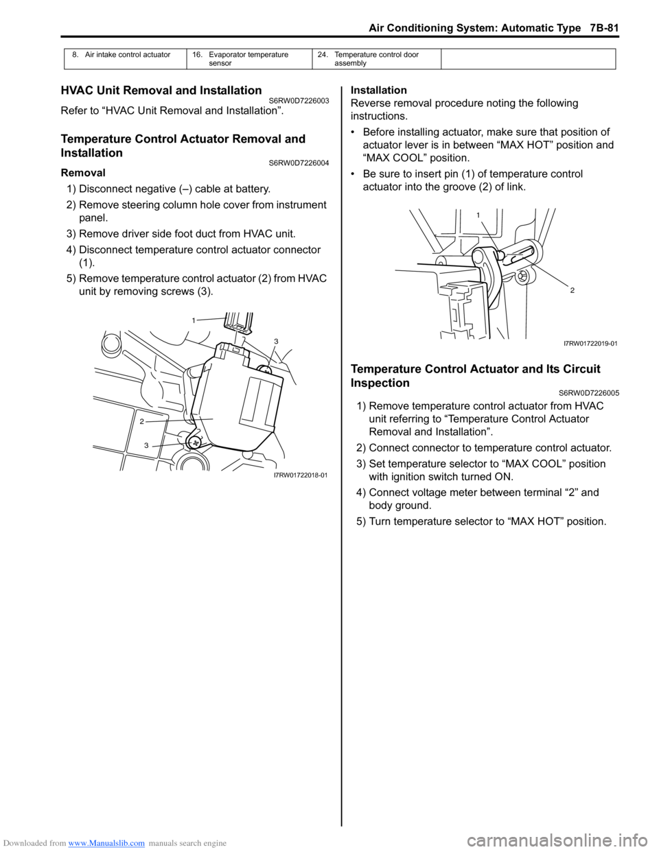
4) Disconnect temperature control actuator connector
(1).
5) Remove temperature control actuator (2) from HVAC
unit by removing screws (3).Installation
Reverse removal procedure noting the following
instructions.
• Before installing actuator, make sure that position of
actuator lever is in between “MAX HOT” position and
“MAX COOL” position.
• Be sure to insert pin (1) of temperature control
actuator into the groove (2) of link.
Temperature Control Actuator and Its Circuit
Inspection
S6RW0D7226005
1) Remove temperature control actuator from HVAC
unit referring to “Temperature Control Actuator
Removal and Installation”.
2) Connect connector to temperature control actuator.
3) Set temperature selector to “MAX COOL” position
with ignition switch turned ON.
4) Connect voltage meter between terminal “2” and
body ground.
5) Turn temperature selector to “MAX HOT” position.
8. Air intake control actuator 16. Evaporator temperature
sensor24. Temperature control door
assembly
3
2
3
1
I7RW01722018-01
1
2
I7RW01722019-01
Page 1022 of 1556
Downloaded from www.Manualslib.com manuals search engine 7B-82 Air Conditioning System: Automatic Type
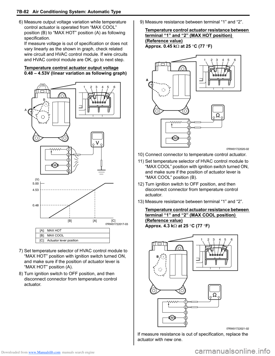
6) Measure output voltage variation while temperature
control actuator is operated from “MAX COOL”
position (B) to “MAX HOT” position (A) as following
specification.
If measure voltage is out of specification or does not
vary linearly as the shown in graph, check related
wire circuit and HVAC control module. If wire circuits
and HVAC control module are OK, go to next step.
Temperature control actuator output voltage
0.48 – 4.53V (linear variation as following graph)
7) Set temperature selector of HVAC control module to
“MAX HOT” position with ignition switch turned ON,
and make sure if the position of actuator lever is
“MAX HOT” position (A).
8) Turn ignition switch to OFF position, and then
disconnect connector from temperature control
actuator.9) Measure resistance between terminal “1” and “2”.
Temperature control actuator resistance between
terminal “1” and “2” (MAX HOT position)
(Reference value)
Approx. 0.45 kΩ at 25 °C (77 °F)
10) Connect connector to temperature control actuator.
11) Set temperature selector of HVAC control module to
“MAX COOL” position with ignition switch turned ON,
and make sure if the position of actuator lever is
“MAX COOL” position (B).
12) Turn ignition switch to OFF position, and then
disconnect connector from temperature control
actuator.
13) Measure resistance between terminal “1” and “2”.
Temperature control actuator resistance between
terminal “1” and “2” (MAX COOL position)
(Reference value)
Approx. 4.3 kΩ at 25 °C (77 °F)
If measure resistance is out of specification, replace the
actuator with new one.[A]: MAX HOT
[B]: MAX COOL
[C]: Actuator lever position
123456
6
M5
3
2
1
AB
4.53
0.48 5.00(V)
[C]
[A] [B]
I7RW01722017-03
123456
6
M5
3
2
1
A
I7RW01722020-02
123456
6
M5
3
2
1
B
I7RW01722021-02
Page 1023 of 1556
Downloaded from www.Manualslib.com manuals search engine Air Conditioning System: Automatic Type 7B-83
Air Flow Control Actuator Removal and
Installation
S6RW0D7226006
Removal
1) Disconnect negative cable at battery.
2) Remove steering column hole cover from instrument
panel.
3) Remove driver side foot duct from HVAC unit.
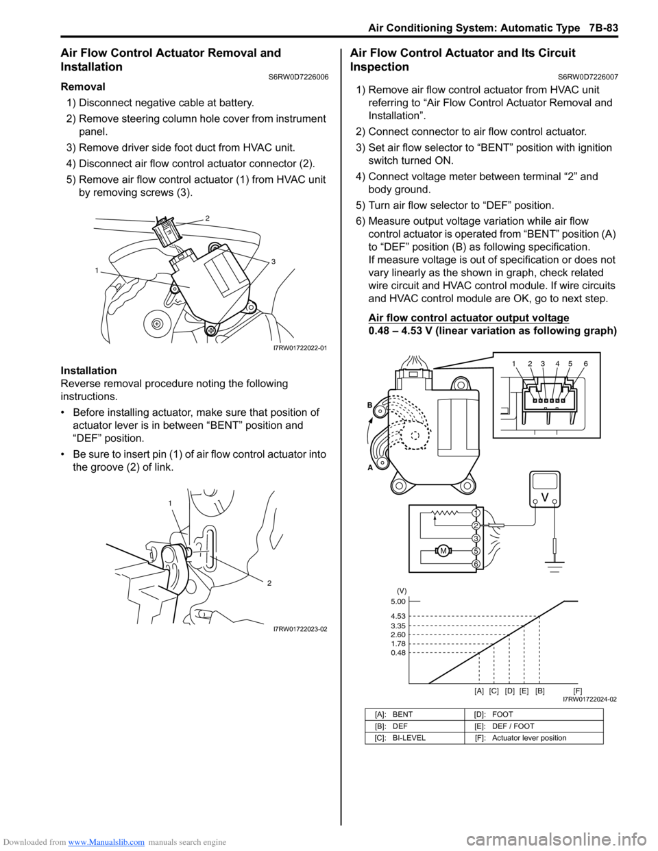
4) Disconnect air flow control actuator connector (2).
5) Remove air flow control actuator (1) from HVAC unit
by removing screws (3).
Installation
Reverse removal procedure noting the following
instructions.
• Before installing actuator, make sure that position of
actuator lever is in between “BENT” position and
“DEF” position.
• Be sure to insert pin (1) of air flow control actuator into
the groove (2) of link.
Air Flow Control Actuator and Its Circuit
Inspection
S6RW0D7226007
1) Remove air flow control actuator from HVAC unit
referring to “Air Flow Control Actuator Removal and
Installation”.
2) Connect connector to air flow control actuator.
3) Set air flow selector to “BENT” position with ignition
switch turned ON.
4) Connect voltage meter between terminal “2” and
body ground.
5) Turn air flow selector to “DEF” position.
6) Measure output voltage variation while air flow
control actuator is operated from “BENT” position (A)
to “DEF” position (B) as following specification.
If measure voltage is out of specification or does not
vary linearly as the shown in graph, check related
wire circuit and HVAC control module. If wire circuits
and HVAC control module are OK, go to next step.
Air flow control actuator output voltage
0.48 – 4.53 V (linear variation as following graph)
13
2
I7RW01722022-01
1
2
I7RW01722023-02
[A]: BENT [D]: FOOT
[B]: DEF [E]: DEF / FOOT
[C]: BI-LEVEL [F]: Actuator lever position
123456
6
M5
3
2
1 A
B
(V)
4.53
3.35
2.60
1.78
0.48
[A][B]
[C] [D] [E][F]5.00
I7RW01722024-02
Page 1024 of 1556
Downloaded from www.Manualslib.com manuals search engine 7B-84 Air Conditioning System: Automatic Type
7) Set air flow selector of HVAC control module to
“DEF” position with ignition switch turned ON, and
make sure if the position of actuator lever is “DEF”
position (A).
8) Turn ignition switch to OFF position, and then
disconnect connector from air flow control actuator.
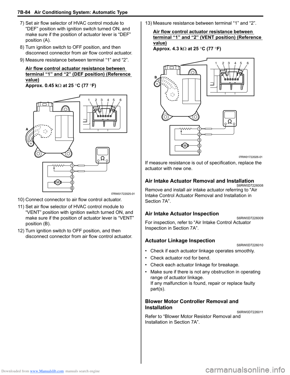
9) Measure resistance between terminal “1” and “2”.
Air flow control actuator resistance between
terminal “1” and “2” (DEF position) (Reference
value)
Approx. 0.45 kΩ at 25 °C (77 °F)
10) Connect connector to air flow control actuator.
11) Set air flow selector of HVAC control module to
“VENT” position with ignition switch turned ON, and
make sure if the position of actuator lever is “VENT”
position (B).
12) Turn ignition switch to OFF position, and then
disconnect connector from air flow control actuator.13) Measure resistance between terminal “1” and “2”.
Air flow control actuator resistance between
terminal “1” and “2” (VENT position) (Reference
value)
Approx. 4.3 kΩ at 25 °C (77 °F)
If measure resistance is out of specification, replace the
actuator with new one.
Air Intake Actuator Removal and InstallationS6RW0D7226008
Remove and install air intake actuator referring to “Air
Intake Control Actuator Removal and Installation in
Section 7A”.
Air Intake Actuator InspectionS6RW0D7226009
For inspection, refer to “Air Intake Control Actuator
Inspection in Section 7A”.
Actuator Linkage InspectionS6RW0D7226010
• Check if each actuator linkage operates smoothly.
• Check actuator rod for bend.
• Check each actuator linkage for breakage.
• Make sure if there is not any obstruction in operating
range of actuator linkage.
If any malfunction is found, repair or replace faulty
part(s).
Blower Motor Controller Removal and
Installation
S6RW0D7226011
Refer to “Blower Motor Resistor Removal and
Installation in Section 7A”.
123456
6
M5
3
2
1 A
I7RW01722025-01
123456
6
M5
3
2
1 B
I7RW01722026-01
Page 1163 of 1556
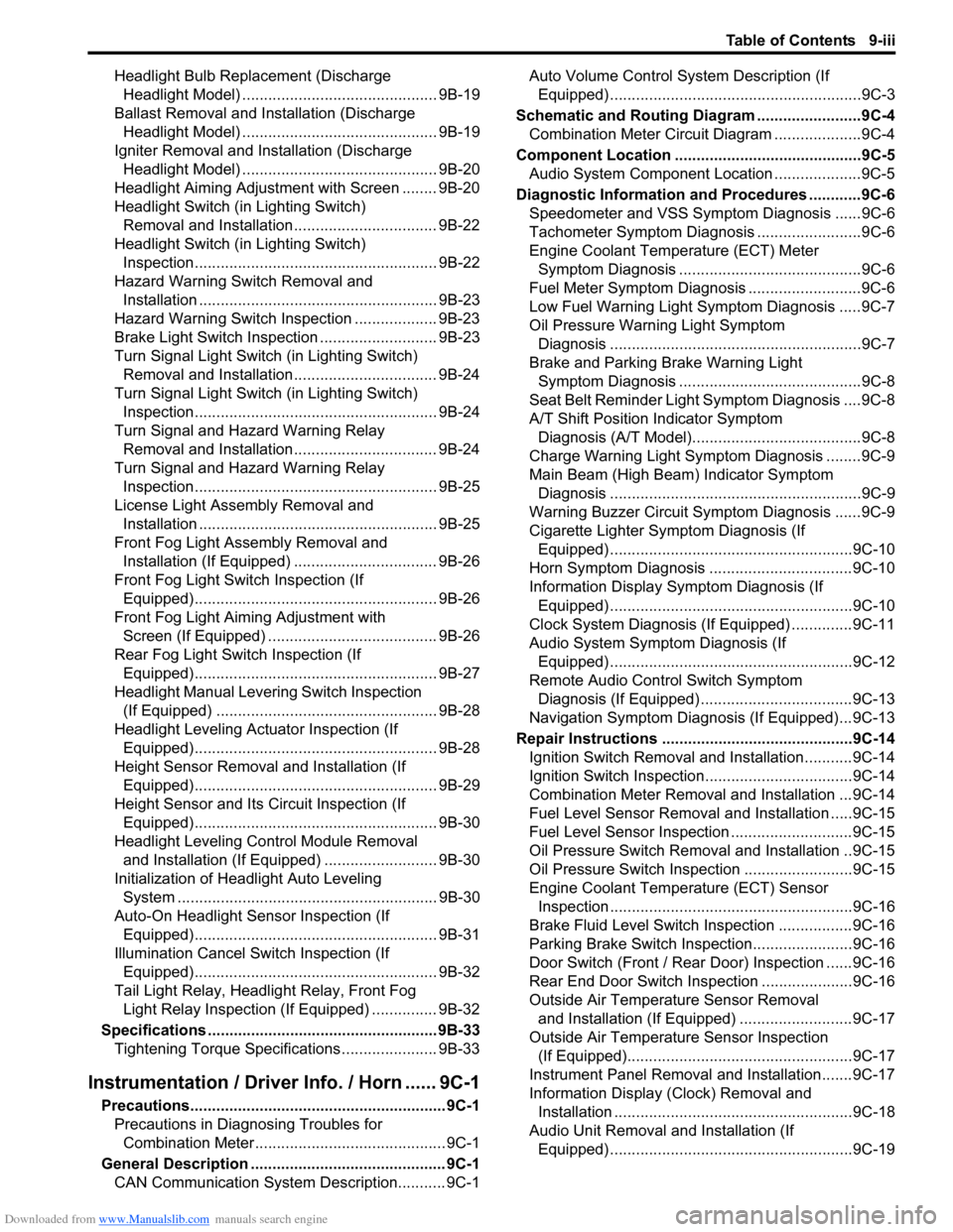
Downloaded from www.Manualslib.com manuals search engine Table of Contents 9-iii
Headlight Bulb Replacement (Discharge
Headlight Model) ............................................. 9B-19
Ballast Removal and Installation (Discharge
Headlight Model) ............................................. 9B-19
Igniter Removal and Installation (Discharge
Headlight Model) ............................................. 9B-20
Headlight Aiming Adjustment with Screen ........ 9B-20
Headlight Switch (in Lighting Switch)
Removal and Installation................................. 9B-22
Headlight Switch (in Lighting Switch)
Inspection........................................................ 9B-22
Hazard Warning Switch Removal and
Installation ....................................................... 9B-23
Hazard Warning Switch Inspection ................... 9B-23
Brake Light Switch Inspection ........................... 9B-23
Turn Signal Light Switch (in Lighting Switch)
Removal and Installation................................. 9B-24
Turn Signal Light Switch (in Lighting Switch)
Inspection........................................................ 9B-24
Turn Signal and Hazard Warning Relay
Removal and Installation................................. 9B-24
Turn Signal and Hazard Warning Relay
Inspection........................................................ 9B-25
License Light Assembly Removal and
Installation ....................................................... 9B-25
Front Fog Light Assembly Removal and
Installation (If Equipped) ................................. 9B-26
Front Fog Light Switch Inspection (If
Equipped)........................................................ 9B-26
Front Fog Light Aiming Adjustment with
Screen (If Equipped) ....................................... 9B-26
Rear Fog Light Switch Inspection (If
Equipped)........................................................ 9B-27
Headlight Manual Levering Switch Inspection
(If Equipped) ................................................... 9B-28
Headlight Leveling Actuator Inspection (If
Equipped)........................................................ 9B-28
Height Sensor Removal and Installation (If
Equipped)........................................................ 9B-29
Height Sensor and Its Circuit Inspection (If
Equipped)........................................................ 9B-30
Headlight Leveling Control Module Removal
and Installation (If Equipped) .......................... 9B-30
Initialization of Headlight Auto Leveling
System ............................................................ 9B-30
Auto-On Headlight Sensor Inspection (If
Equipped)........................................................ 9B-31
Illumination Cancel Switch Inspection (If
Equipped)........................................................ 9B-32
Tail Light Relay, Headlight Relay, Front Fog
Light Relay Inspection (If Equipped) ............... 9B-32
Specifications..................................................... 9B-33
Tightening Torque Specifications ...................... 9B-33
Instrumentation / Driver Info. / Horn ...... 9C-1
Precautions........................................................... 9C-1
Precautions in Diagnosing Troubles for
Combination Meter............................................ 9C-1
General Description ............................................. 9C-1
CAN Communication System Description........... 9C-1Auto Volume Control System Description (If
Equipped) ..........................................................9C-3
Schematic and Routing Diagram ........................9C-4
Combination Meter Circuit Diagram ....................9C-4
Component Location ...........................................9C-5
Audio System Component Location ....................9C-5
Diagnostic Information and Procedures ............9C-6
Speedometer and VSS Symptom Diagnosis ......9C-6
Tachometer Symptom Diagnosis ........................9C-6
Engine Coolant Temperature (ECT) Meter
Symptom Diagnosis ..........................................9C-6
Fuel Meter Symptom Diagnosis ..........................9C-6
Low Fuel Warning Light Symptom Diagnosis .....9C-7
Oil Pressure Warning Light Symptom
Diagnosis ..........................................................9C-7
Brake and Parking Brake Warning Light
Symptom Diagnosis ..........................................9C-8
Seat Belt Reminder Light Symptom Diagnosis ....9C-8
A/T Shift Position Indicator Symptom
Diagnosis (A/T Model).......................................9C-8
Charge Warning Light Symptom Diagnosis ........9C-9
Main Beam (High Beam) Indicator Symptom
Diagnosis ..........................................................9C-9
Warning Buzzer Circuit Symptom Diagnosis ......9C-9
Cigarette Lighter Symptom Diagnosis (If
Equipped) ........................................................9C-10
Horn Symptom Diagnosis .................................9C-10
Information Display Symptom Diagnosis (If
Equipped) ........................................................9C-10
Clock System Diagnosis (If Equipped) ..............9C-11
Audio System Symptom Diagnosis (If
Equipped) ........................................................9C-12
Remote Audio Control Switch Symptom
Diagnosis (If Equipped) ...................................9C-13
Navigation Symptom Diagnosis (If Equipped)...9C-13
Repair Instructions ............................................9C-14
Ignition Switch Removal and Installation...........9C-14
Ignition Switch Inspection..................................9C-14
Combination Meter Removal and Installation ...9C-14
Fuel Level Sensor Removal and Installation .....9C-15
Fuel Level Sensor Inspection ............................9C-15
Oil Pressure Switch Removal and Installation ..9C-15
Oil Pressure Switch Inspection .........................9C-15
Engine Coolant Temperature (ECT) Sensor
Inspection ........................................................9C-16
Brake Fluid Level Switch Inspection .................9C-16
Parking Brake Switch Inspection.......................9C-16
Door Switch (Front / Rear Door) Inspection ......9C-16
Rear End Door Switch Inspection .....................9C-16
Outside Air Temperature Sensor Removal
and Installation (If Equipped) ..........................9C-17
Outside Air Temperature Sensor Inspection
(If Equipped)....................................................9C-17
Instrument Panel Removal and Installation.......9C-17
Information Display (Clock) Removal and
Installation .......................................................9C-18
Audio Unit Removal and Installation (If
Equipped) ........................................................9C-19
Page 1164 of 1556
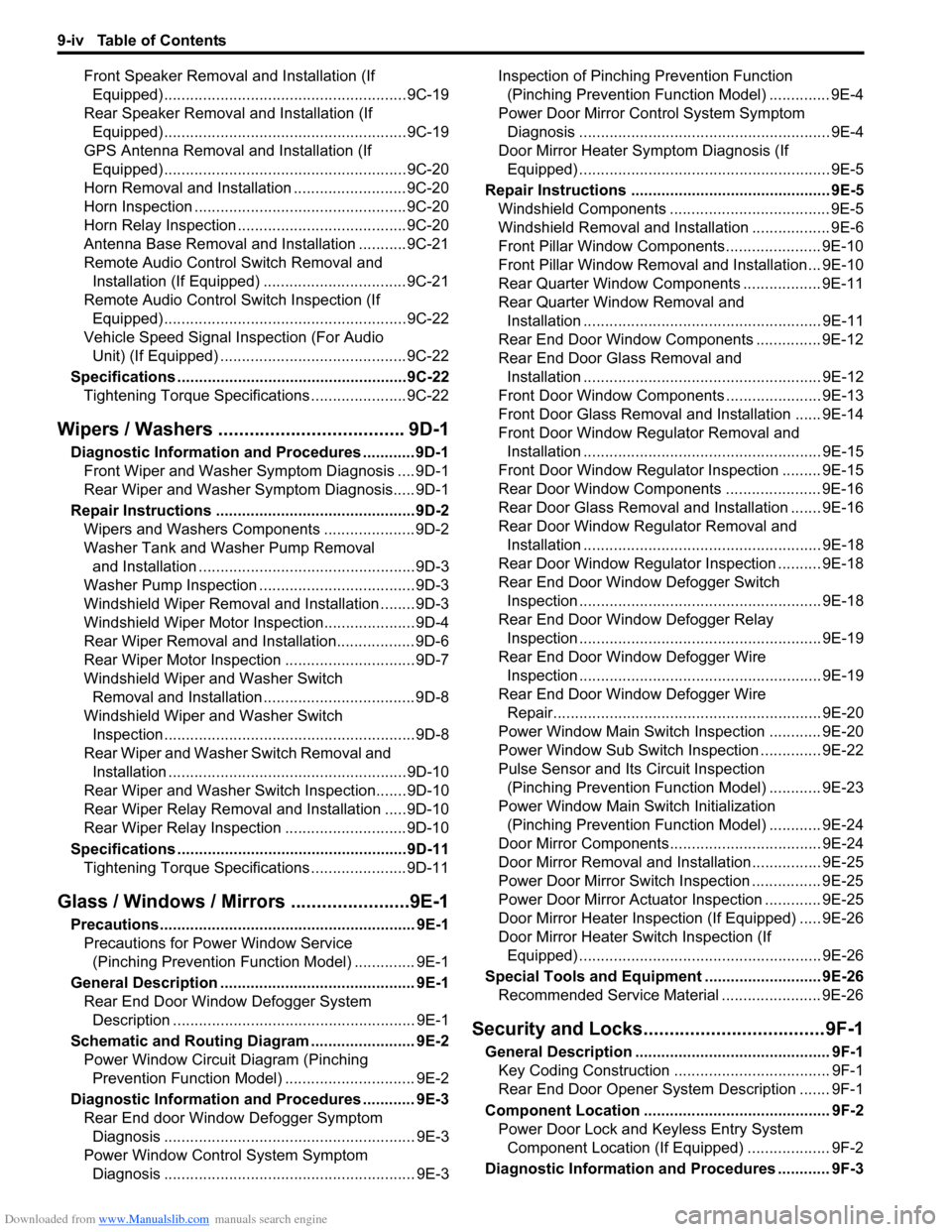
Downloaded from www.Manualslib.com manuals search engine 9-iv Table of Contents
Front Speaker Removal and Installation (If
Equipped) ........................................................9C-19
Rear Speaker Removal and Installation (If
Equipped) ........................................................9C-19
GPS Antenna Removal and Installation (If
Equipped) ........................................................9C-20
Horn Removal and Installation ..........................9C-20
Horn Inspection .................................................9C-20
Horn Relay Inspection .......................................9C-20
Antenna Base Removal and Installation ...........9C-21
Remote Audio Control Switch Removal and
Installation (If Equipped) .................................9C-21
Remote Audio Control Switch Inspection (If
Equipped) ........................................................9C-22
Vehicle Speed Signal Inspection (For Audio
Unit) (If Equipped) ...........................................9C-22
Specifications .....................................................9C-22
Tightening Torque Specifications ......................9C-22
Wipers / Washers .................................... 9D-1
Diagnostic Information and Procedures ............ 9D-1
Front Wiper and Washer Symptom Diagnosis ....9D-1
Rear Wiper and Washer Symptom Diagnosis..... 9D-1
Repair Instructions ..............................................9D-2
Wipers and Washers Components .....................9D-2
Washer Tank and Washer Pump Removal
and Installation ..................................................9D-3
Washer Pump Inspection ....................................9D-3
Windshield Wiper Removal and Installation ........9D-3
Windshield Wiper Motor Inspection.....................9D-4
Rear Wiper Removal and Installation.................. 9D-6
Rear Wiper Motor Inspection ..............................9D-7
Windshield Wiper and Washer Switch
Removal and Installation ................................... 9D-8
Windshield Wiper and Washer Switch
Inspection .......................................................... 9D-8
Rear Wiper and Washer Switch Removal and
Installation .......................................................9D-10
Rear Wiper and Washer Switch Inspection.......9D-10
Rear Wiper Relay Removal and Installation .....9D-10
Rear Wiper Relay Inspection ............................9D-10
Specifications .....................................................9D-11
Tightening Torque Specifications ......................9D-11
Glass / Windows / Mirrors .......................9E-1
Precautions........................................................... 9E-1
Precautions for Power Window Service
(Pinching Prevention Function Model) .............. 9E-1
General Description ............................................. 9E-1
Rear End Door Window Defogger System
Description ........................................................ 9E-1
Schematic and Routing Diagram ........................ 9E-2
Power Window Circuit Diagram (Pinching
Prevention Function Model) .............................. 9E-2
Diagnostic Information and Procedures ............ 9E-3
Rear End door Window Defogger Symptom
Diagnosis .......................................................... 9E-3
Power Window Control System Symptom
Diagnosis .......................................................... 9E-3Inspection of Pinching Prevention Function
(Pinching Prevention Function Model) .............. 9E-4
Power Door Mirror Control System Symptom
Diagnosis .......................................................... 9E-4
Door Mirror Heater Symptom Diagnosis (If
Equipped) .......................................................... 9E-5
Repair Instructions .............................................. 9E-5
Windshield Components ..................................... 9E-5
Windshield Removal and Installation .................. 9E-6
Front Pillar Window Components...................... 9E-10
Front Pillar Window Removal and Installation... 9E-10
Rear Quarter Window Components .................. 9E-11
Rear Quarter Window Removal and
Installation ....................................................... 9E-11
Rear End Door Window Components ............... 9E-12
Rear End Door Glass Removal and
Installation ....................................................... 9E-12
Front Door Window Components ...................... 9E-13
Front Door Glass Removal and Installation ...... 9E-14
Front Door Window Regulator Removal and
Installation ....................................................... 9E-15
Front Door Window Regulator Inspection ......... 9E-15
Rear Door Window Components ...................... 9E-16
Rear Door Glass Removal and Installation ....... 9E-16
Rear Door Window Regulator Removal and
Installation ....................................................... 9E-18
Rear Door Window Regulator Inspection .......... 9E-18
Rear End Door Window Defogger Switch
Inspection ........................................................ 9E-18
Rear End Door Window Defogger Relay
Inspection ........................................................ 9E-19
Rear End Door Window Defogger Wire
Inspection ........................................................ 9E-19
Rear End Door Window Defogger Wire
Repair.............................................................. 9E-20
Power Window Main Switch Inspection ............ 9E-20
Power Window Sub Switch Inspection .............. 9E-22
Pulse Sensor and Its Circuit Inspection
(Pinching Prevention Function Model) ............ 9E-23
Power Window Main Switch Initialization
(Pinching Prevention Function Model) ............ 9E-24
Door Mirror Components................................... 9E-24
Door Mirror Removal and Installation................ 9E-25
Power Door Mirror Switch Inspection ................ 9E-25
Power Door Mirror Actuator Inspection ............. 9E-25
Door Mirror Heater Inspection (If Equipped) ..... 9E-26
Door Mirror Heater Switch Inspection (If
Equipped) ........................................................ 9E-26
Special Tools and Equipment ........................... 9E-26
Recommended Service Material ....................... 9E-26
Security and Locks...................................9F-1
General Description ............................................. 9F-1
Key Coding Construction .................................... 9F-1
Rear End Door Opener System Description ....... 9F-1
Component Location ........................................... 9F-2
Power Door Lock and Keyless Entry System
Component Location (If Equipped) ................... 9F-2
Diagnostic Information and Procedures ............ 9F-3
Page 1165 of 1556
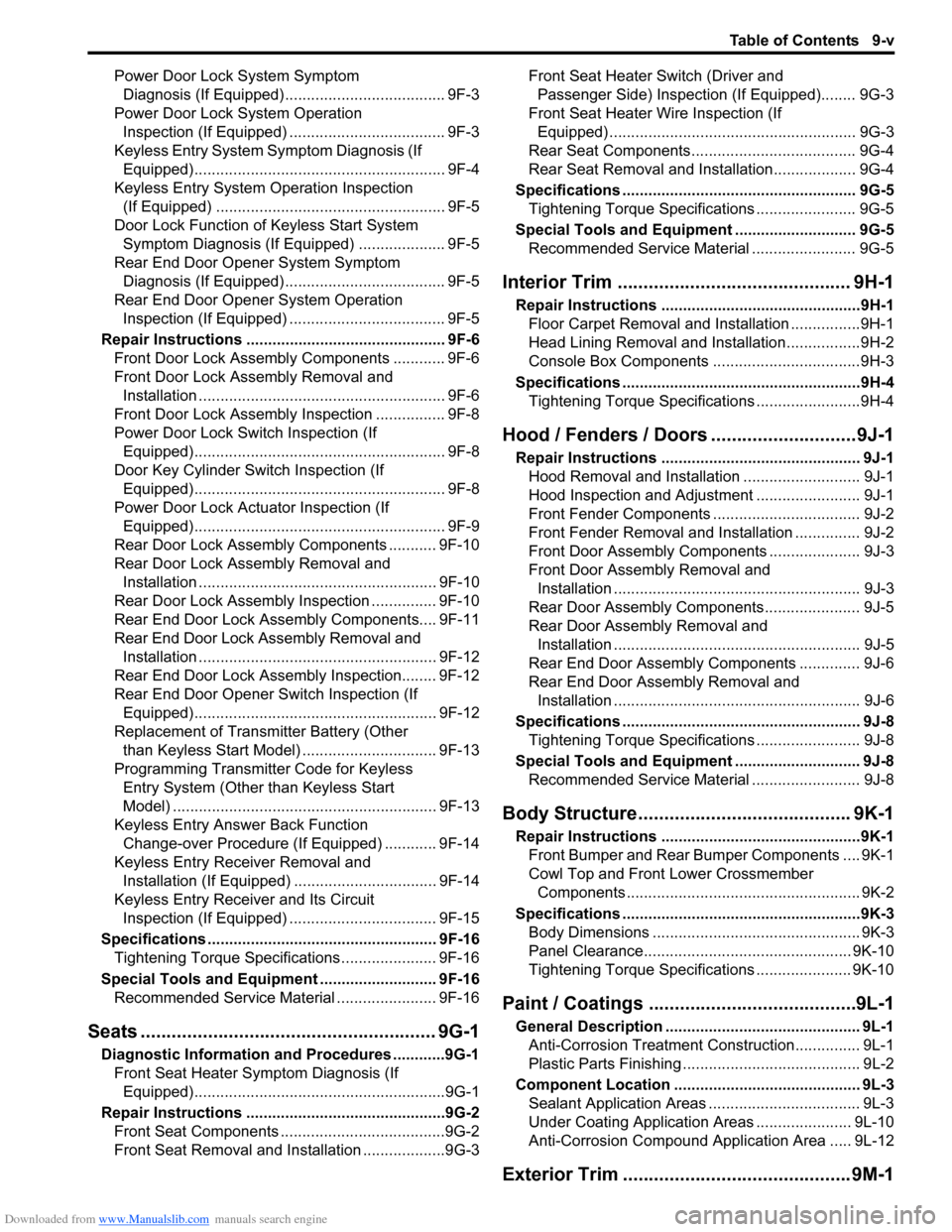
Downloaded from www.Manualslib.com manuals search engine Table of Contents 9-v
Power Door Lock System Symptom
Diagnosis (If Equipped)..................................... 9F-3
Power Door Lock System Operation
Inspection (If Equipped) .................................... 9F-3
Keyless Entry System Symptom Diagnosis (If
Equipped).......................................................... 9F-4
Keyless Entry System Operation Inspection
(If Equipped) ..................................................... 9F-5
Door Lock Function of Keyless Start System
Symptom Diagnosis (If Equipped) .................... 9F-5
Rear End Door Opener System Symptom
Diagnosis (If Equipped)..................................... 9F-5
Rear End Door Opener System Operation
Inspection (If Equipped) .................................... 9F-5
Repair Instructions .............................................. 9F-6
Front Door Lock Assembly Components ............ 9F-6
Front Door Lock Assembly Removal and
Installation ......................................................... 9F-6
Front Door Lock Assembly Inspection ................ 9F-8
Power Door Lock Switch Inspection (If
Equipped).......................................................... 9F-8
Door Key Cylinder Switch Inspection (If
Equipped).......................................................... 9F-8
Power Door Lock Actuator Inspection (If
Equipped).......................................................... 9F-9
Rear Door Lock Assembly Components ........... 9F-10
Rear Door Lock Assembly Removal and
Installation ....................................................... 9F-10
Rear Door Lock Assembly Inspection ............... 9F-10
Rear End Door Lock Assembly Components.... 9F-11
Rear End Door Lock Assembly Removal and
Installation ....................................................... 9F-12
Rear End Door Lock Assembly Inspection........ 9F-12
Rear End Door Opener Switch Inspection (If
Equipped)........................................................ 9F-12
Replacement of Transmitter Battery (Other
than Keyless Start Model) ............................... 9F-13
Programming Transmitter Code for Keyless
Entry System (Other than Keyless Start
Model) ............................................................. 9F-13
Keyless Entry Answer Back Function
Change-over Procedure (If Equipped) ............ 9F-14
Keyless Entry Receiver Removal and
Installation (If Equipped)................................. 9F-14
Keyless Entry Receiver and Its Circuit
Inspection (If Equipped) .................................. 9F-15
Specifications..................................................... 9F-16
Tightening Torque Specifications ...................... 9F-16
Special Tools and Equipment ........................... 9F-16
Recommended Service Material ....................... 9F-16
Seats ......................................................... 9G-1
Diagnostic Information and Procedures ............9G-1
Front Seat Heater Symptom Diagnosis (If
Equipped)..........................................................9G-1
Repair Instructions ..............................................9G-2
Front Seat Components ......................................9G-2
Front Seat Removal and Installation ...................9G-3Front Seat Heater Switch (Driver and
Passenger Side) Inspection (If Equipped)........ 9G-3
Front Seat Heater Wire Inspection (If
Equipped) ......................................................... 9G-3
Rear Seat Components...................................... 9G-4
Rear Seat Removal and Installation................... 9G-4
Specifications ...................................................... 9G-5
Tightening Torque Specifications ....................... 9G-5
Special Tools and Equipment ............................ 9G-5
Recommended Service Material ........................ 9G-5
Interior Trim ............................................. 9H-1
Repair Instructions ..............................................9H-1
Floor Carpet Removal and Installation ................9H-1
Head Lining Removal and Installation.................9H-2
Console Box Components ..................................9H-3
Specifications .......................................................9H-4
Tightening Torque Specifications ........................9H-4
Hood / Fenders / Doors ............................ 9J-1
Repair Instructions .............................................. 9J-1
Hood Removal and Installation ........................... 9J-1
Hood Inspection and Adjustment ........................ 9J-1
Front Fender Components .................................. 9J-2
Front Fender Removal and Installation ............... 9J-2
Front Door Assembly Components ..................... 9J-3
Front Door Assembly Removal and
Installation ......................................................... 9J-3
Rear Door Assembly Components...................... 9J-5
Rear Door Assembly Removal and
Installation ......................................................... 9J-5
Rear End Door Assembly Components .............. 9J-6
Rear End Door Assembly Removal and
Installation ......................................................... 9J-6
Specifications ....................................................... 9J-8
Tightening Torque Specifications ........................ 9J-8
Special Tools and Equipment ............................. 9J-8
Recommended Service Material ......................... 9J-8
Body Structure......................................... 9K-1
Repair Instructions ..............................................9K-1
Front Bumper and Rear Bumper Components .... 9K-1
Cowl Top and Front Lower Crossmember
Components ...................................................... 9K-2
Specifications .......................................................9K-3
Body Dimensions ................................................ 9K-3
Panel Clearance................................................ 9K-10
Tightening Torque Specifications ...................... 9K-10
Paint / Coatings ........................................9L-1
General Description ............................................. 9L-1
Anti-Corrosion Treatment Construction............... 9L-1
Plastic Parts Finishing ......................................... 9L-2
Component Location ........................................... 9L-3
Sealant Application Areas ................................... 9L-3
Under Coating Application Areas ...................... 9L-10
Anti-Corrosion Compound Application Area ..... 9L-12
Exterior Trim ............................................ 9M-1
Page 1184 of 1556
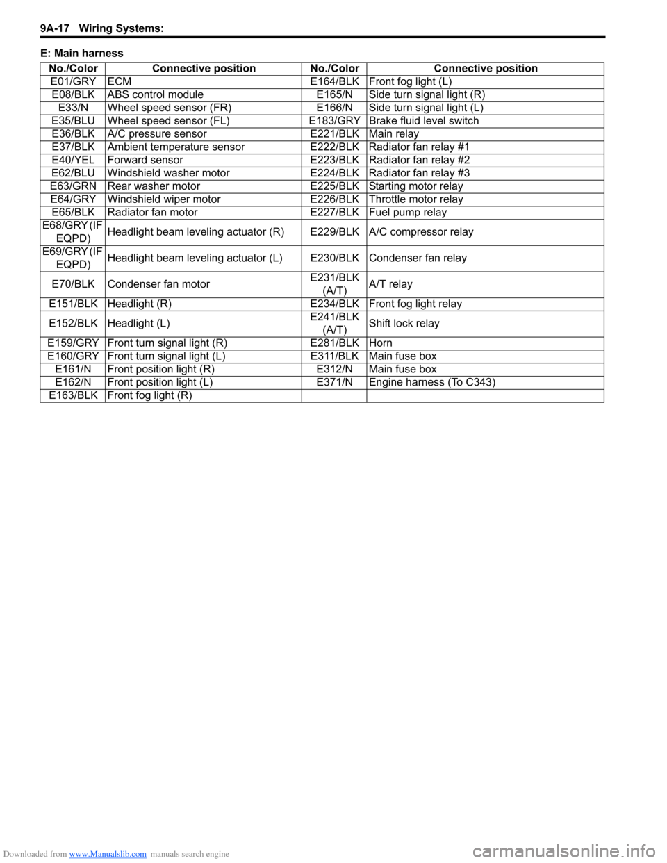
Downloaded from www.Manualslib.com manuals search engine 9A-17 Wiring Systems:
E: Main harness
No./Color Connective position No./Color Connective position
E01/GRY ECM E164/BLK Front fog light (L)
E08/BLK ABS control module E165/N Side turn signal light (R)
E33/N Wheel speed sensor (FR) E166/N Side turn signal light (L)
E35/BLU Wheel speed sensor (FL)E183/GRY Brake fluid level switch
E36/BLK A/C pressure sensor E221/BLK Main relay
E37/BLK Ambient temperature sensor E222/BLK Radiator fan relay #1
E40/YEL Forward sensor E223/BLK Radiator fan relay #2
E62/BLU Windshield washer motor E224/BLK Radiator fan relay #3
E63/GRN Rear washer motor E225/BLK Starting motor relay
E64/GRY Windshield wiper motor E226/BLK Throttle motor relay
E65/BLK Radiator fan motor E227/BLK Fuel pump relay
E68/GRY (IF
EQPD)Headlight beam leveling actuator (R) E229/BLK A/C compressor relay
E69/GRY (IF
EQPD)Headlight beam leveling actuator (L) E230/BLK Condenser fan relay
E70/BLK Condenser fan motorE231/BLK
(A/T)A/T relay
E151/BLK Headlight (R) E234/BLK Front fog light relay
E152/BLK Headlight (L)E241/BLK
(A/T)Shift lock relay
E159/GRY Front turn signal light (R) E281/BLK Horn
E160/GRY Front turn signal light (L) E311/BLK Main fuse box
E161/N Front position light (R) E312/N Main fuse box
E162/N Front position light (L) E371/N Engine harness (To C343)
E163/BLK Front fog light (R)