2006 SUZUKI SX4 Actuator
[x] Cancel search: ActuatorPage 1347 of 1556
Downloaded from www.Manualslib.com manuals search engine Lighting Systems: 9B-28
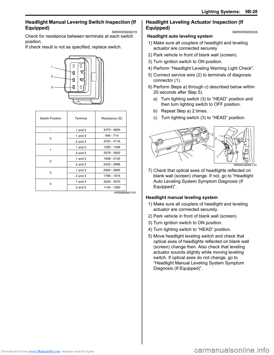
Headlight Manual Levering Switch Inspection (If
Equipped)
S6RW0D9206019
Check for resistance between terminals at each switch
position.
If check result is not as specified, replace switch.
Headlight Leveling Actuator Inspection (If
Equipped)
S6RW0D9206026
Headlight auto leveling system
1) Make sure all couplers of headlight and leveling
actuator are connected securely.
2) Park vehicle in front of blank wall (screen).
3) Turn ignition switch to ON position.
4) Perform “Headlight Leveling Warning Light Check”.
5) Connect service wire (2) to terminals of diagnosis
connector (1).
6) Perform Steps a) through c) described below within
20 seconds after Step 5).
a) Turn lighting switch (3) to “HEAD” position and
then turn lighting switch to OFF position.
b) Repeat Step a) 2 times.
c) Turn lighting switch (3) to “HEAD” position.
7) Check that optical axes of headlights reflected on
blank wall (screen) change. If not, go to “Headlight
Auto Leveling System Symptom Diagnosis (If
Equipped)”.
Headlight manual leveling system
1) Make sure all couplers of headlight and leveling
actuator are connected securely.
2) Park vehicle in front of blank wall (screen).
3) Turn ignition switch to ON position.
4) Turn lighting switch to “HEAD” position.
5) Move headlight leveling switch and check that
optical axes of headlights reflected on blank wall
(screen) change then. Also check that leveling
actuator sounds slightly while moving leveling
switch. If optical axes do not change, go to
“Headlight Manual Leveling System Symptom
Diagnosis (If Equipped)”.
1
2
3
Switch Position
0Terminal Resistance ( )
-
1
2
3
41 and 24370 - 4830
1 and 3
2 and 3
1 and 3
2 and 3
1 and 3
2 and 3
1 and 3
2 and 3
1 and 3
2 and 3646 - 714
3724 - 4116
3078 - 3402 1292 - 1428
1938 - 2142
2584 - 2856
3230 - 3570 2432 - 2688
1786 - 1974
1140 - 1260
I4RS0B920012-01
3
1
2
I6RW0C920021-01
Page 1389 of 1556
Downloaded from www.Manualslib.com manuals search engine Glass / Windows / Mirrors: 9E-4
Inspection of Pinching Prevention Function (Pinching Prevention Function Model)S6RW0D9504032
1) Open driver side door glass fully.
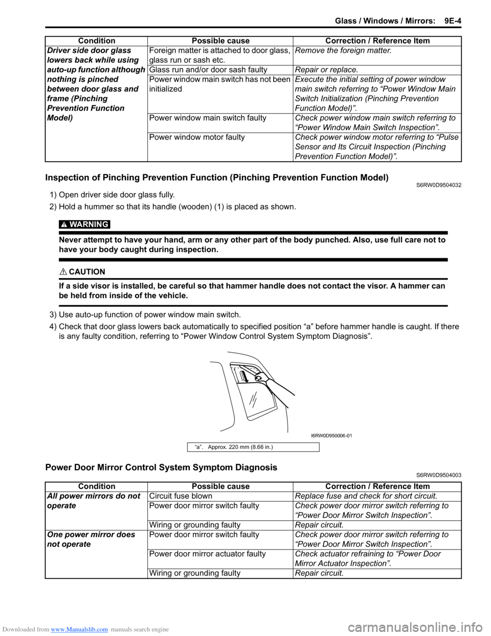
2) Hold a hummer so that its handle (wooden) (1) is placed as shown.
WARNING!
Never attempt to have your hand, arm or any other part of the body punched. Also, use full care not to
have your body caught during inspection.
CAUTION!
If a side visor is installed, be careful so that hammer handle does not contact the visor. A hammer can
be held from inside of the vehicle.
3) Use auto-up function of power window main switch.
4) Check that door glass lowers back automatically to specified position “a” before hammer handle is caught. If there
is any faulty condition, referring to “Power Window Control System Symptom Diagnosis”.
Power Door Mirror Control System Symptom DiagnosisS6RW0D9504003
Driver side door glass
lowers back while using
auto-up function although
nothing is pinched
between door glass and
frame (Pinching
Prevention Function
Model)Foreign matter is attached to door glass,
glass run or sash etc.Remove the foreign matter.
Glass run and/or door sash faultyRepair or replace.
Power window main switch has not been
initializedExecute the initial setting of power window
main switch referring to “Power Window Main
Switch Initialization (Pinching Prevention
Function Model)”.
Power window main switch faultyCheck power window main switch referring to
“Power Window Main Switch Inspection”.
Power window motor faultyCheck power window motor referring to “Pulse
Sensor and Its Circuit Inspection (Pinching
Prevention Function Model)”. Condition Possible cause Correction / Reference Item
“a”. Approx. 220 mm (8.66 in.)
I6RW0D950006-01
Condition Possible cause Correction / Reference Item
All power mirrors do not
operateCircuit fuse blownReplace fuse and check for short circuit.
Power door mirror switch faultyCheck power door mirror switch referring to
“Power Door Mirror Switch Inspection”.
Wiring or grounding faultyRepair circuit.
One power mirror does
not operatePower door mirror switch faultyCheck power door mirror switch referring to
“Power Door Mirror Switch Inspection”.
Power door mirror actuator faultyCheck actuator refraining to “Power Door
Mirror Actuator Inspection”.
Wiring or grounding faultyRepair circuit.
Page 1410 of 1556
Downloaded from www.Manualslib.com manuals search engine 9E-25 Glass / Windows / Mirrors:
Door Mirror Removal and InstallationS6RW0D9506024
When removing or installing door mirror, refer to the
figure in “Door Mirror Components”.
Power Door Mirror Switch InspectionS6RW0D9506025
1) Remove driver side door trim referring to step 1) to
3) of “Front Door Glass Removal and Installation”.
2) Remove power window main switch from door trim.
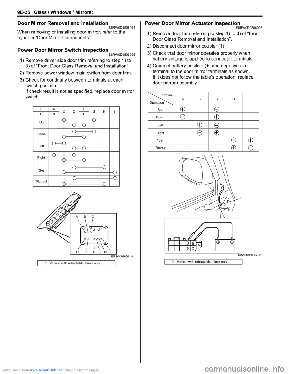
3) Check for continuity between terminals at each
switch position.
If check result is not as specified, replace door mirror
switch.
Power Door Mirror Actuator InspectionS6RW0D9506026
1) Remove door trim referring to step 1) to 3) of “Front
Door Glass Removal and Installation”.
2) Disconnect door mirror coupler (1).
3) Check that door mirror operates properly when
battery voltage is applied to connector terminals.
4) Connect battery positive (+) and negative (–)
terminal to the door mirror terminals as shown.
If it does not follow the table’s operation, replace
door mirror assembly.
*: Vehicle with retractable mirror only
ABC
DEFG
A
BC
DE
FG
Up
Down
Left
Right
L
RH
I
*Set
*Retract
HII5RS0C950004-01
*: Vehicle with retractable mirror only
A
B
C1 Operation
Terminal
Up
Down
Left
Right
*Set
*RetractCDE B A
D
E
I6RW0D950007-01
Page 1413 of 1556
Downloaded from www.Manualslib.com manuals search engine Security and Locks: 9F-2
Component Location
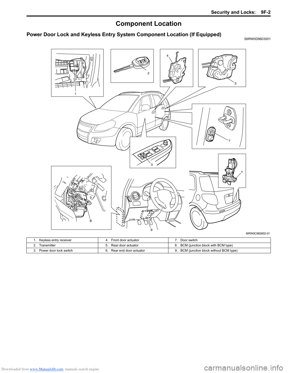
Power Door Lock and Keyless Entry System Component Location (If Equipped)S6RW0D9603001
3
7
4
5
6
1
2
8
9I6RW0C960002-01
1. Keyless entry receiver 4. Front door actuator 7. Door switch
2. Transmitter 5. Rear door actuator 8. BCM (junction block with BCM type)
3. Power door lock switch 6. Rear end door actuator 9. BCM (junction block without BCM type)
Page 1414 of 1556
Downloaded from www.Manualslib.com manuals search engine 9F-3 Security and Locks:
Diagnostic Information and Procedures
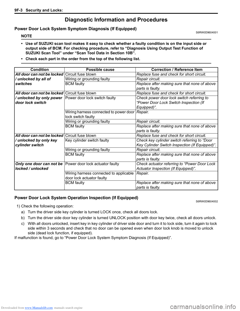
Power Door Lock System Symptom Diagnosis (If Equipped)S6RW0D9604001
NOTE
• Use of SUZUKI scan tool makes it easy to check whether a faulty condition is on the input side or
output side of BCM. For checking procedure, refer to “Diagnosis Using Output Test Function of
SUZUKI Scan Tool” under “Scan Tool Data in Section 10B”.
• Check each part in the order from the top of the following list.
Power Door Lock System Operation Inspection (If Equipped)S6RW0D9604002
1) Check the following operation:
a) Turn the driver side key cylinder is turned LOCK once, check all doors lock.
b) Turn the driver side door key cylinder is turned UNLOCK position with door key twice, check all doors unlock.
c) With all doors unlocked, insert key in key cylinder of driver side door and turn it to lock side, turn it again to lock
side within 3 seconds and check that no door can be opened even when door lock knob is moved to unlock
side (dead lock function, if equipped).
If malfunction is found, go to “Power Door Lock System Symptom Diagnosis (If Equipped)”. Condition Possible cause Correction / Reference Item
All door can not be locked
/ unlocked by all of
switchesCircuit fuse blownReplace fuse and check for short circuit.
Wiring or grounding faultyRepair circuit.
BCM faultyReplace after making sure that none of above
parts is faulty.
All door can not be locked
/ unlocked by only power
door lock switchCircuit fuse blownReplace fuse and check for short circuit.
Power door lock switch faultyCheck power door lock switch referring to
“Power Door Lock Switch Inspection (If
Equipped)”.
Wiring harness connected to power door
lock switch faultyRepair.
Wiring or grounding faultyRepair circuit.
BCM faultyReplace after making sure that none of above
parts is faulty.
All door can not be locked
/ unlocked by only key
cylinder switchCircuit fuse blownReplace fuse and check for short circuit.
Key cylinder switch faultyCheck key cylinder switch referring to “Door
Key Cylinder Switch Inspection (If Equipped)”.
Wiring or grounding faultyRepair circuit.
BCM faultyReplace after making sure that none of above
parts is faulty.
Only one door can not be
locked / unlockedPower door lock actuator faultyCheck actuator referring to “Power Door Lock
Actuator Inspection (If Equipped)”.
Wiring harness connected to applicable
door lock actuator faultyRepair.
BCM faultyReplace after making sure that none of above
parts is faulty.
Page 1416 of 1556
Downloaded from www.Manualslib.com manuals search engine 9F-5 Security and Locks:
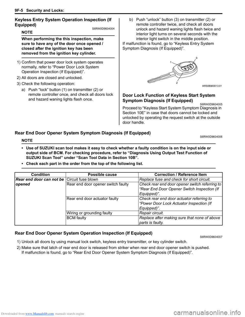
Keyless Entry System Operation Inspection (If
Equipped)
S6RW0D9604004
NOTE
When performing the this inspection, make
sure to have any of the door once opened /
closed after the ignition key has been
removed from the ignition key cylinder.
1) Confirm that power door lock system operates
normally, refer to “Power Door Lock System
Operation Inspection (If Equipped)”.
2) All doors are closed and unlocked.
3) Check the following operation:
a) Push “lock” button (1) on transmitter (2) or
remote controller once, and check all doors lock
and hazard waning lights flash once.b) Push “unlock” button (3) on transmitter (2) or
remote controller twice, and check all doors
unlock and hazard waning lights flash twice and
interior light turns on several seconds with the
interior light switch in the middle position.
If malfunction is found, go to “Keyless Entry System
Symptom Diagnosis (If Equipped)”.
Door Lock Function of Keyless Start System
Symptom Diagnosis (If Equipped)
S6RW0D9604005
Proceed to “Keyless Start System Symptom Diagnosis in
Section 10E” in case that doors cannot be locked and
unlocked by operating the request switch at the outside
door handle.
Rear End Door Opener System Symptom Diagnosis (If Equipped)S6RW0D9604006
NOTE
• Use of SUZUKI scan tool makes it easy to check whether a faulty condition is on the input side or
output side of BCM. For checking procedure, refer to “Diagnosis Using Output Test Function of
SUZUKI Scan Tool” under “Scan Tool Data in Section 10B”.
• Check each part in the order from the top of the following list.
Rear End Door Opener System Operation Inspection (If Equipped)S6RW0D9604007
1) Unlock all doors by using manual lock switch, keyless entry transmitter, or key cylinder switch.
2) Make sure that latch of rear end door is released from striker when rear end door opener switch is pushed.
If malfunction is found, go to “Rear End Door Opener System Symptom Diagnosis (If Equipped)”.
1
3
2I4RS0B960013-01
Condition Possible cause Correction / Reference Item
Rear end door can not be
openedCircuit fuse blownReplace fuse and check for short circuit.
Rear end door opener switch faultyCheck rear end door opener switch referring to
“Rear End Door Opener Switch Inspection (If
Equipped)”.
Rear end door actuator faultyCheck rear end door actuator referring to
“Power Door Lock Actuator Inspection (If
Equipped)”.
Wiring or grounding faultyRepair circuit.
BCM faultyReplace after making sure that none of above
parts is faulty.
Page 1420 of 1556
Downloaded from www.Manualslib.com manuals search engine 9F-9 Security and Locks:
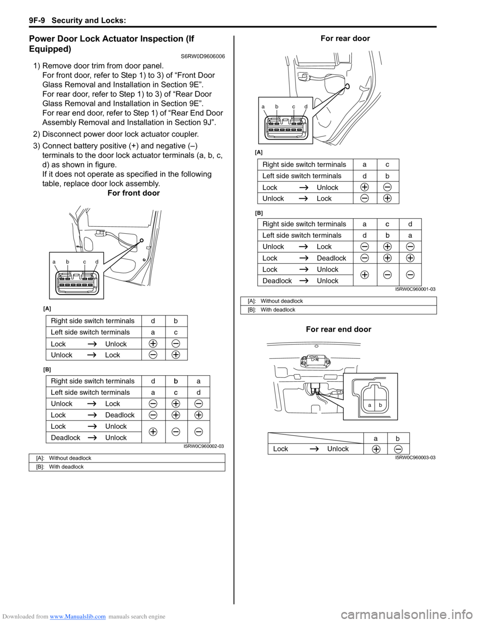
Power Door Lock Actuator Inspection (If
Equipped)
S6RW0D9606006
1) Remove door trim from door panel.
For front door, refer to Step 1) to 3) of “Front Door
Glass Removal and Installation in Section 9E”.
For rear door, refer to Step 1) to 3) of “Rear Door
Glass Removal and Installation in Section 9E”.
For rear end door, refer to Step 1) of “Rear End Door
Assembly Removal and Installation in Section 9J”.
2) Disconnect power door lock actuator coupler.
3) Connect battery positive (+) and negative (–)
terminals to the door lock actuator terminals (a, b, c,
d) as shown in figure.
If it does not operate as specified in the following
table, replace door lock assembly.
For front doorFor rear door
For rear end door
[A]: Without deadlock
[B]: With deadlock
ab cd
Right side switch terminals b
Unlock Lock
Lock Deadlock
Lock Unlock
Left side switch terminals c
Unlock
Deadlock
[A]
[B]
Right side switch terminals bd
Unlock Lock
Lock Unlock
Left side switch terminals ca
acd dba
I5RW0C960002-03
[A]: Without deadlock
[B]: With deadlock
ab cd
Right side switch terminals c
Unlock Lock
Lock Deadlock
Lock Unlock
Left side switch terminals b
Unlock
Deadlock
[B] [A]
Right side switch terminals
b d
Unlock Lock
Lock Unlock
Left side switch terminalsc a
dba acd
I5RW0C960001-03
ab
Lock Unlock
a
b
I5RW0C960003-03
Page 1474 of 1556
Downloaded from www.Manualslib.com manuals search engine 10B-1 Body Electrical Control System:
Control Systems
Body Electrical Control System
Precautions
Precautions in Diagnosing TroubleS6RW0DA200001
• Diagnostic information stored in BCM memory can be cleared as well as checked by using SUZUKI scan tool.
Before using scan tool, read its Operator’s (Instruction) Manual carefully to have good understanding as to what
functions are available and how to use it.
• Be sure to read “Precautions for Electrical Circuit Service in Section 00” before inspection and observe what is
written there.
• Communication of ECM, TCM (A/T model), ABS control module, 4WD control module (if equipped), keyless start
control module (if equipped), combination meter and BCM is established by CAN (Controller Area Network). For
detail of CAN communication for BCM, refer to “CAN Communication System Description”. Therefore, handle CAN
communication line with care referring to “Precaution for CAN Communication System in Section 00”.
General Description
BCM General DescriptionS6RW0DA201001
The Body electrical Control Module (BCM) is
incorporated in junction block. Do not attempt removal of
BCM from junction block as it may cause contact failure.
The BCM incorporates relays and controllers which are
used for the following systems and controls them.
• Power door lock (if equipped)
• Keyless entry (if equipped)
• Door lock function of keyless start system (if
equipped)
• Rear wiper
• Combination meter
• Interior light• Warning buzzer
• Rear end door window defogger and door mirror
heater (if equipped)
• Rear end door opener (if equipped)
• Theft deterrent light
Also, the BCM has a function to cause the interior light
and open door warning light in the combination meter to
turn off when any door is left open for longer than 15
minutes to reduce wasteful battery consumption.
In addition, it is possible to check operation of actuator
which is controlled by BCM by using the output test
function of SUZUKI scan tool to operate actuator
simulatively.
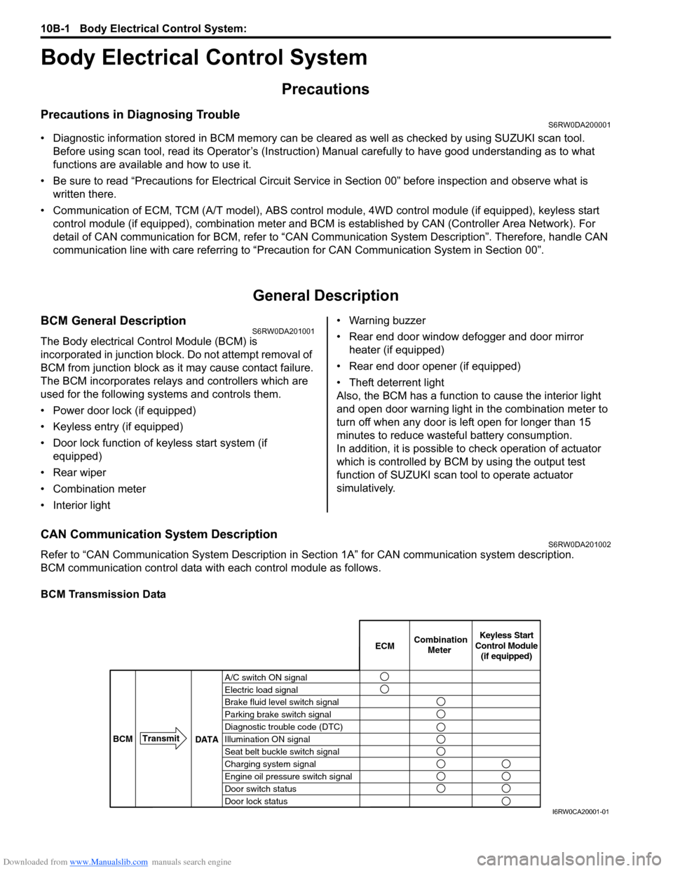
CAN Communication System DescriptionS6RW0DA201002
Refer to “CAN Communication System Description in Section 1A” for CAN communication system description.
BCM communication control data with each control module as follows.
BCM Transmission Data
A/C switch ON signal
Electric load signal
Brake fluid level switch signal
Parking brake switch signal
Diagnostic trouble code (DTC)
Illumination ON signal
Seat belt buckle switch signal
Charging system signal
Engine oil pressure switch signal
Door switch status
Door lock statusECMKeyless Start
Control Module
(if equipped) Combination
Meter
BCMTransmit
DATA
I6RW0CA20001-01