2006 SUZUKI SX4 valve body
[x] Cancel search: valve bodyPage 782 of 1556

Downloaded from www.Manualslib.com manuals search engine 5A-134 Automatic Transmission/Transaxle:
Valve Body Assembly Disassembly and
Reassembly
S6RW0D5106051
CAUTION!
When replacing pressure control solenoid
valve and/or TCC pressure control solenoid
valve, it is strictly required to replace it
together with valve body assembly as a set.
Replacing pressure control solenoid valve
and/or TCC pressure control solenoid valve
independently may cause excessive shift
shock.
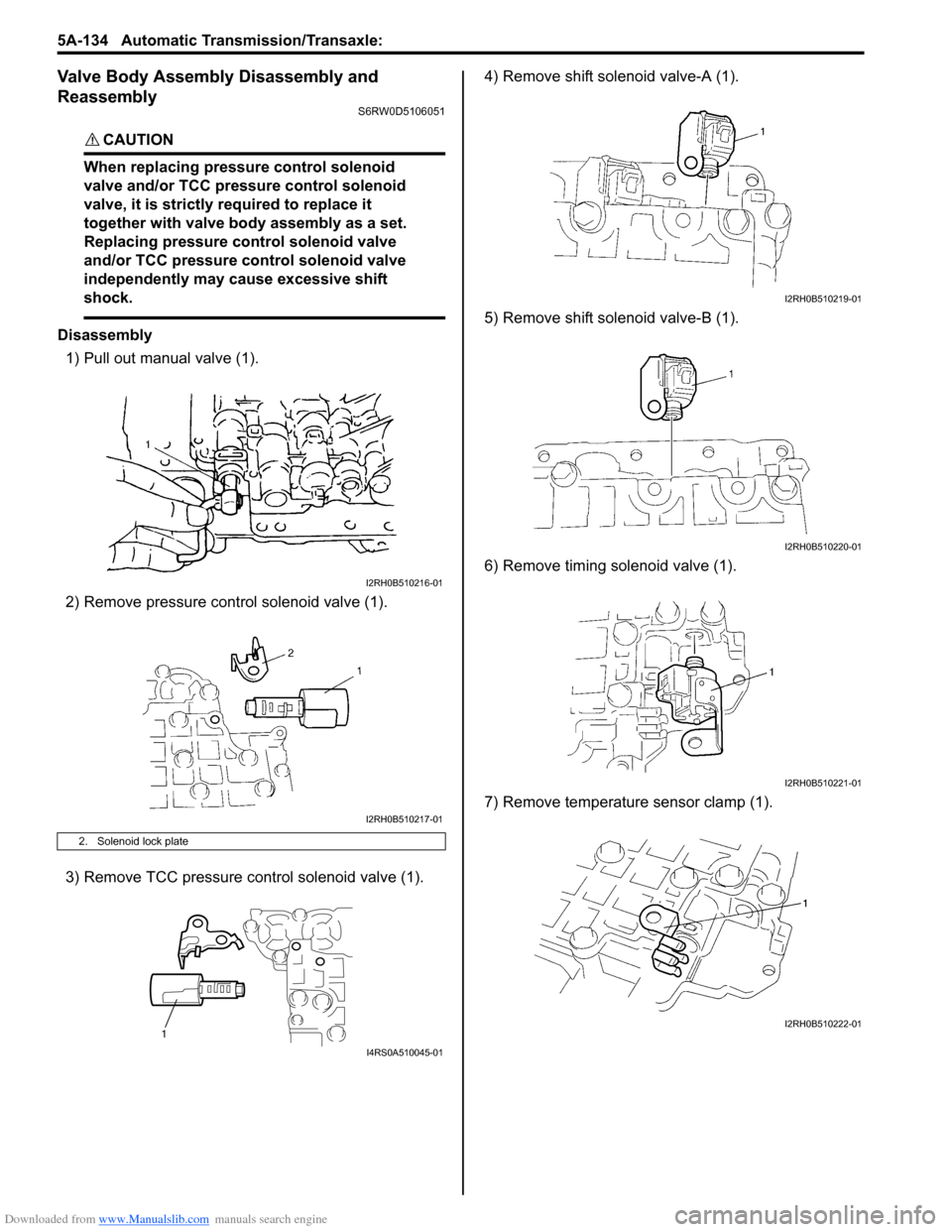
Disassembly
1) Pull out manual valve (1).
2) Remove pressure control solenoid valve (1).
3) Remove TCC pressure control solenoid valve (1).4) Remove shift solenoid valve-A (1).
5) Remove shift solenoid valve-B (1).
6) Remove timing solenoid valve (1).
7) Remove temperature sensor clamp (1).
2. Solenoid lock plate
I2RH0B510216-01
I2RH0B510217-01
1
I4RS0A510045-01
I2RH0B510219-01
I2RH0B510220-01
I2RH0B510221-01
I2RH0B510222-01
Page 783 of 1556

Downloaded from www.Manualslib.com manuals search engine Automatic Transmission/Transaxle: 5A-135
Reassembly
Reverse disassembly procedure for assembly, noting the
following points.
• Shift solenoid valve-A and -B are identical
• After applying A/T fluid to new O-rings, fit them to
solenoid valves, then install solenoid valves to valve
body.
• Tighten solenoid valve bolts to specified torque
Tightening torque
Solenoid valve bolt (a): 11 N·m (1.1 kgf-m, 8.0 lb-ft)
Solenoid valve bolt specification
Differential Assembly ComponentsS6RW0D5106052
Bolt Length “a” Pieces
A (1) 49 mm (1.93 in.) 5
B (2) 20 mm (0.79 in.) 1
C (3) 60 mm (2.36 in.) 1
1
1 1
3
2
"a"
I4RS0A510046-01
I5RW0C510064-01
1. Differential side RH bearing 5. Side bearing shim : Apply automatic transaxle fluid.
2. Output shaft speed sensor (VSS) drive gear 6. Final gear bolt : 78 N⋅m (7.8 kgf-m, 56.5 lb-ft)
3. Differential case subassembly 7. Side bearing cup : Do not reuse.
4. Final gear 8. Differential side LH bearing
Page 805 of 1556

Downloaded from www.Manualslib.com manuals search engine Automatic Transmission/Transaxle: 5A-157
72) After applying A/T fluid to new O-ring, fit it to valve
body harness connector (3), then install valve body
harness to transaxle case.
CAUTION!
When put valve body harness (1) into
transaxle case, take care not to damage
transmission fluid temperature sensor (2) at
narrow entrance of case.
Careless sensor treatment might cause
sensor malfunction.
Tightening torque
Valve body harness connector bolt (a): 5.5 N·m (
0.55 kgf-m, 4.0 lb-ft)
73) Install manual valve rod (1) to manual valve lever (3)
and then install valve body assembly (2) to transaxle
case.
74) Tighten valve body bolts to specified torque.
Tightening torque
Valve body bolt: 11 N·m (1.1 kgf-m, 8.0 lb-ft)Valve body bolt length
75) Connect solenoid connectors to solenoid valves
identifying their installing positions by wire colors,
and install transmission fluid temperature sensor to
its clamp.
Solenoid valve coupler specification
I2RH0B510321-01
I2RH0B510322-01
Bolt Length “a” Pieces
A (1) 20 mm (0.79 in.) 6
B (2) 28 mm (1.10 in.) 5
C (3) 49 mm (1.93 in.) 1
D (4) 36 mm (1.42 in.) 1
E (5) 40 mm (1.58 in.) 1
Solenoid valve coupler Wire color
Shift solenoid valve-A (No.1) (1) White
Shift solenoid valve-B (No.2) (2) Black
Timing solenoid valve (3) Yellow
TCC solenoid valve (4)Light green /
Brown
Pressure control solenoid valve (5) Gray / Green
Transmission fluid temperature
sensor (6)Orange
I2RH0B510323-01
1 4
6
3
2
5
I5RW0C510067-02
Page 809 of 1556

Downloaded from www.Manualslib.com manuals search engine Automatic Transmission/Transaxle: 5A-161
Specifications
Tightening Torque SpecificationsS6RW0D5107001
NOTE
The specified tightening torque is also described in the following.
“Select Cable Components”
“Automatic Transaxle Unit Components”
“Automatic Transaxle Assembly Components”
“Oil Pump Assembly Components”
“Transaxle Rear Cover (O/D and 2nd Coast Brake Piston) Assembly Components”
“Valve Body Assembly Components”
“Differential Assembly Components”
Reference:
For the tightening torque of fastener not specified in this section, refer to “Fasteners Information in Section 0A”. Fastening partTightening torque
Note
N⋅mkgf-mlb-ft
A/T fluid drain plug 17 1.7 12.5�) / �) / �)
Transmission range sensor bolt 5.5 0.55 4.0�) / �)
Output shaft speed sensor (VSS) bolt 13 1.3 9.5�) / �)
Input shaft speed sensor bolt 5.5 0.55 4.0�) / �)
Valve body harness connector bolt 5.5 0.55 4.0�) / �)
Shift solenoid bolt 11 1.1 8.0�)
Oil strainer bolt 10 1.0 7.5�) / �)
Oil pan bolt 7.0 0.7 5.0�) / �)
Engine oil pan bolt 55 5.5 40.0�)
Transaxle and engine fastening bolt 85 8.5 61.5�)
Transaxle and engine fastening nut 85 8.5 61.5�)
Drive plate to torque converter bolt 19 1.9 14.0�)
Transaxle housing lower plate bolt 11 1.1 8.0�)
Oil pump subassembly bolt 10 1.0 7.5�)
Rear cover plug 7.5 0.75 5.5�)
Solenoid valve bolt 11 1.1 8.0�)
Final gear bolt 78 7.8 56.5�)
Torque converter housing plug 7.5 0.75 5.5�)
Lubrication tube clamp bolt 5.5 0.55 4.0�)
Fluid reservoir RH plate bolt 5.5 0.55 4.0�)
Torque converter housing bolt 33 3.3 24.0�) / �) / �)
Manual detent spring bolt 10 1.0 7.5�)
Parking lock pawl bracket bolt 7.5 0.75 5.5�)
Rear cover bolt 25 2.5 18.0�)
Fluid reservoir LH plate bolt 10 1.0 7.5�)
Oil pump assembly bolt 25 2.5 18.0�)
Transaxle case plug 7.5 0.75 5.5�)
Valve body bolt 11 1.1 8.0�)
Fluid cooler pipe union 25 2.5 18.0�)
Fluid cooler pipe union bolt 35 3.5 25.5�)
Fluid cooler pipe bracket bolt 10 1.0 7.5�)
Fluid filler tube bolt 10 1.0 7.5�)
Select cable bracket bolt 23 2.3 17.0�)
Select cable clamp bolt 13 1.3 9.5�)
Transmission range sensor lock nut 7 0.7 5.0�)
Manual select lever nut 13 1.3 9.5�)
Page 810 of 1556

Downloaded from www.Manualslib.com manuals search engine 5A-162 Automatic Transmission/Transaxle:
Special Tools and Equipment
Recommended Service MaterialS6RW0D5108001
NOTE
Required service material is also described in the following.
“Select Cable Components”
“Automatic Transaxle Assembly Components”
“Oil Pump Assembly Components”
“Direct Clutch Assembly Components”
“Forward and Reverse Clutch Assembly Components”
“2nd Brake Piston Assembly Components”
“Transaxle Rear Cover (O/D and 2nd Coast Brake Piston) Assembly Components”
“Countershaft Assembly Components”
“Valve Body Assembly Components”
“Differential Assembly Components”
Special ToolS6RW0D5108002
Material SUZUKI recommended product or Specification Note
Grease SUZUKI Super Grease A P/No.: 99000–25011�) / �)
SUZUKI Super Grease C P/No.: 99000–25030�) / �) / �) / �) / �) / �)
Sealant SUZUKI Bond No.1216B P/No.: 99000–31230�) / �) / �)
09900–20605 09900–20607
Dial calipers (1/100 mm, 10-
34 mm)Dial gauge
�) / �) / �)�) / �) / �) / �) / �) / �) / �) /
�) / �) / �) / �)
09900–20701 09913–50121
Magnetic stand Oil seal remover
�) / �) / �) / �) / �) / �) / �) /
�) / �) / �) / �)�) / �)
09913–61510 09913–70123
Bearing puller Bearing installing tool
�)�) / �)
09913–75510 09913–75810
Bearing installer Bearing installer
�) / �)�) / �)
Page 956 of 1556

Downloaded from www.Manualslib.com manuals search engine 7B-16 Air Conditioning System: Manual Type
Abnormal Noise from Tubing
Abnormal Noise from Condenser Assembly
Abnormal Noise from Crankshaft Pulley
Abnormal Noise from Tension Pulley
Abnormal Noise from A/C Evaporator
Abnormal Noise from Blower MotorCondition Possible cause Correction / Reference Item
A droning noise is heard
from inside of the vehicle,
but not particularly
noticeable in engine
compartmentFaulty tubing clampsReposition clamps or increase the number of
clamps.
Resonance caused by pulsation from
variations in refrigerant pressureAttach a silencer to tubing, or modify its
position and length.
Condition Possible cause Correction / Reference Item
Considerable vibration in
condenser assemblyResonance from condenser assembly
bracket and bodyFirmly insert a silencer between condenser
assembly bracket and body.
Condition Possible cause Correction / Reference Item
A large rattling noise is
heard at idle or sudden
accelerationLoosen crankshaft pulley boltRetighten bolt.
Condition Possible cause Correction / Reference Item
Clattering noise is heard
from pulleyWorn or damaged bearingReplace tension pulley.
Pulley cranks upon
contactCracked or loose bracketReplace or retighten bracket.
Condition Possible cause Correction / Reference Item
Whistling sound is heard
from A/C evaporatorDepending on the combination of the
interior / exterior temperatures, engine
rpm and refrigerant pressure, the
refrigerant flowing out of the expansion
valve may, under certain conditions,
make a whistling soundAt times, slightly decreasing refrigerant volume
may stop this noise.
Inspect expansion valve and replace if faulty.
Condition Possible cause Correction / Reference Item
Blower motor emits a
chirping sound in
proportion to its speed of
rotationWorn or damaged motor brushes or
commutatorReplace blower motor.
Fluttering noise or large
droning noise is heard
from blower motorLeaves or other debris introduced from
fresh air inlet to blower motorRemove debris and make sure that the screen
at fresh air inlet is intact.
Page 966 of 1556

Downloaded from www.Manualslib.com manuals search engine 7B-26 Air Conditioning System: Manual Type
HVAC Unit Removal and InstallationS6RW0D7216008
Removal
1) Recover refrigerant from A/C system with recovery
and recycling equipment referring to “Recovery” in
“Operation Procedure for Refrigerant Charge”.
2) Drain engine coolant referring to “Cooling System
Draining in Section 1F”, and then disconnect heater
hoses from HVAC unit.
3) Remove cowl top cover from vehicle body referring
to “Cowl Top and Front Lower Crossmember
Components in Section 9K”
4) Remove instrument panel from vehicle body
referring to “Instrument Panel Removal and
Installation in Section 9C”.
5) Loosen a bolt (1) and remove pipes from expansion
valve (2).6) Remove HVAC unit (1) from vehicle body by
removing nuts (2).
7. Cover (without HVAC air
filter)14. Heater core 21. Temperature control lever : Do not reuse.
1
2
I7RW01721016-01
2
2
2
1
I7RW01710003-01
Page 1168 of 1556

Downloaded from www.Manualslib.com manuals search engine 9A-1 Wiring Systems:
Body, Cab and Accessories
Wiring Systems
Precautions
Cautions in Body Electrical System ServicingS6RW0D9100001
When servicing the electric systems, observe the cautions described in “Air Bag Warning in Section 00” to protect
electrical parts and to prevent a fire.
General Description
AbbreviationsS6RW0D9101001
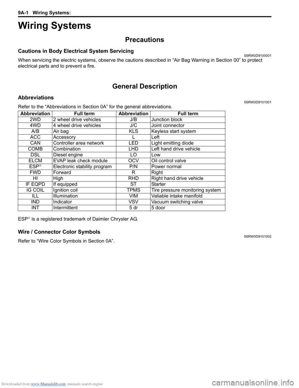
Refer to the “Abbreviations in Section 0A” for the general abbreviations.
ESP
® is a registered trademark of Daimler Chrysler AG.
Wire / Connector Color SymbolsS6RW0D9101002
Refer to “Wire Color Symbols in Section 0A”. Abbreviation Full term Abbreviation Full term
2WD 2 wheel drive vehicles J/B Junction block
4WD 4 wheel drive vehicles J/C Joint connector
A/B Air bag KLS Keyless start system
ACC Accessory L Left
CAN Controller area network LED Light emitting diode
COMB Combination LHD Left hand drive vehicle
DSL Diesel engine LO Low
ELCM EVAP leak check module OCV Oil control valve
ESP
®Electronic stability program P/N Power normal
FWD Forward R Right
HI High RHD Right hand drive vehicle
IF EQPD If equipped ST Starter
IG COIL Ignition coil TPMS Tire pressure monitoring system
ILL Illumination VIM Valiable intake manifold
IND Indicator VSV Vacuum switching valve
INT Intermittent 5 dr 5 door