2006 SUZUKI SX4 rear wheel
[x] Cancel search: rear wheelPage 642 of 1556

Downloaded from www.Manualslib.com manuals search engine 4E-37 ABS:
Front Wheel Speed Sensor Encoder On-Vehicle
Inspection
S6RW0D4506010
Before inspecting front wheel speed sensor encoder,
remove front drive shaft referring to “Front Drive Shaft
Assembly Removal and Installation in Section 3A”.
• Check sensor encoder (1) for crack, damage or
deformation.
• Turn wheel and check if sensor encoder rotation is
free from eccentricity and looseness.
• Check that no foreign material is attached.
If any faulty is found, clean or replace. Refer to “Front
Wheel Hub, Steering Knuckle and Wheel Bearing
Removal and Installation in Section 2B”.
Front Wheel Speed Sensor Encoder Removal
and Installation
S6RW0D4506011
CAUTION!
Front wheel speed sensor encoder is
included in front wheel hub assembly. If front
wheel speed sensor encoder needs to be
replaced, replace it as a front wheel hub
assembly.
For removal and installation of front wheel hub
assembly, referring to “Front Wheel Hub, Steering
Knuckle and Wheel Bearing Removal and Installation in
Section 2B”.
Rear Wheel Speed Sensor Encoder On-Vehicle
Inspection
S6RW0D4506012
For 4WD model
Refer to “Rear Wheel Speed Sensor On-Vehicle
Inspection”.
For 2WD model
Before inspecting rear wheel speed sensor encoder,
remove rear wheel speed sensor referring to “Rear
Wheel Speed Sensor Removal and Installation (2WD
Model)”.
• Check encoder (1) for crack, damage or deformation.
• Turn wheel and check if encoder rotation is free from
eccentricity and looseness.
• Check that no foreign material is attached.
If any faulty is found, clean or replace. Refer to “Rear
Wheel Hub Assembly Removal and Installation in
Section 2C”.
Rear Wheel Speed Sensor Encoder Removal
and Installation
S6RW0D4506013
CAUTION!
Rear wheel speed sensor encoder is included
in rear wheel hub assembly. If rear wheel
speed sensor encoder needs to be replaced,
replace it as a rear wheel hub assembly.
For removal and installation of front wheel hub
assembly, referring to “Rear Wheel Hub Assembly
Removal and Installation in Section 2C”.
1
I5RW0A450026-01
Page 644 of 1556

Downloaded from www.Manualslib.com manuals search engine 4E-39 ABS:
Specifications
Tightening Torque SpecificationsS6RW0D4507001
NOTE
The specified tightening torque is also described in the following.
“ABS Hydraulic Unit / Control Module Assembly Components”
Reference:
For the tightening torque of fastener not specified in this section, refer to “Fasteners Information in Section 0A”.
Special Tools and Equipment
Special ToolS6RW0D4508001
Fastening partTightening torque
Note
N⋅mkgf-mlb-ft
Brake pipe flare nut 16 1.6 11.5�)
ABS hydraulic unit / control module assembly
bolt90.9 6.5�)
ABS hydraulic unit / control module assembly
bracket bolt26 2.6 19.0�)
Front wheel speed sensor bolt 11 1.1 8.0�)
Front wheel speed sensor harness clamp bolt 11 1.1 8.0�)
Rear wheel speed sensor bolt 11 1.1 8.0�)
G sensor bolt 3.0 0.3 2.2�)
09950–78220 SUZUKI scan tool
Flare nut wrench (10 mm) —
�)This kit includes following
items. 1. Tech 2, 2. PCMCIA
card, 3. DLC cable, 4. SAE
16/19 adapter, 5. Cigarette
cable, 6. DLC loop back
adapter, 7. Battery power
cable, 8. RS232 cable, 9.
RS232 adapter, 10. RS232
loop back connector, 11.
Storage case, 12. �) / �)
Page 680 of 1556
Downloaded from www.Manualslib.com manuals search engine 5A-32 Automatic Transmission/Transaxle:
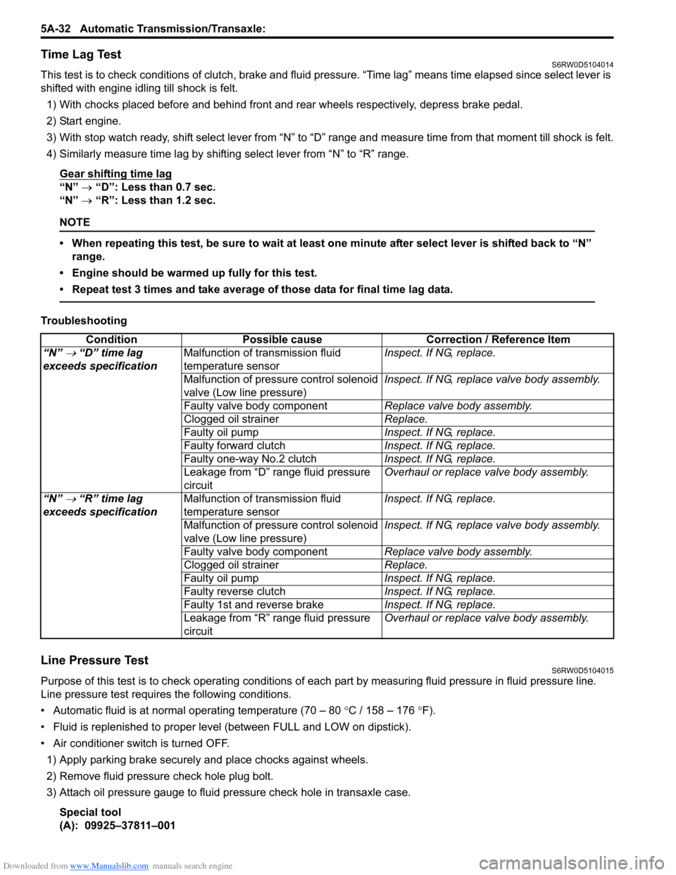
Time Lag TestS6RW0D5104014
This test is to check conditions of clutch, brake and fluid pressure. “Time lag” means time elapsed since select lever is
shifted with engine idling till shock is felt.
1) With chocks placed before and behind front and rear wheels respectively, depress brake pedal.
2) Start engine.
3) With stop watch ready, shift select lever from “N” to “D” range and measure time from that moment till shock is felt.
4) Similarly measure time lag by shifting select lever from “N” to “R” range.
Gear shifting time lag
“N” → “D”: Less than 0.7 sec.
“N” → “R”: Less than 1.2 sec.
NOTE
• When repeating this test, be sure to wait at least one minute after select lever is shifted back to “N”
range.
• Engine should be warmed up fully for this test.
• Repeat test 3 times and take average of those data for final time lag data.
Troubleshooting
Line Pressure TestS6RW0D5104015
Purpose of this test is to check operating conditions of each part by measuring fluid pressure in fluid pressure line.
Line pressure test requires the following conditions.
• Automatic fluid is at normal operating temperature (70 – 80 °C / 158 – 176 °F).
• Fluid is replenished to proper level (between FULL and LOW on dipstick).
• Air conditioner switch is turned OFF.
1) Apply parking brake securely and place chocks against wheels.
2) Remove fluid pressure check hole plug bolt.
3) Attach oil pressure gauge to fluid pressure check hole in transaxle case.
Special tool
(A): 09925–37811–001Condition Possible cause Correction / Reference Item
“N”
→ “D” time lag
exceeds specificationMalfunction of transmission fluid
temperature sensorInspect. If NG, replace.
Malfunction of pressure control solenoid
valve (Low line pressure)Inspect. If NG, replace valve body assembly.
Faulty valve body componentReplace valve body assembly.
Clogged oil strainerReplace.
Faulty oil pumpInspect. If NG, replace.
Faulty forward clutchInspect. If NG, replace.
Faulty one-way No.2 clutchInspect. If NG, replace.
Leakage from “D” range fluid pressure
circuitOverhaul or replace valve body assembly.
“N”
→ “R” time lag
exceeds specificationMalfunction of transmission fluid
temperature sensorInspect. If NG, replace.
Malfunction of pressure control solenoid
valve (Low line pressure)Inspect. If NG, replace valve body assembly.
Faulty valve body componentReplace valve body assembly.
Clogged oil strainerReplace.
Faulty oil pumpInspect. If NG, replace.
Faulty reverse clutchInspect. If NG, replace.
Faulty 1st and reverse brakeInspect. If NG, replace.
Leakage from “R” range fluid pressure
circuitOverhaul or replace valve body assembly.
Page 1115 of 1556
Downloaded from www.Manualslib.com manuals search engine Air Bag System: 8B-76
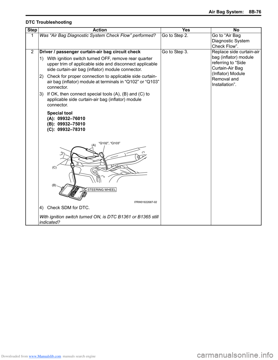
DTC Troubleshooting
Step Action Yes No
1Was “Air Bag Diagnostic System Check Flow” performed?Go to Step 2. Go to “Air Bag
Diagnostic System
Check Flow”.
2Driver / passenger curtain-air bag circuit check
1) With ignition switch turned OFF, remove rear quarter
upper trim of applicable side and disconnect applicable
side curtain-air bag (inflator) module connector.
2) Check for proper connection to applicable side curtain-
air bag (inflator) module at terminals in “Q102” or “Q103”
connector.
3) If OK, then connect special tools (A), (B) and (C) to
applicable side curtain-air bag (inflator) module
connector.
Special tool
(A): 09932–76010
(B): 09932–75010
(C): 09932–78310
4) Check SDM for DTC.
With ignition switch turned ON, is DTC B1361 or B1365 still
indicated?Go to Step 3. Replace side curtain-air
bag (inflator) module
referring to “Side
Curtain-Air Bag
(Inflator) Module
Removal and
Installation”.
STEERING WHEEL(B)(C)
(A)“Q102”, “Q103”
I7RW01822087-02
Page 1118 of 1556
Downloaded from www.Manualslib.com manuals search engine 8B-79 Air Bag System:
DTC B1362 / B1366: Curtain-Air Bag Circuit Low ResistanceS6RW0D8204063
DTC B1362: Driver Curtain-Air Bag Circuit Low Resistance
DTC B1366: Passenger Curtain-Air Bag Circuit Low Resistance
Wiring Diagram
Refer to “DTC B1361 / B1365: Curtain-Air Bag Circuit High Resistance”.
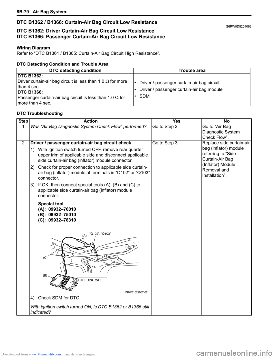
DTC Detecting Condition and Trouble Area
DTC TroubleshootingDTC detecting condition Trouble area
DTC B1362:
Driver curtain-air bag circuit is less than 1.0 Ω for more
than 4 sec.
DTC B1366:
Passenger curtain-air bag circuit is less than 1.0 Ω for
more than 4 sec.• Driver / passenger curtain-air bag circuit
• Driver / passenger curtain-air bag module
•SDM
Step Action Yes No
1Was “Air Bag Diagnostic System Check Flow” performed?Go to Step 2. Go to “Air Bag
Diagnostic System
Check Flow”.
2Driver / passenger curtain-air bag circuit check
1) With ignition switch turned OFF, remove rear quarter
upper trim of applicable side and disconnect applicable
side curtain-air bag (inflator) module connector.
2) Check for proper connection to applicable side curtain-
air bag (inflator) module at terminals in “Q102” or “Q103”
connector.
3) If OK, then connect special tools (A), (B) and (C) to
applicable side curtain-air bag (inflator) module
connector.
Special tool
(A): 09932–76010
(B): 09932–75010
(C): 09932–78310
4) Check SDM for DTC.
With ignition switch turned ON, is DTC B1362 or B1366 still
indicated?Go to Step 3. Replace side curtain-air
bag (inflator) module
referring to “Side
Curtain-Air Bag
(Inflator) Module
Removal and
Installation”.
STEERING WHEEL(B)(C)
(A)“Q102”, “Q103”
I7RW01822087-02
Page 1184 of 1556
Downloaded from www.Manualslib.com manuals search engine 9A-17 Wiring Systems:
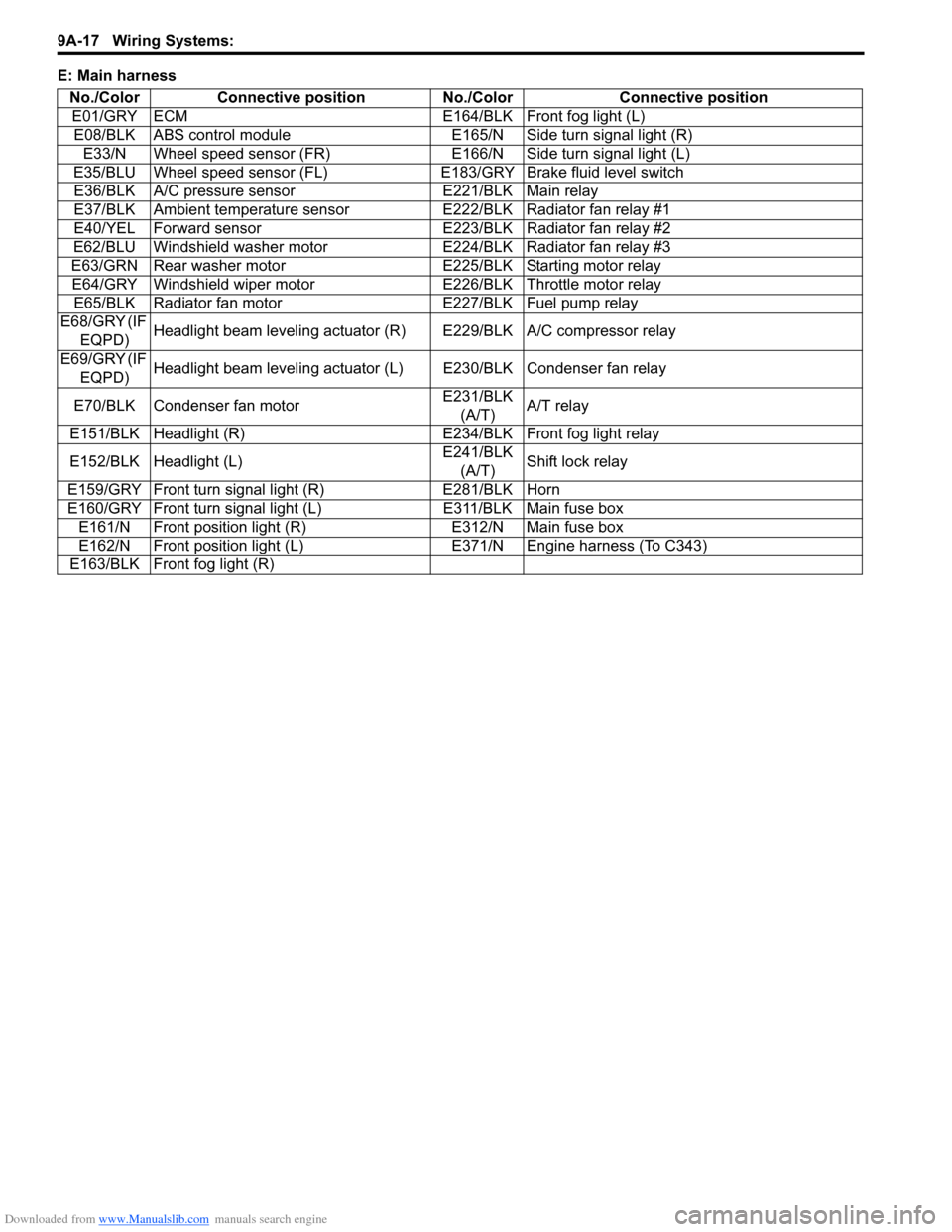
E: Main harness
No./Color Connective position No./Color Connective position
E01/GRY ECM E164/BLK Front fog light (L)
E08/BLK ABS control module E165/N Side turn signal light (R)
E33/N Wheel speed sensor (FR) E166/N Side turn signal light (L)
E35/BLU Wheel speed sensor (FL)E183/GRY Brake fluid level switch
E36/BLK A/C pressure sensor E221/BLK Main relay
E37/BLK Ambient temperature sensor E222/BLK Radiator fan relay #1
E40/YEL Forward sensor E223/BLK Radiator fan relay #2
E62/BLU Windshield washer motor E224/BLK Radiator fan relay #3
E63/GRN Rear washer motor E225/BLK Starting motor relay
E64/GRY Windshield wiper motor E226/BLK Throttle motor relay
E65/BLK Radiator fan motor E227/BLK Fuel pump relay
E68/GRY (IF
EQPD)Headlight beam leveling actuator (R) E229/BLK A/C compressor relay
E69/GRY (IF
EQPD)Headlight beam leveling actuator (L) E230/BLK Condenser fan relay
E70/BLK Condenser fan motorE231/BLK
(A/T)A/T relay
E151/BLK Headlight (R) E234/BLK Front fog light relay
E152/BLK Headlight (L)E241/BLK
(A/T)Shift lock relay
E159/GRY Front turn signal light (R) E281/BLK Horn
E160/GRY Front turn signal light (L) E311/BLK Main fuse box
E161/N Front position light (R) E312/N Main fuse box
E162/N Front position light (L) E371/N Engine harness (To C343)
E163/BLK Front fog light (R)
Page 1185 of 1556
Downloaded from www.Manualslib.com manuals search engine Wiring Systems: 9A-18
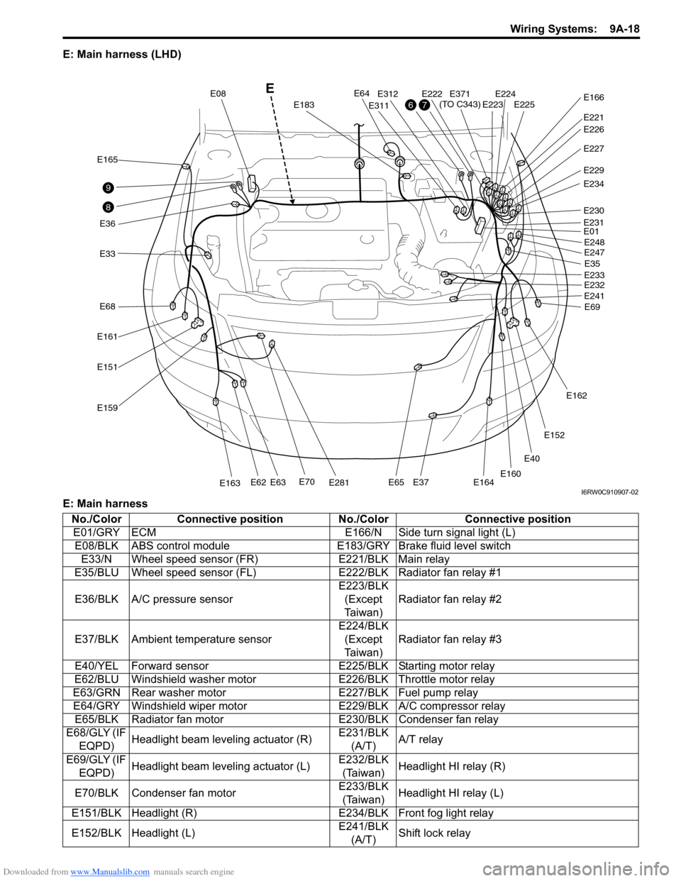
E: Main harness (LHD)
E: Main harness
E40
E33
E165
E36
E161
E68
E151
E159
E70E281E163E62E63E65E37E164
E64
E183
E08
E311
E312E222E224E225E223
E221
E371
(TO C343)E166
E227
E229
E234
E230
E01
E35
E69 E248
E247
E233
E232
E241
E162
E152
E160
E231
E226
8
9
76
E
I6RW0C910907-02
No./Color Connective position No./Color Connective position
E01/GRY ECM E166/N Side turn signal light (L)
E08/BLK ABS control module E183/GRY Brake fluid level switch
E33/N Wheel speed sensor (FR) E221/BLK Main relay
E35/BLU Wheel speed sensor (FL)E222/BLK Radiator fan relay #1
E36/BLK A/C pressure sensorE223/BLK
(Except
Ta i w a n )Radiator fan relay #2
E37/BLK Ambient temperature sensorE224/BLK
(Except
Ta i w a n )Radiator fan relay #3
E40/YEL Forward sensor E225/BLK Starting motor relay
E62/BLU Windshield washer motor E226/BLK Throttle motor relay
E63/GRN Rear washer motor E227/BLK Fuel pump relay
E64/GRY Windshield wiper motor E229/BLK A/C compressor relay
E65/BLK Radiator fan motor E230/BLK Condenser fan relay
E68/GLY (IF
EQPD)Headlight beam leveling actuator (R)E231/BLK
(A/T)A/T relay
E69/GLY (IF
EQPD)Headlight beam leveling actuator (L)E232/BLK
(Taiwan)Headlight HI relay (R)
E70/BLK Condenser fan motorE233/BLK
(Taiwan)Headlight HI relay (L)
E151/BLK Headlight (R) E234/BLK Front fog light relay
E152/BLK Headlight (L)E241/BLK
(A/T)Shift lock relay
Page 1195 of 1556
Downloaded from www.Manualslib.com manuals search engine Wiring Systems: 9A-28
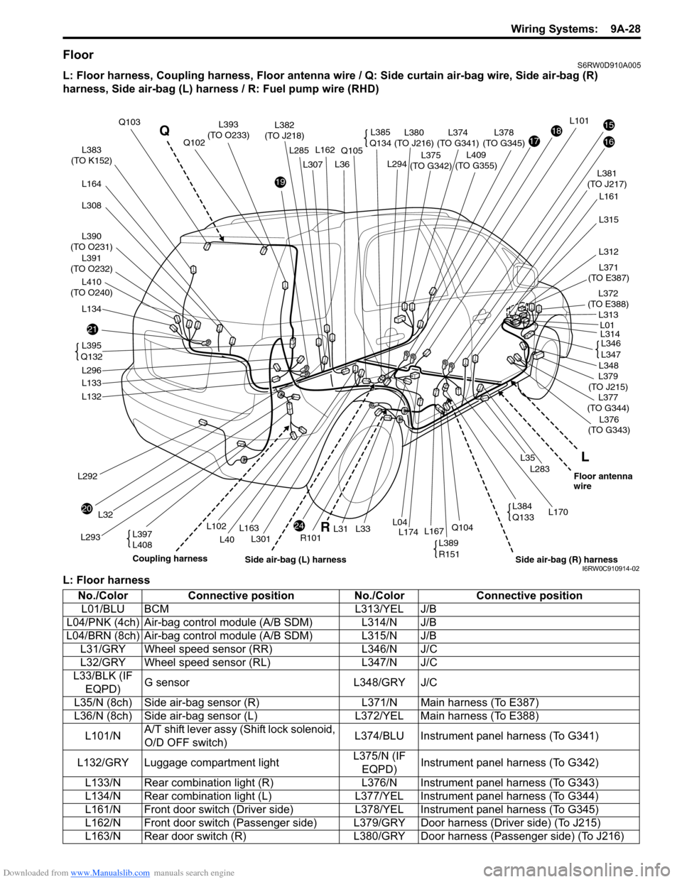
FloorS6RW0D910A005
L: Floor harness, Coupling harness, Floor antenna wire / Q: Side curtain air-bag wire, Side air-bag (R)
harness, Side air-bag (L) harness / R: Fuel pump wire (RHD)
L: Floor harness
21
20
24
19
171815
16L383
(TO K152)
L390
(TO O231)
L391
(TO O232)
L164
L134
L397
L408
L292
L293
L32
L132
L133
L296L381
(TO J217)
L375
(TO G342)
L374
(TO G341)L380
(TO J216)L378
(TO G345)
L161
L283
L35
L36
L301
Q105
R101
L102
L40
L294
L31L174L33L167Q104L04
Q103L382
(TO J218)
L376
(TO G343)
L170
L379
(TO J215)
L371
(TO E387)
L372
(TO E388)
L377
(TO G344)
Q102L162L285
L163
L101
L348
L314
L315
L312
L313
L01
L395
Q132
L385
Q134L393
(TO O233)
L346
L347
L389
R151
L384
Q133
L
R Q
Coupling harness
Side air-bag (R) harnessFloor antenna
wire
Side air-bag (L) harness
L410
(TO O240)
L308L307
L409
(TO G355)
I6RW0C910914-02
No./Color Connective position No./Color Connective position
L01/BLU BCM L313/YEL J/B
L04/PNK (4ch) Air-bag control module (A/B SDM) L314/N J/B
L04/BRN (8ch) Air-bag control module (A/B SDM) L315/N J/B
L31/GRY Wheel speed sensor (RR) L346/N J/C
L32/GRY Wheel speed sensor (RL) L347/N J/C
L33/BLK (IF
EQPD)G sensor L348/GRY J/C
L35/N (8ch) Side air-bag sensor (R) L371/N Main harness (To E387)
L36/N (8ch) Side air-bag sensor (L) L372/YEL Main harness (To E388)
L101/NA/T shift lever assy (Shift lock solenoid,
O/D OFF switch)L374/BLU Instrument panel harness (To G341)
L132/GRY Luggage compartment lightL375/N (IF
EQPD)Instrument panel harness (To G342)
L133/N Rear combination light (R) L376/N Instrument panel harness (To G343)
L134/N Rear combination light (L) L377/YEL Instrument panel harness (To G344)
L161/N Front door switch (Driver side) L378/YEL Instrument panel harness (To G345)
L162/N Front door switch (Passenger side) L379/GRY Door harness (Driver side) (To J215)
L163/N Rear door switch (R) L380/GRY Door harness (Passenger side) (To J216)