Page 1217 of 1556
Downloaded from www.Manualslib.com manuals search engine Wiring Systems: 9A-50
Junction Block Inner Circuit (Overview (Taiwan))S6RW0D910D007
Abbreviations
Abbreviation Full term Abbreviation Full term
AS Assistant (Front passenger) LP Lamp
CTR Center O/H Over head
DR Driver R/B Relay box
F-L Front L R-L Rear L
F-R Front R R-R Rear R
FR Front RR Rear
INP Instrument panel S/H Seat heater
LEV (Headlight) leveling
Page 1224 of 1556

Downloaded from www.Manualslib.com manuals search engine 9A-57 Wiring Systems:
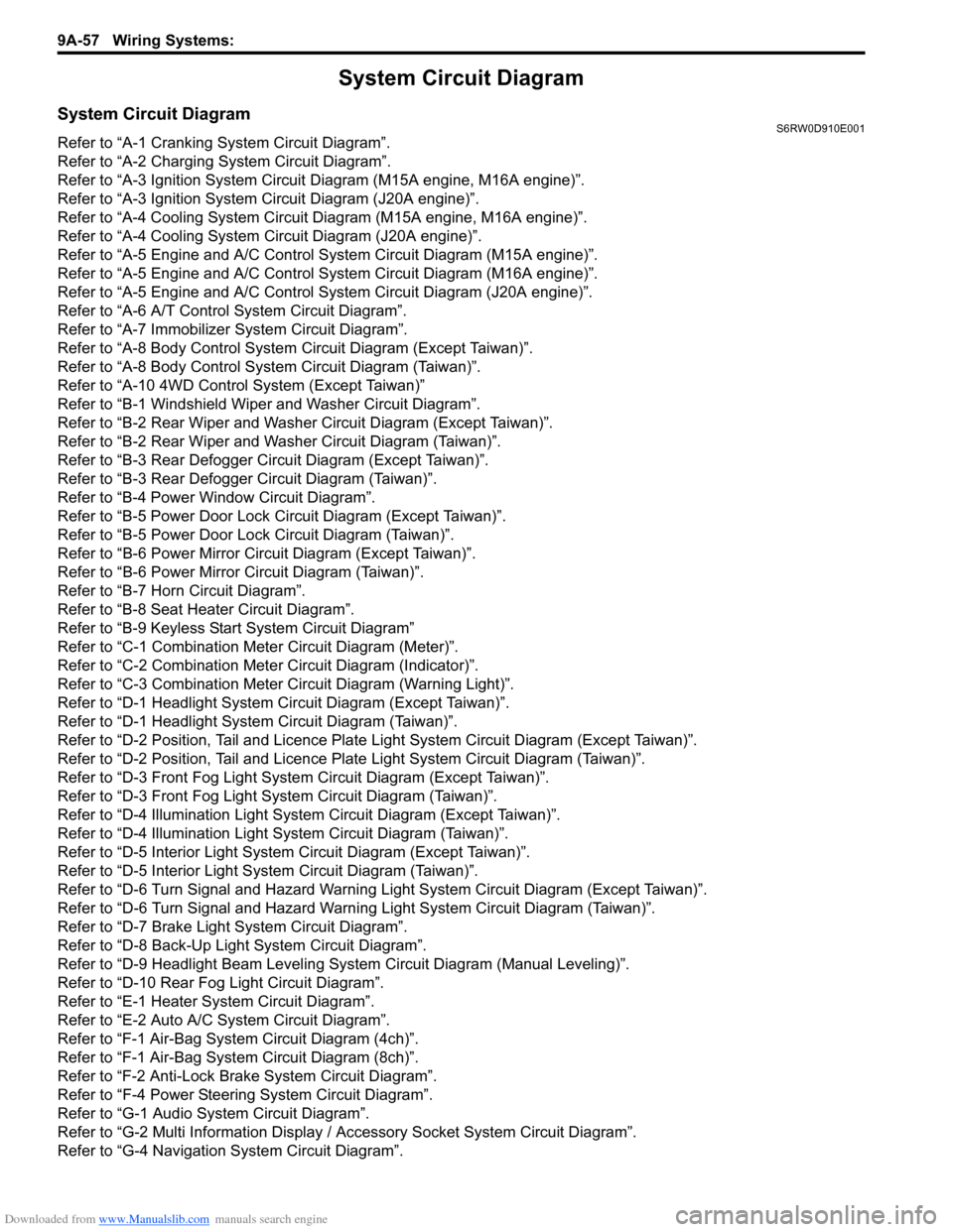
System Circuit Diagram
System Circuit DiagramS6RW0D910E001
Refer to “A-1 Cranking System Circuit Diagram”.
Refer to “A-2 Charging System Circuit Diagram”.
Refer to “A-3 Ignition System Circuit Diagram (M15A engine, M16A engine)”.
Refer to “A-3 Ignition System Circuit Diagram (J20A engine)”.
Refer to “A-4 Cooling System Circuit Diagram (M15A engine, M16A engine)”.
Refer to “A-4 Cooling System Circuit Diagram (J20A engine)”.
Refer to “A-5 Engine and A/C Control System Circuit Diagram (M15A engine)”.
Refer to “A-5 Engine and A/C Control System Circuit Diagram (M16A engine)”.
Refer to “A-5 Engine and A/C Control System Circuit Diagram (J20A engine)”.
Refer to “A-6 A/T Control System Circuit Diagram”.
Refer to “A-7 Immobilizer System Circuit Diagram”.
Refer to “A-8 Body Control System Circuit Diagram (Except Taiwan)”.
Refer to “A-8 Body Control System Circuit Diagram (Taiwan)”.
Refer to “A-10 4WD Control System (Except Taiwan)”
Refer to “B-1 Windshield Wiper and Washer Circuit Diagram”.
Refer to “B-2 Rear Wiper and Washer Circuit Diagram (Except Taiwan)”.
Refer to “B-2 Rear Wiper and Washer Circuit Diagram (Taiwan)”.
Refer to “B-3 Rear Defogger Circuit Diagram (Except Taiwan)”.
Refer to “B-3 Rear Defogger Circuit Diagram (Taiwan)”.
Refer to “B-4 Power Window Circuit Diagram”.
Refer to “B-5 Power Door Lock Circuit Diagram (Except Taiwan)”.
Refer to “B-5 Power Door Lock Circuit Diagram (Taiwan)”.
Refer to “B-6 Power Mirror Circuit Diagram (Except Taiwan)”.
Refer to “B-6 Power Mirror Circuit Diagram (Taiwan)”.
Refer to “B-7 Horn Circuit Diagram”.
Refer to “B-8 Seat Heater Circuit Diagram”.
Refer to “B-9 Keyless Start System Circuit Diagram”
Refer to “C-1 Combination Meter Circuit Diagram (Meter)”.
Refer to “C-2 Combination Meter Circuit Diagram (Indicator)”.
Refer to “C-3 Combination Meter Circuit Diagram (Warning Light)”.
Refer to “D-1 Headlight System Circuit Diagram (Except Taiwan)”.
Refer to “D-1 Headlight System Circuit Diagram (Taiwan)”.
Refer to “D-2 Position, Tail and Licence Plate Light System Circuit Diagram (Except Taiwan)”.
Refer to “D-2 Position, Tail and Licence Plate Light System Circuit Diagram (Taiwan)”.
Refer to “D-3 Front Fog Light System Circuit Diagram (Except Taiwan)”.
Refer to “D-3 Front Fog Light System Circuit Diagram (Taiwan)”.
Refer to “D-4 Illumination Light System Circuit Diagram (Except Taiwan)”.
Refer to “D-4 Illumination Light System Circuit Diagram (Taiwan)”.
Refer to “D-5 Interior Light System Circuit Diagram (Except Taiwan)”.
Refer to “D-5 Interior Light System Circuit Diagram (Taiwan)”.
Refer to “D-6 Turn Signal and Hazard Warning Light System Circuit Diagram (Except Taiwan)”.
Refer to “D-6 Turn Signal and Hazard Warning Light System Circuit Diagram (Taiwan)”.
Refer to “D-7 Brake Light System Circuit Diagram”.
Refer to “D-8 Back-Up Light System Circuit Diagram”.
Refer to “D-9 Headlight Beam Leveling System Circuit Diagram (Manual Leveling)”.
Refer to “D-10 Rear Fog Light Circuit Diagram”.
Refer to “E-1 Heater System Circuit Diagram”.
Refer to “E-2 Auto A/C System Circuit Diagram”.
Refer to “F-1 Air-Bag System Circuit Diagram (4ch)”.
Refer to “F-1 Air-Bag System Circuit Diagram (8ch)”.
Refer to “F-2 Anti-Lock Brake System Circuit Diagram”.
Refer to “F-4 Power Steering System Circuit Diagram”.
Refer to “G-1 Audio System Circuit Diagram”.
Refer to “G-2 Multi Information Display / Accessory Socket System Circuit Diagram”.
Refer to “G-4 Navigation System Circuit Diagram”.
Page 1238 of 1556
Downloaded from www.Manualslib.com manuals search engine 9A-71 Wiring Systems:
TCM
WHTRED
717C06
124C01 E01145457195526C016513
ECM
WHT
ABS
Cont.M
APP sensor Throttle position sensor
Throttle sensor
SUB
open close open close open close
open close
MAIN SUB MAIN
Throttle
motor
REDBLUGRNBRNWHTYELREDBLKWHTGRNREDYELBLU
E08
3
18
1
12E1911
6C482
156435234
RW
RW
4142405443454434365135375250E01 C01
(CAN)
(CAN)
BLKGRY
GRN/WHTGRN/YELBRN
B
P/S
Cont.M
"F-3"
RED/BLU
GWGY
IG COIL
#2 IG COIL
#1
BW
Heater fan
switch"A-3"
"E-1"
RB
"E-2"
ORNGRY/RED
GRY/REDRED/BLU
EVAP thermistor
1
3G32
8
ORN
WHT/BLKBLU/WHTORN
E382
G334
BW
Auto
Unit
A/C
pressure
sensorE36
C343
E37110
2
3
BLU/WHTORN
915
WHT/BLKBLU/WHT
Auto A/C
Manual A/C
1
8915
3
I6RW0C910944-03
Page 1269 of 1556
Downloaded from www.Manualslib.com manuals search engine Wiring Systems: 9A-102
B-8 Seat Heater Circuit DiagramS6RW0D910E060
LT GRN
LT GRNLT GRNRED/YEL
RED/YEL
RED/YEL
RED/YEL
BLUBLK
L17156
L2813 4
4
12
L1725
L2823
4
BLKGRYBLK
412
BLK
BLKBLKBLKBLK
SwitchFREE LOCK FREE LOCKSwitch
L31415
15A
S/H34J/B
6
J/C
L346C
A
L347
RY
BG
"D-4"
7
3
J/B
G272
L314
B
BLK
B
B
J/C
L348
17
BLK
21I6RW0D910913-01
Page 1273 of 1556
Downloaded from www.Manualslib.com manuals search engine Wiring Systems: 9A-106
C-3 Combination Meter Circuit Diagram (Warning Light)S6RW0D910E021
J/BMTR
10A22
31
Stepper motor and
LED output driver
Voltage regulator
Micro controller
G2716
RED/BLK
516
YB
YEL/BLK
"F-1"
CAN
High Low
WHTWHTRED
RW
10G2419
7
L01
G05
RED/BLUBRN/YEL
L1671
Parking
brake
switch
1
2
A
A
16
BLK/ORN
BLK/ORN
J/C
L348B
B
J/C
G309
Seat
belt
switch
Oil
pressure
switch
J/B
13
Y
YEL
"D-4"
ILL cancel
switch
E371
C3437
G343
L37693G333
E38156
GRY
GRY
1C162
RED/BLK
RED/BLUBRN/YELGRYRED/BLK
E1831
Brake
fluid
level
switch
2
71114
BLK
BLK
BLK
9
BLKBLK
W
WHTRED
1
2
A
AB
B
J/C
G311
RBGBYRB
BCM
"A-10"
4WD
Cont.M
Interface circuit
RED
6
R"A-10"
4WD
Cont.M
(CAN) (CAN) (CAN)
IF EQPD
Except Taiwan
Taiwan
Without seat heater
With seat heater A
A
B
L170
L281C
D
G04
G05A
BE04
G05A
B
BCD
B
6
8AB14
40AB11
9AB5
7AB2
3AB4
1AB
I6RW0D910915-01
Page 1294 of 1556
Downloaded from www.Manualslib.com manuals search engine 9A-127 Wiring Systems:
E-1 Heater System Circuit DiagramS6RW0D910E030
BRN
GRN/WHT
10ABACK
21
M
BLK/RED
J/B J/B
BLK/ORN
G309
J/C
G62
Fresh / Recircle
actuator
61
4
GRNRED
9
G1547
8
G306
J/C
4
G272
BCM
"A-8"GW
BCM
"B-3"GY
GRN/YEL
8
RED/YEL
RED/YELRED/BLK
RED/BLKRED/BLK
101314 5 6
REAR
DEFREO
FRE A/CHARF REO
CIRCUIT
Mode control
switch
13
AAD
DB
B
B
1
RY"D-4""B-3"BR
J/B
B
BLK
11
B
BLK/YELRED/BLUBLK/ORN
3
BLK
14
J/C
G306A
A
BLKBLK/YEL
J/C
G306C
C
Except Taiwan
Taiwan A
B
RY"D-4"
AB
BA
I6RW0C910996-03
Page 1295 of 1556
Downloaded from www.Manualslib.com manuals search engine Wiring Systems: 9A-128
RED
M
BLU/WHTYEL
BLK/WHTBLK/WHTBLU/WHTBLU/WHT
BLK/WHT
G1555
BRN
J/B
BLK/YEL
2
1G61
11
G65
Fan driver
4 2
1 3
Blower
fan
motor
G2736
1 327
6
FAN
Heater fan switch
42 5
1
3
30ABLW
6
10A
35IG2
SIG
Blower
fan
relay
E323
7
G2729
G309
J/C
1114
B
B
BLK
BLKBLK
BLK
BLU
1
Individual circuit
fuse box (No.1)
ECM
"A-5"BW
I6RW0C910997-02
Page 1370 of 1556

Downloaded from www.Manualslib.com manuals search engine 9C-18 Instrumentation / Driver Info. / Horn:
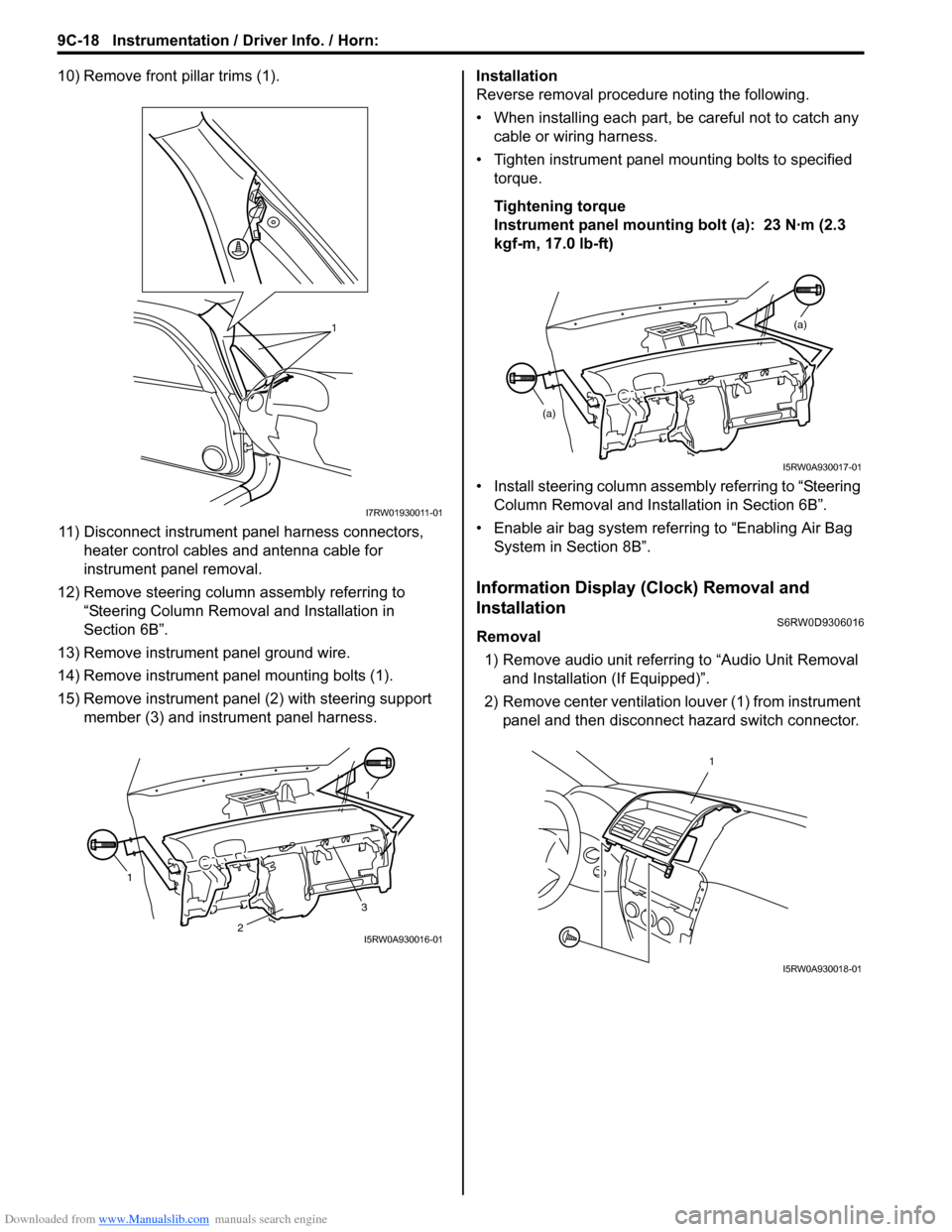
10) Remove front pillar trims (1).
11) Disconnect instrument panel harness connectors,
heater control cables and antenna cable for
instrument panel removal.
12) Remove steering column assembly referring to
“Steering Column Removal and Installation in
Section 6B”.
13) Remove instrument panel ground wire.
14) Remove instrument panel mounting bolts (1).
15) Remove instrument panel (2) with steering support
member (3) and instrument panel harness.Installation
Reverse removal procedure noting the following.
• When installing each part, be careful not to catch any
cable or wiring harness.
• Tighten instrument panel mounting bolts to specified
torque.
Tightening torque
Instrument panel mounting bolt (a): 23 N·m (2.3
kgf-m, 17.0 lb-ft)
• Install steering column assembly referring to “Steering
Column Removal and Installation in Section 6B”.
• Enable air bag system referring to “Enabling Air Bag
System in Section 8B”.
Information Display (Clock) Removal and
Installation
S6RW0D9306016
Removal
1) Remove audio unit referring to “Audio Unit Removal
and Installation (If Equipped)”.
2) Remove center ventilation louver (1) from instrument
panel and then disconnect hazard switch connector.
1
I7RW01930011-01
11
3
2I5RW0A930016-01
(a)
(a)
I5RW0A930017-01
1
I5RW0A930018-01