2006 SUZUKI SX4 lighting systems
[x] Cancel search: lighting systemsPage 5 of 1556

Downloaded from www.Manualslib.com manuals search engine 00
0
1
2
3
4
5
6
7
8
9
10
11
Vo l u m e 1
Precautions............................................................... 00-i
Precautions ............................................................ 00-1
General Information ................................................... 0-i
General Information ............................................... 0A-1
Maintenance and Lubrication ................................. 0B-1
Engine ......................................................................... 1-i
Precautions .............................................................. 1-1
Engine General Information and Diagnosis ........... 1A-1
Aux. Emission Control Devices .............................. 1B-1
Engine Electrical Devices....................................... 1C-1
Engine Mechanical ................................................. 1D-1
Engine Lubrication System .................................... 1E-1
Engine Cooling System .......................................... 1F-1
Fuel System ...........................................................1G-1
Ignition System....................................................... 1H-1
Starting System ....................................................... 1I-1
Charging System.....................................................1J-1
Exhaust System ..................................................... 1K-1
Suspension ................................................................. 2-i
Precautions .............................................................. 2-1
Suspension General Diagnosis .............................. 2A-1
Front Suspension ................................................... 2B-1
Rear Suspension.................................................... 2C-1
Wheels and Tires ................................................... 2D-1
Driveline / Axle ........................................................... 3-i
Precautions .............................................................. 3-1
Drive Shaft / Axle ................................................... 3A-1
Differential .............................................................. 3B-1
Transfer .................................................................. 3C-1
Propeller Shafts...................................................... 3D-1
Brakes ......................................................................... 4-i
Precautions .............................................................. 4-1
Brake Control System and Diagnosis .................... 4A-1
Front Brakes........................................................... 4B-1
Rear Brakes ........................................................... 4C-1
Parking Brake......................................................... 4D-1
ABS ........................................................................ 4E-1
Transmission / Transaxle .......................................... 5-i
Precautions .............................................................. 5-1
Automatic Transmission/Transaxle ........................ 5A-1
Manual Transmission/Transaxle ............................ 5B-1
Clutch ..................................................................... 5C-1
Vo l u m e 2
Precautions ............................................................... 00-i
Precautions ............................................................ 00-1
Steering ....................................................................... 6-i
Precautions .............................................................. 6-1
Steering General Diagnosis ................................... 6A-1
Steering Wheel and Column .................................. 6B-1
Power Assisted Steering System ...........................6C-1
HVAC ........................................................................... 7-i
Precautions .............................................................. 7-1
Heater and Ventilation............................................ 7A-1
Air Conditioning System ......................................... 7B-1
Restraint ...................................................................... 8-i
Precautions .............................................................. 8-1
Seat Belts ............................................................... 8A-1
Air Bag System ...................................................... 8B-1
Body, Cab and Accessories ...................................... 9-i
Precautions .............................................................. 9-1
Wiring Systems ...................................................... 9A-1
Lighting Systems .................................................... 9B-1
Instrumentation / Driver Info. / Horn .......................9C-1
Wipers / Washers ...................................................9D-1
Glass / Windows / Mirrors ...................................... 9E-1
Security and Locks ................................................. 9F-1
Seats ..................................................................... 9G-1
Interior Trim ............................................................9H-1
Hood / Fenders / Doors .......................................... 9J-1
Body Structure ....................................................... 9K-1
Paint / Coatings ...................................................... 9L-1
Exterior Trim .......................................................... 9M-1
Control Systems ....................................................... 10-i
Precautions ............................................................ 10-1
Body Electrical Control System ............................ 10B-1
Immobilizer Control System .................................10C-1
Keyless Start System ........................................... 10E-1
TABLE OF CONTENTS
Page 1162 of 1556
Downloaded from www.Manualslib.com manuals search engine 9-ii Table of Contents
B-9 Keyless Start System Circuit Diagram...... 9A-103
C-1 Combination Meter Circuit Diagram
(Meter) .......................................................... 9A-104
C-2 Combination Meter Circuit Diagram
(Indicator) ...................................................... 9A-105
C-3 Combination Meter Circuit Diagram
(Warning Light) ............................................. 9A-106
D-1 Headlight System Circuit Diagram
(Except Taiwan) ............................................ 9A-108
D-1 Headlight System Circuit Diagram
(Taiwan) ........................................................ 9A-110
D-2 Position, Tail and Licence Plate Light
System Circuit Diagram (Except Taiwan) ..... 9A-111
D-2 Position, Tail and Licence Plate Light
System Circuit Diagram (Taiwan) ................. 9A-112
D-3 Front Fog Light System Circuit Diagram
(Except Taiwan) ............................................ 9A-113
D-3 Front Fog Light System Circuit Diagram
(Taiwan) ........................................................ 9A-114
D-4 Illumination Light System Circuit Diagram
(Except Taiwan) ............................................ 9A-115
D-4 Illumination Light System Circuit Diagram
(Taiwan) ........................................................ 9A-116
D-5 Interior Light System Circuit Diagram
(Except Taiwan) ............................................ 9A-117
D-5 Interior Light System Circuit Diagram
(Taiwan) ........................................................ 9A-118
D-6 Turn Signal and Hazard Warning Light
System Circuit Diagram (Except Taiwan) ..... 9A-119
D-6 Turn Signal and Hazard Warning Light
System Circuit Diagram (Taiwan) ................. 9A-121
D-7 Brake Light System Circuit Diagram ........ 9A-123
D-8 Back-Up Light System Circuit Diagram .... 9A-124
D-9 Headlight Beam Leveling System Circuit
Diagram (Manual Leveling)........................... 9A-125
D-10 Rear Fog Light Circuit Diagram .............. 9A-126
E-1 Heater System Circuit Diagram ................ 9A-127
E-2 Auto A/C System Circuit Diagram ............ 9A-129
F-1 Air-Bag System Circuit Diagram (4ch) ...... 9A-131
F-1 Air-Bag System Circuit Diagram (8ch) ...... 9A-132
F-2 Anti-Lock Brake System Circuit Diagram.. 9A-134
F-4 Power Steering System Circuit Diagram .. 9A-136
G-1 Audio System Circuit Diagram ................. 9A-138
G-2 Multi Information Display / Accessory
Socket System Circuit Diagram .................... 9A-140
G-4 Navigation System Circuit Diagram ......... 9A-141
List of Connector .............................................9A-143
List of Connectors ........................................... 9A-143
C Connector .................................................... 9A-143
E Connector .................................................... 9A-145
G Connector .................................................... 9A-146
J Connector ..................................................... 9A-149
K Connector .................................................... 9A-149
L Connector..................................................... 9A-150
O Connector .................................................... 9A-152
Q Connector (8ch)........................................... 9A-152
R Connector .................................................... 9A-152
S Connector .................................................... 9A-152
Lighting Systems .................................... 9B-1
Precautions ...........................................................9B-1
Precautions for Discharge Headlight Service
(If Equipped)...................................................... 9B-1
Precautions in Diagnosing Troubles
(Headlight Auto Leveling System) ..................... 9B-1
General Description .............................................9B-1
Discharge Headlight Description (If
Equipped) .......................................................... 9B-1
Headlight Auto Leveling System Description
(If Equipped)...................................................... 9B-2
Auto-On Headlight System Description (If
Equipped) .......................................................... 9B-4
Schematic and Routing Diagram ........................9B-5
Headlight Auto Leveling System Wiring
Circuit Diagram ................................................. 9B-5
Component Location ...........................................9B-6
Lighting System Components Location............... 9B-6
Interior Light System Location............................. 9B-7
Diagnostic Information and Procedures ............9B-7
Self-Diagnosis Function for Headlight Auto
Leveling System ................................................ 9B-7
Headlight Leveling Warning Light Check ............ 9B-8
Headlight Symptom Diagnosis (Discharge
Headlight Model) ............................................... 9B-8
Headlight Symptom diagnosis (Other than
Discharge Headlight Model) .............................. 9B-9
Auto-On Headlight System Symptom
Diagnosis (If Equipped) ..................................... 9B-9
DRL System Symptom Diagnosis (If
Equipped) ........................................................ 9B-10
Headlight Auto Leveling System Symptom
Diagnosis (If Equipped) ................................... 9B-10
Headlight Manual Leveling System Symptom
Diagnosis (If Equipped) ................................... 9B-10
Turn Signal and Hazard Warning Light
Symptom Diagnosis ........................................ 9B-11
Clearance, Tail and License Plate Light
Symptom Diagnosis ........................................ 9B-11
Back-Up Light Symptom Diagnosis................... 9B-12
Brake Light Symptom Diagnosis ....................... 9B-12
Front Fog Light Symptom Diagnosis (If
Equipped) ........................................................ 9B-12
Rear Fog Light Symptom Diagnosis (If
Equipped) ........................................................ 9B-12
Illumination Cancel System Symptom
Diagnosis (If Equipped) ................................... 9B-13
Interior Light Symptom Diagnosis ..................... 9B-13
DRL Operation Inspection (If Equipped) ........... 9B-13
Inspection of DRL Controller and Its Circuits
(If Equipped).................................................... 9B-13
Auto-On Headlight Operation Inspection (If
Equipped) ........................................................ 9B-15
Inspection of Auto-On Headlight Controller
and Its Circuit (If Equipped)............................. 9B-15
Inspection of Headlight Leveling Control
Module and Its Circuit (Headlight Auto
Leveling System)............................................. 9B-16
Repair Instructions ............................................9B-18
Headlight Housing Removal and Installation .... 9B-18
Page 1170 of 1556
Downloaded from www.Manualslib.com manuals search engine 9A-3 Wiring Systems:
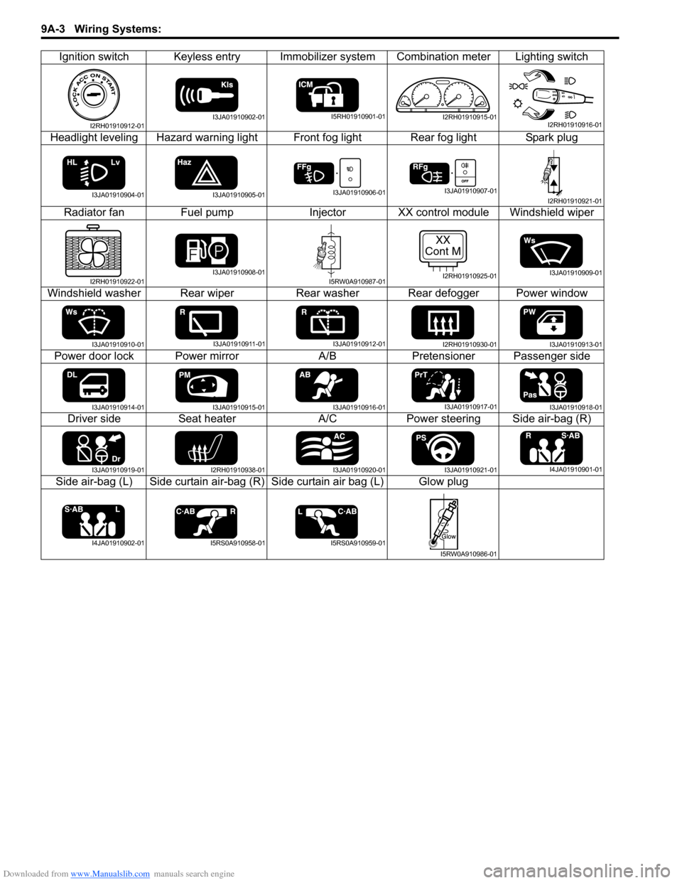
Ignition switch Keyless entry Immobilizer system Combination meter Lighting switch
Headlight leveling Hazard warning light Front fog light Rear fog light Spark plug
Radiator fan Fuel pump Injector XX control module Windshield wiper
Windshield washer Rear wiper Rear washer Rear defogger Power window
Power door lock Power mirror A/B Pretensioner Passenger side
Driver side Seat heater A/C Power steering Side air-bag (R)
Side air-bag (L) Side curtain air-bag (R) Side curtain air bag (L) Glow plug
I2RH01910912-01I3JA01910902-01I5RH01910901-01I2RH01910915-01I2RH01910916-01
I3JA01910904-01I3JA01910905-01I3JA01910906-01I3JA01910907-01I2RH01910921-01
I2RH01910922-01I3JA01910908-01I5RW0A910987-01
XX
Cont M
I2RH01910925-01I3JA01910909-01
I3JA01910910-01I3JA01910911-01I3JA01910912-01I2RH01910930-01I3JA01910913-01
I3JA01910914-01I3JA01910915-01I3JA01910916-01I3JA01910917-01I3JA01910918-01
I3JA01910919-01I2RH01910938-01I3JA01910920-01I3JA01910921-01I4JA01910901-01
I4JA01910902-01I5RS0A910958-01I5RS0A910959-01
I5RW0A910986-01
Page 1320 of 1556
Downloaded from www.Manualslib.com manuals search engine 9B-1 Lighting Systems:
Body, Cab and Accessories
Lighting Systems
Precautions
Precautions for Discharge Headlight Service (If Equipped)S6RW0D9200001
WARNING!
• Do not touch igniter or ballast when lighting switch is at “HEAD” position to avoid possible electric
shock.
• Do not measure voltage or resistance with tester connected to output connector of ballast or igniter
to avoid possible electric shock.
• Do not perform work where exposed to water including rain or with wet hands to avoid possible
electric shock.
• Disassembling igniter or ballast is strictly prohibited as it may cause an electric shock.
• Before inspecting or repairing discharge headlight or its peripheral parts, make sure that lighting
switch is at OFF position and battery is disconnected at negative terminal to avoid possible
electrical shock.
• Do not set lighting switch to “HEAD” position with connector disconnected or any part removed to
avoid possible electric shock.
• Do not touch glass surface of headlight bulb. Oil or grease attached on it may not only make bulb
service life shorter but also cause bulb to burst when lighting switch is turned on.
• Mercury, metal iodide and xenon gas are sealed in discharge headlight bulb. Be sure to dispose of
used discharge headlight bulb properly according to applicable rules or regulations.
Precautions in Diagnosing Troubles (Headlight Auto Leveling System)S6RW0D9200002
• Be sure to read “Air Bag Warning in Section 00” before inspection and observe what is written there.
• Replacement of height sensor and headlight leveling control module. When height sensor and/or headlight leveling
control module is replaced with new one, perform initialization of headlight auto leveling system according to
“Initialization of Headlight Auto Leveling System”.
General Description
Discharge Headlight Description (If Equipped)S6RW0D9201001
Discharge headlight provides more brightness and consumes less electricity as compared with the conventional
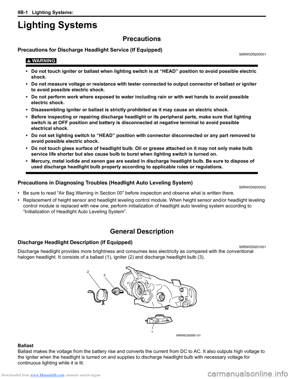
halogen headlight. It consists of a ballast (1), igniter (2) and discharge headlight bulb (3).
Ballast
Ballast makes the voltage from the battery rise and converts the current from DC to AC. It also outputs high voltage to
the igniter when the headlight is turned on and supplies to discharge headlight bulb with necessary voltage for
continuous lighting while it is lit.
2
1 3
I6RW0C920001-01
Page 1321 of 1556
Downloaded from www.Manualslib.com manuals search engine Lighting Systems: 9B-2
Igniter
Igniter generates high voltage needed to turn on the discharge headlight. It is charged with high voltage raised by the
ballast and it applies voltage pulse as high as about 20,000V to the tungsten electrode in the discharge headlight bulb.
After the discharge headlights light up, the ballast supplies voltage to bulbs.
Discharge headlight bulb
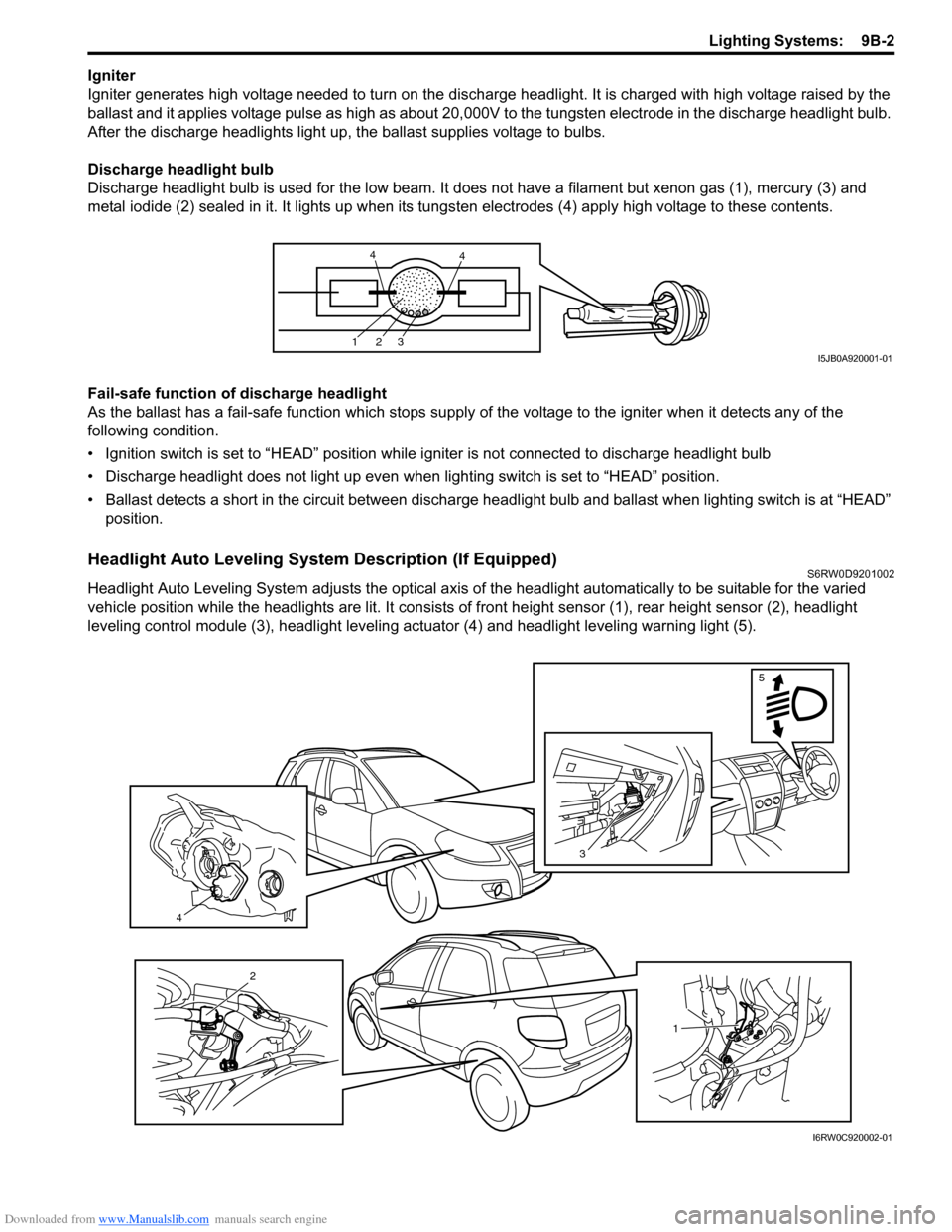
Discharge headlight bulb is used for the low beam. It does not have a filament but xenon gas (1), mercury (3) and
metal iodide (2) sealed in it. It lights up when its tungsten electrodes (4) apply high voltage to these contents.
Fail-safe function of discharge headlight
As the ballast has a fail-safe function which stops supply of the voltage to the igniter when it detects any of the
following condition.
• Ignition switch is set to “HEAD” position while igniter is not connected to discharge headlight bulb
• Discharge headlight does not light up even when lighting switch is set to “HEAD” position.
• Ballast detects a short in the circuit between discharge headlight bulb and ballast when lighting switch is at “HEAD”
position.
Headlight Auto Leveling System Description (If Equipped)S6RW0D9201002
Headlight Auto Leveling System adjusts the optical axis of the headlight automatically to be suitable for the varied
vehicle position while the headlights are lit. It consists of front height sensor (1), rear height sensor (2), headlight
leveling control module (3), headlight leveling actuator (4) and headlight leveling warning light (5).
123
44
I5JB0A920001-01
4
3
5
1
2
I6RW0C920002-01
Page 1322 of 1556
Downloaded from www.Manualslib.com manuals search engine 9B-3 Lighting Systems:
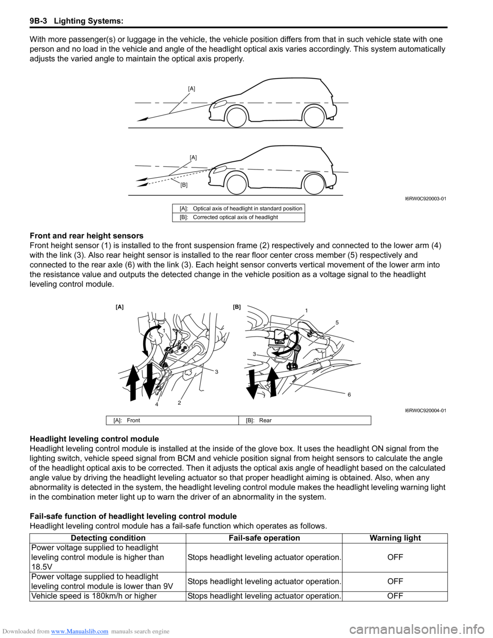
With more passenger(s) or luggage in the vehicle, the vehicle position differs from that in such vehicle state with one
person and no load in the vehicle and angle of the headlight optical axis varies accordingly. This system automatically
adjusts the varied angle to maintain the optical axis properly.
Front and rear height sensors
Front height sensor (1) is installed to the front suspension frame (2) respectively and connected to the lower arm (4)
with the link (3). Also rear height sensor is installed to the rear floor center cross member (5) respectively and
connected to the rear axle (6) with the link (3). Each height sensor converts vertical movement of the lower arm into
the resistance value and outputs the detected change in the vehicle position as a voltage signal to the headlight
leveling control module.
Headlight leveling control module
Headlight leveling control module is installed at the inside of the glove box. It uses the headlight ON signal from the
lighting switch, vehicle speed signal from BCM and vehicle position signal from height sensors to calculate the angle
of the headlight optical axis to be corrected. Then it adjusts the optical axis angle of headlight based on the calculated
angle value by driving the headlight leveling actuator so that proper headlight aiming is obtained. Also, when any
abnormality is detected in the system, the headlight leveling control module makes the headlight leveling warning light
in the combination meter light up to warn the driver of an abnormality in the system.
Fail-safe function of headlight leveling control module
Headlight leveling control module has a fail-safe function which operates as follows.
[A]
[A]
[B]
I6RW0C920003-01
[A]: Optical axis of headlight in standard position
[B]: Corrected optical axis of headlight
1
5
[A] [B]
6
3
1
2
3
4I6RW0C920004-01
[A]: Front [B]: Rear
Detecting condition Fail-safe operation Warning light
Power voltage supplied to headlight
leveling control module is higher than
18.5VStops headlight leveling actuator operation. OFF
Power voltage supplied to headlight
leveling control module is lower than 9VStops headlight leveling actuator operation. OFF
Vehicle speed is 180km/h or higher Stops headlight leveling actuator operation. OFF
Page 1323 of 1556
Downloaded from www.Manualslib.com manuals search engine Lighting Systems: 9B-4
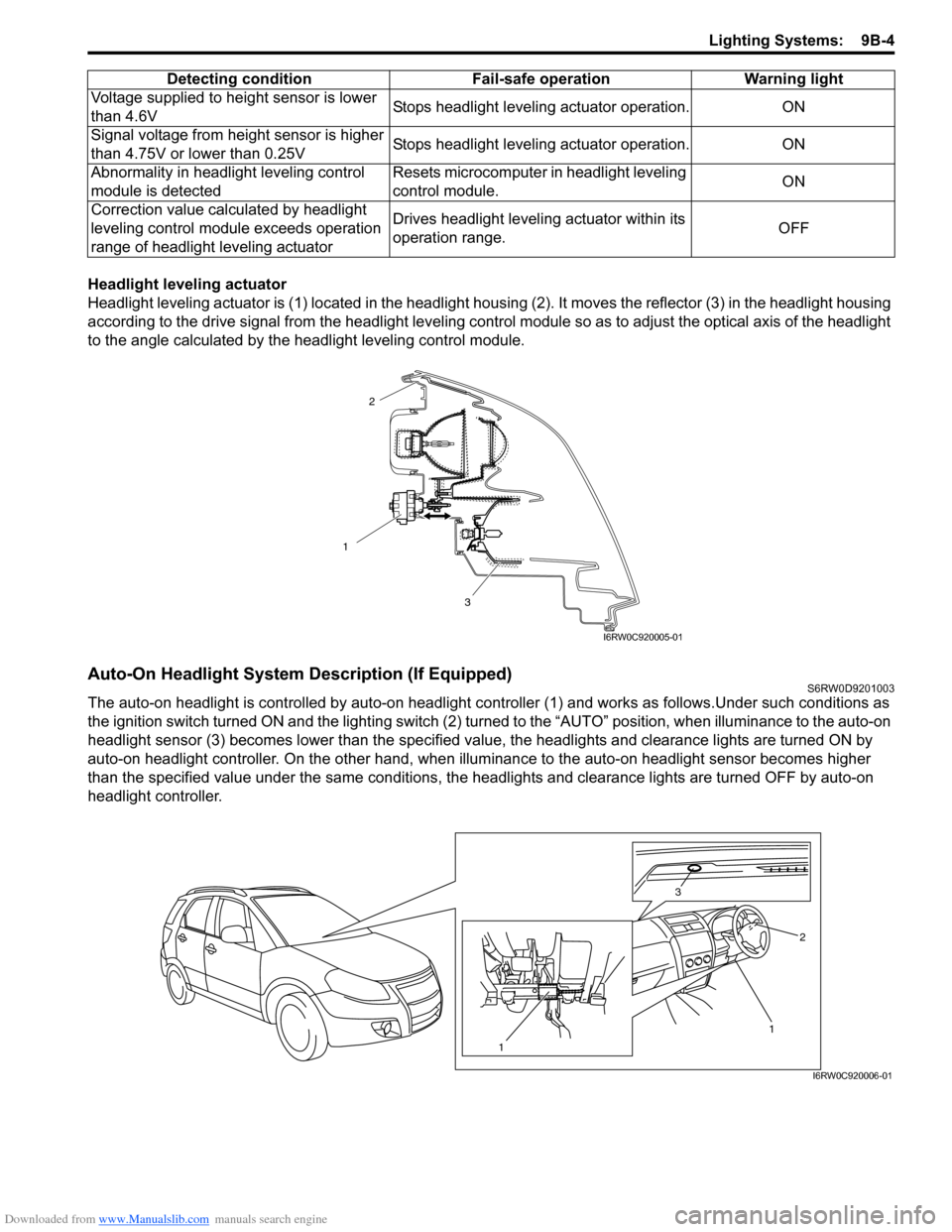
Headlight leveling actuator
Headlight leveling actuator is (1) located in the headlight housing (2). It moves the reflector (3) in the headlight housing
according to the drive signal from the headlight leveling control module so as to adjust the optical axis of the headlight
to the angle calculated by the headlight leveling control module.
Auto-On Headlight System Description (If Equipped)S6RW0D9201003
The auto-on headlight is controlled by auto-on headlight controller (1) and works as follows.Under such conditions as
the ignition switch turned ON and the lighting switch (2) turned to the “AUTO” position, when illuminance to the auto-on
headlight sensor (3) becomes lower than the specified value, the headlights and clearance lights are turned ON by
auto-on headlight controller. On the other hand, when illuminance to the auto-on headlight sensor becomes higher
than the specified value under the same conditions, the headlights and clearance lights are turned OFF by auto-on
headlight controller.Voltage supplied to height sensor is lower
than 4.6VStops headlight leveling actuator operation. ON
Signal voltage from height sensor is higher
than 4.75V or lower than 0.25VStops headlight leveling actuator operation. ON
Abnormality in headlight leveling control
module is detectedResets microcomputer in headlight leveling
control module.ON
Correction value calculated by headlight
leveling control module exceeds operation
range of headlight leveling actuatorDrives headlight leveling actuator within its
operation range.OFF Detecting condition Fail-safe operation Warning light
1
3
2
I6RW0C920005-01
1 3
2
1
I6RW0C920006-01
Page 1324 of 1556
Downloaded from www.Manualslib.com manuals search engine 9B-5 Lighting Systems:
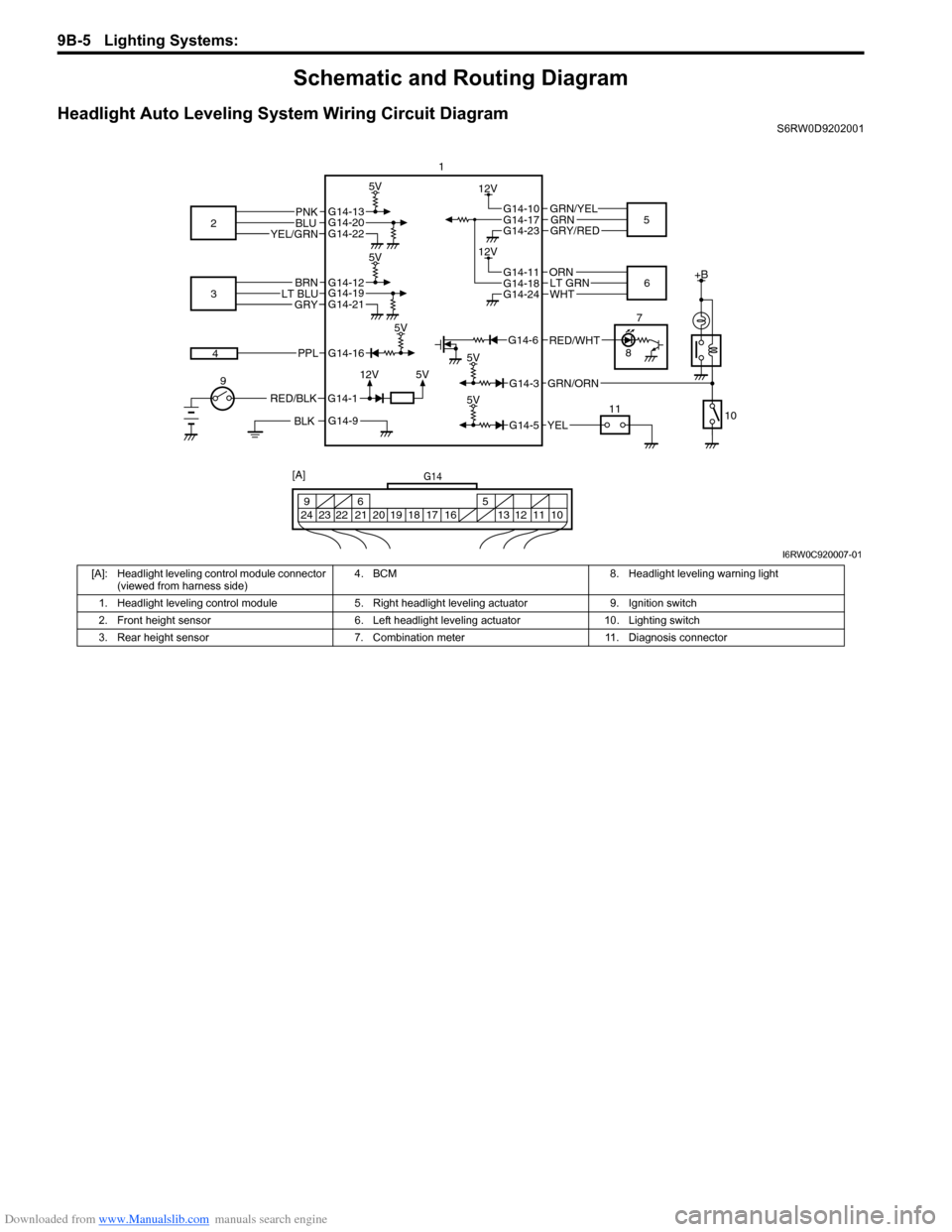
Schematic and Routing Diagram
Headlight Auto Leveling System Wiring Circuit DiagramS6RW0D9202001
G14-12G14-19G14-21
G14-10
G14-23
+B
5V
5V
GRN/YEL
GRY/RED
BLK
G14-112V
BRNLT BLUGRY
RED/BLK
3
G14-13G14-20G14-22
5V
PNKBLUYEL/GRN2
45
9
10 11 1
5V
5V
12V
G14-16
G14-3
PPL
GRN/ORN
5V
G14-5YEL
G14-17GRN
G14-11
G14-24
ORN
WHT6 12VG14-18LT GRN
7
8
G14-6
G14-9
RED/WHT
G14
10 11 12 13 16 17 18 19 205 6 9
21 22 23 24
[A]
I6RW0C920007-01
[A]: Headlight leveling control module connector
(viewed from harness side)4. BCM 8. Headlight leveling warning light
1. Headlight leveling control module 5. Right headlight leveling actuator 9. Ignition switch
2. Front height sensor 6. Left headlight leveling actuator 10. Lighting switch
3. Rear height sensor 7. Combination meter 11. Diagnosis connector