Page 1900 of 2896
CYLINDER BLOCK
EM-91
C
D
E
F
G
H
I
J
K
L
MA
EM
Revision: June 20062007 Versa
HOW TO SELECT MAIN BEARING
When New Cylinder Block and Crankshaft are Used
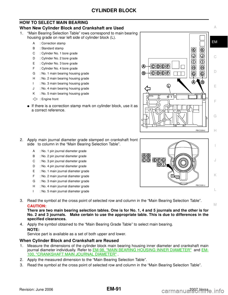
1. “Main Bearing Selection Table” rows correspond to main bearing
housing grade on rear left side of cylinder block (L).
�If there is a correction stamp mark on cylinder block, use it as
a correct reference.
2. Apply main journal diameter grade stamped on crankshaft front
side to column in the “Main Bearing Selection Table”.
3. Read the symbol at the cross point of selected row and column in the “Main Bearing Selection Table”.
CAUTION:
There are two main bearing selection tables. One is for No. 1, 4 and 5 journals and the other is for
No. 2 and 3 journals. Make certain to use the appropriate table. This is due to differences in the
specified clearances.
4. Apply the symbol obtained to the “Main Bearing Grade Table” to select main bearing.
NOTE:
Service part is available as a set of both upper and lower.
When Cylinder Block and Crankshaft are Reused
1. Measure the dimensions of the cylinder block main bearing housing inner diameter and crankshaft main
journal diameter individually. Refer to EM-98, "
MAIN BEARING HOUSING INNER DIAMETER" and EM-
100, "CRANKSHAFT MAIN JOURNAL DIAMETER" .
2. Apply the measured dimension to the “Main Bearing Selection Table”.
3. Read the symbol at the cross point of selected row and column in the “Main Bearing Selection Table”.
A : Correction stamp
B : Standard stamp
C : Cylinder No. 1 bore grade
D : Cylinder No. 2 bore grade
E : Cylinder No. 3 bore grade
F : Cylinder No. 4 bore grade
G : No. 1 main bearing housing grade
H : No. 2 main bearing housing grade
I : No. 3 main bearing housing grade
J : No. 4 main bearing housing grade
K : No. 5 main bearing housing grade
: Engine front
PBIC3264J
A : No. 1 pin journal diameter grade
B : No. 2 pin journal diameter grade
C : No. 3 pin journal diameter grade
D : No. 4 pin journal diameter grade
E : No. 1 main journal diameter grade
F : No. 2 main journal diameter grade
G : No. 3 main journal diameter grade
H : No. 4 main journal diameter grade
I : No. 5 main journal diameter grade
PBIC3261J
Page 1901 of 2896
EM-92Revision: June 2006
CYLINDER BLOCK
2007 Versa
CAUTION:
There are two main bearing selection tables. One is for No. 1, 4 and 5 journals and the other is for
No. 2 and 3 journals. Make certain to use the appropriate table. This is due to differences in the
specified clearances.
4. Apply the symbol obtained to the “Main Bearing Grade Table” to select main bearing.
NOTE:
Service part is available as a set of both upper and lower.
Main Bearing Selection Table (No. 1, 4 and 5 journals)
PBIC4078E
Page 1905 of 2896
EM-96Revision: June 2006
CYLINDER BLOCK
2007 Versa
�When replacing piston and piston pin assembly, refer to EM-99, "Piston to Cylinder Bore Clearance" .
NOTE:
�Piston is available together with piston pin as assembly.
�Piston pin (piston pin hole) grade is provided only for the parts installed at the plant. For service parts,
no grades can be selected. (Only grade “0” is available.)
PISTON RING SIDE CLEARANCE
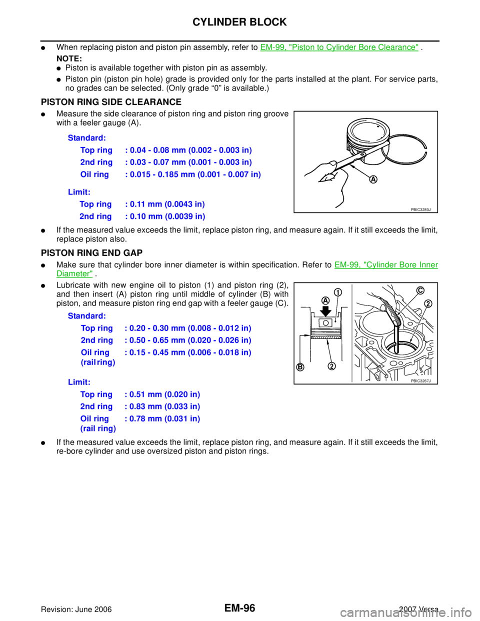
�Measure the side clearance of piston ring and piston ring groove
with a feeler gauge (A).
�If the measured value exceeds the limit, replace piston ring, and measure again. If it still exceeds the limit,
replace piston also.
PISTON RING END GAP
�Make sure that cylinder bore inner diameter is within specification. Refer to EM-99, "Cylinder Bore Inner
Diameter" .
�Lubricate with new engine oil to piston (1) and piston ring (2),
and then insert (A) piston ring until middle of cylinder (B) with
piston, and measure piston ring end gap with a feeler gauge (C).
�If the measured value exceeds the limit, replace piston ring, and measure again. If it still exceeds the limit,
re-bore cylinder and use oversized piston and piston rings.Standard:
Top ring : 0.04 - 0.08 mm (0.002 - 0.003 in)
2nd ring : 0.03 - 0.07 mm (0.001 - 0.003 in)
Oil ring : 0.015 - 0.185 mm (0.001 - 0.007 in)
Limit:
Top ring : 0.11 mm (0.0043 in)
2nd ring : 0.10 mm (0.0039 in)
PBIC3280J
Standard:
Top ring : 0.20 - 0.30 mm (0.008 - 0.012 in)
2nd ring : 0.50 - 0.65 mm (0.020 - 0.026 in)
Oil ring
(rail ring) : 0.15 - 0.45 mm (0.006 - 0.018 in)
Limit:
Top ring : 0.51 mm (0.020 in)
2nd ring : 0.83 mm (0.033 in)
Oil ring
(rail ring): 0.78 mm (0.031 in)
PBIC3267J
Page 1914 of 2896
SERVICE DATA AND SPECIFICATIONS (SDS)
EM-105
C
D
E
F
G
H
I
J
K
L
MA
EM
Revision: June 20062007 Versa
SERVICE DATA AND SPECIFICATIONS (SDS)PFP:00030
Standard and LimitEBS00U80
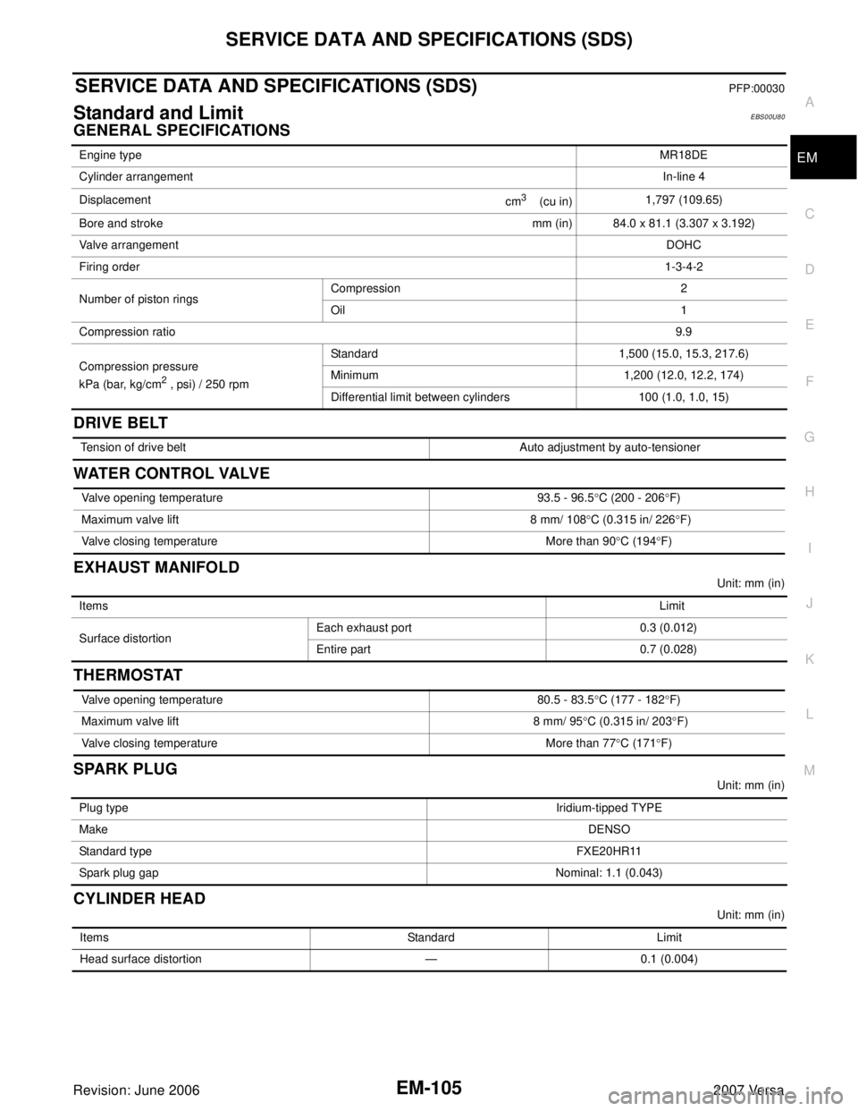
GENERAL SPECIFICATIONS
DRIVE BELT
WATER CONTROL VALVE
EXHAUST MANIFOLD
Unit: mm (in)
THERMOSTAT
SPARK PLUG
Unit: mm (in)
CYLINDER HEAD
Unit: mm (in) Engine typeMR18DE
Cylinder arrangementIn-line 4
Displacement
cm
3 (cu in)1,797 (109.65)
Bore and stroke mm (in) 84.0 x 81.1 (3.307 x 3.192)
Valve arrangementDOHC
Firing order1-3-4-2
Number of piston ringsCompression 2
Oil 1
Compression ratio9.9
Compression pressure
kPa (bar, kg/cm
2 , psi) / 250 rpmStandard 1,500 (15.0, 15.3, 217.6)
Minimum 1,200 (12.0, 12.2, 174)
Differential limit between cylinders 100 (1.0, 1.0, 15)
Tension of drive belt Auto adjustment by auto-tensioner
Valve opening temperature 93.5 - 96.5°C (200 - 206°F)
Maximum valve lift 8 mm/ 108°C (0.315 in/ 226°F)
Valve closing temperature More than 90°C (194°F)
Items Limit
Surface distortionEach exhaust port 0.3 (0.012)
Entire part 0.7 (0.028)
Valve opening temperature 80.5 - 83.5°C (177 - 182°F)
Maximum valve lift 8 mm/ 95°C (0.315 in/ 203°F)
Valve closing temperature More than 77°C (171°F)
Plug typeIridium-tipped TYPE
MakeDENSO
Standard typeFXE20HR11
Spark plug gapNominal: 1.1 (0.043)
Items Standard Limit
Head surface distortion — 0.1 (0.004)
Page 1915 of 2896
EM-106Revision: June 2006
SERVICE DATA AND SPECIFICATIONS (SDS)
2007 Versa
VA LV E
Va lv e Tim in g
Unit: degree
( ): Valve timing control “ON”
Valve Dimensions
Unit: mm (in) Normal cylinder head height “H” 130.9 (5.15) — Items Standard Limit
PBIC0924E
Va l v e t i m i n g
ab c de f
212 224 -8 (32) 52 (12) 7 25
PBIC4542E
Valve head diameter “D”Intake 33.8 - 34.1 (1.331 - 1.343)
Exhaust 27.6 - 27.9 (1.087 - 1.098)
Valve length “L”Intake 106.21 (4.181)
Exhaust 105.26 (4.144)
Valve stem diameter “d”Intake 5.465 - 5.480 (0.2152 - 0.2157)
Exhaust 5.455 - 5.470 (0.2148 - 0.2154)
Valve seat angle “α”45°15′ - 45°45′
Valve margin “T”Intake 1.1 (0.043)
Exhaust 1.2 (0.047)
SEM 18 8A
Page 1916 of 2896
SERVICE DATA AND SPECIFICATIONS (SDS)
EM-107
C
D
E
F
G
H
I
J
K
L
MA
EM
Revision: June 20062007 Versa
Valve Clearance
Unit: mm (in)
*: Approximately 80°C (176°F)
Available Valve Lifter
Items Cold Hot* (reference data)
Intake 0.26 - 0.34 (0.010 - 0.013) 0.304 - 0.416 (0.012 - 0.016)
Exhaust 0.29 - 0.37 (0.011 - 0.015) 0.308 - 0.432 (0.012 - 0.017)
Thickness mm (in) Identification mark
3.00 (0.1181) 300
3.02 (0.1189) 302
3.04 (0.1197) 304
3.06 (0.1205) 306
3.08 (0.1213) 308
3.10 (0.1220) 310
3.12 (0.1228) 312
3.14 (0.1236) 314
3.16 (0.1244) 316
3.18 (0.1252) 318
3.20 (0.1260) 320
3.22 (0.1268) 322
3.24 (0.1276) 324
3.26 (0.1283) 326
3.28 (0.1291) 328
3.30 (0.1299) 330
3.32 (0.1307) 332
3.34 (0.1315) 334
3.36 (0.1323) 336
3.38 (0.1331) 338
3.40 (0.1339) 340
3.42 (0.1346) 342
3.44 (0.1354) 344
3.46 (0.1362) 346
3.48 (0.1370) 348
3.50 (0.1378) 350
KBIA0 119 E
Page 1917 of 2896
EM-108Revision: June 2006
SERVICE DATA AND SPECIFICATIONS (SDS)
2007 Versa
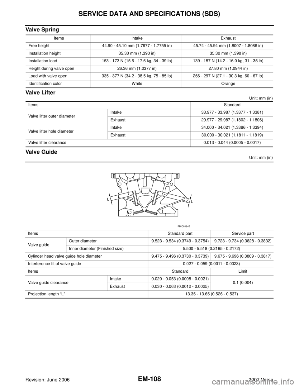
Va lv e S p ri n g
Valve Lifter
Unit: mm (in)
Valve Guide
Unit: mm (in) Items Intake Exhaust
Free height 44.90 - 45.10 mm (1.7677 - 1.7755 in) 45.74 - 45.94 mm (1.8007 - 1.8086 in)
Installation height 35.30 mm (1.390 in) 35.30 mm (1.390 in)
Installation load 153 - 173 N (15.6 - 17.6 kg, 34 - 39 lb) 139 - 157 N (14.2 - 16.0 kg, 31 - 35 lb)
Height during valve open 26.36 mm (1.0377 in) 27.80 mm (1.0944 in)
Load with valve open 335 - 377 N (34.2 - 38.5 kg, 75 - 85 lb) 266 - 297 N (27.1 - 30.3 kg, 60 - 67 lb)
Identification color White Orange
ItemsStandard
Valve lifter outer diameterIntake 33.977 - 33.987 (1.3377 - 1.3381)
Exhaust 29.977 - 29.987 (1.1802 - 1.1806)
Valve lifter hole diameterIntake 34.000 - 34.021 (1.3386 - 1.3394)
Exhaust 30.000 - 30.021 (1.1811 - 1.1819)
Valve lifter clearance0.013 - 0.044 (0.0005 - 0.0017)
Items Standard part Service part
Valve guideOuter diameter 9.523 - 9.534 (0.3749 - 0.3754) 9.723 - 9.734 (0.3828 - 0.3832)
Inner diameter (Finished size) 5.500 - 5.518 (0.2165 - 0.2172)
Cylinder head valve guide hole diameter 9.475 - 9.496 (0.3730 - 0.3739) 9.675 - 9.696 (0.3809 - 0.3817)
Interference fit of valve guide 0.027 - 0.059 (0.0011 - 0.0023)
ItemsStandard Limit
Valve guide clearanceIntake 0.020 - 0.053 (0.0008 - 0.0021)
0.1 (0.004)
Exhaust 0.030 - 0.063 (0.0012 - 0.0025)
Projection length “L” 13.35 - 13.65 (0.526 - 0.537)
PBIC0184E
Page 1918 of 2896
SERVICE DATA AND SPECIFICATIONS (SDS)
EM-109
C
D
E
F
G
H
I
J
K
L
MA
EM
Revision: June 20062007 Versa
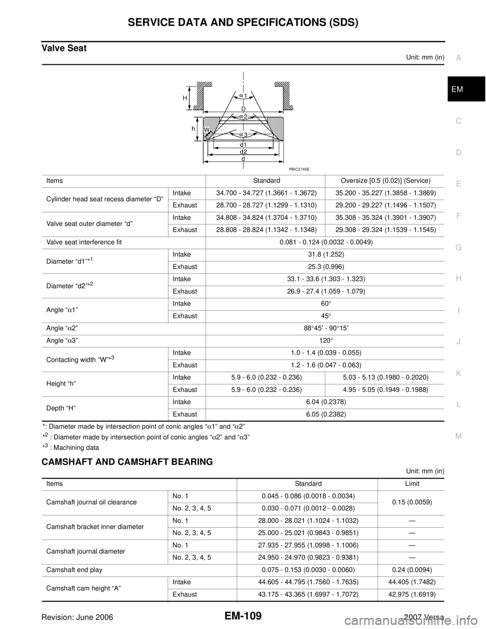
Valve Seat
Unit: mm (in)
*: Diameter made by intersection point of conic angles “α1” and “α2”
*
2 : Diameter made by intersection point of conic angles “α2” and “α3”
*3 : Machining data
CAMSHAFT AND CAMSHAFT BEARING
Unit: mm (in) Items Standard Oversize [0.5 (0.02)] (Service)
Cylinder head seat recess diameter “D”Intake 34.700 - 34.727 (1.3661 - 1.3672) 35.200 - 35.227 (1.3858 - 1.3869)
Exhaust 28.700 - 28.727 (1.1299 - 1.1310) 29.200 - 29.227 (1.1496 - 1.1507)
Valve seat outer diameter “d”Intake 34.808 - 34.824 (1.3704 - 1.3710) 35.308 - 35.324 (1.3901 - 1.3907)
Exhaust 28.808 - 28.824 (1.1342 - 1.1348) 29.308 - 29.324 (1.1539 - 1.1545)
Valve seat interference fit 0.081 - 0.124 (0.0032 - 0.0049)
Diameter “d1”*
1Intake 31.8 (1.252)
Exhaust 25.3 (0.996)
Diameter “d2”*
2Intake 33.1 - 33.6 (1.303 - 1.323)
Exhaust 26.9 - 27.4 (1.059 - 1.079)
Angle “α1”Intake 60°
Exhaust 45°
Angle “α2”88°45′ - 90°15′
Angle “α3”120°
Contacting width “W”*
3Intake 1.0 - 1.4 (0.039 - 0.055)
Exhaust 1.2 - 1.6 (0.047 - 0.063)
Height “h”Intake 5.9 - 6.0 (0.232 - 0.236) 5.03 - 5.13 (0.1980 - 0.2020)
Exhaust 5.9 - 6.0 (0.232 - 0.236) 4.95 - 5.05 (0.1949 - 0.1988)
Depth “H”Intake 6.04 (0.2378)
Exhaust 6.05 (0.2382)
PBIC2745E
ItemsStandard Limit
Camshaft journal oil clearanceNo. 1 0.045 - 0.086 (0.0018 - 0.0034)
0.15 (0.0059)
No. 2, 3, 4, 5 0.030 - 0.071 (0.0012 - 0.0028)
Camshaft bracket inner diameterNo. 1 28.000 - 28.021 (1.1024 - 1.1032) —
No. 2, 3, 4, 5 25.000 - 25.021 (0.9843 - 0.9851) —
Camshaft journal diameterNo. 1 27.935 - 27.955 (1.0998 - 1.1006) —
No. 2, 3, 4, 5 24.950 - 24.970 (0.9823 - 0.9381) —
Camshaft end play 0.075 - 0.153 (0.0030 - 0.0060) 0.24 (0.0094)
Camshaft cam height “A”Intake 44.605 - 44.795 (1.7560 - 1.7635) 44.405 (1.7482)
Exhaust 43.175 - 43.365 (1.6997 - 1.7072) 42.975 (1.6919)