Page 1978 of 2896
PRECAUTIONS
GI-7
C
D
E
F
G
H
I
J
K
L
MB
GI
Revision: June 20062007 Versa
HOSE CLAMPING
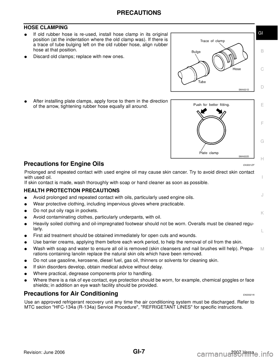
�If old rubber hose is re-used, install hose clamp in its original
position (at the indentation where the old clamp was). If there is
a trace of tube bulging left on the old rubber hose, align rubber
hose at that position.
�Discard old clamps; replace with new ones.
�After installing plate clamps, apply force to them in the direction
of the arrow, tightening rubber hose equally all around.
Precautions for Engine OilsEAS001ZF
Prolonged and repeated contact with used engine oil may cause skin cancer. Try to avoid direct skin contact
with used oil.
If skin contact is made, wash thoroughly with soap or hand cleaner as soon as possible.
HEALTH PROTECTION PRECAUTIONS
�Avoid prolonged and repeated contact with oils, particularly used engine oils.
�Wear protective clothing, including impervious gloves where practicable.
�Do not put oily rags in pockets.
�Avoid contaminating clothes, particularly underpants, with oil.
�Heavily soiled clothing and oil-impregnated footwear should not be worn. Overalls must be cleaned regu-
larly.
�First aid treatment should be obtained immediately for open cuts and wounds.
�Use barrier creams, applying them before each work period, to help the removal of oil from the skin.
�Wash with soap and water to ensure all oil is removed (skin cleansers and nail brushes will help). Prepa-
rations containing lanolin replace the natural skin oils which have been removed.
�Do not use gasoline, kerosene, diesel fuel, gas oil, thinners or solvents for cleaning skin.
�If skin disorders develop, obtain medical advice without delay.
�Where practical, degrease components prior to handling.
�Where there is a risk of eye contact, eye protection should be worn, for example, chemical goggles or face
shields; in addition an eye wash facility should be provided.
Precautions for Air ConditioningEAS0021N
Use an approved refrigerant recovery unit any time the air conditioning system must be discharged. Refer to
MTC section "HFC-134a (R-134a) Service Procedure", "REFRIGETANT LINES" for specific instructions.
SM A02 1D
SM A02 2D
Page 1980 of 2896
HOW TO USE THIS MANUAL
GI-9
C
D
E
F
G
H
I
J
K
L
MB
GI
Revision: June 20062007 Versa
Relation between Illustrations and DescriptionsEAS001ZL
The following sample explains the ralationship between the part description in an illustration, the part name in
the text and the service procedures.
SAIA0519E
Page 1981 of 2896
GI-10
HOW TO USE THIS MANUAL
Revision: June 20062007 Versa
ComponentsEAS001ZM
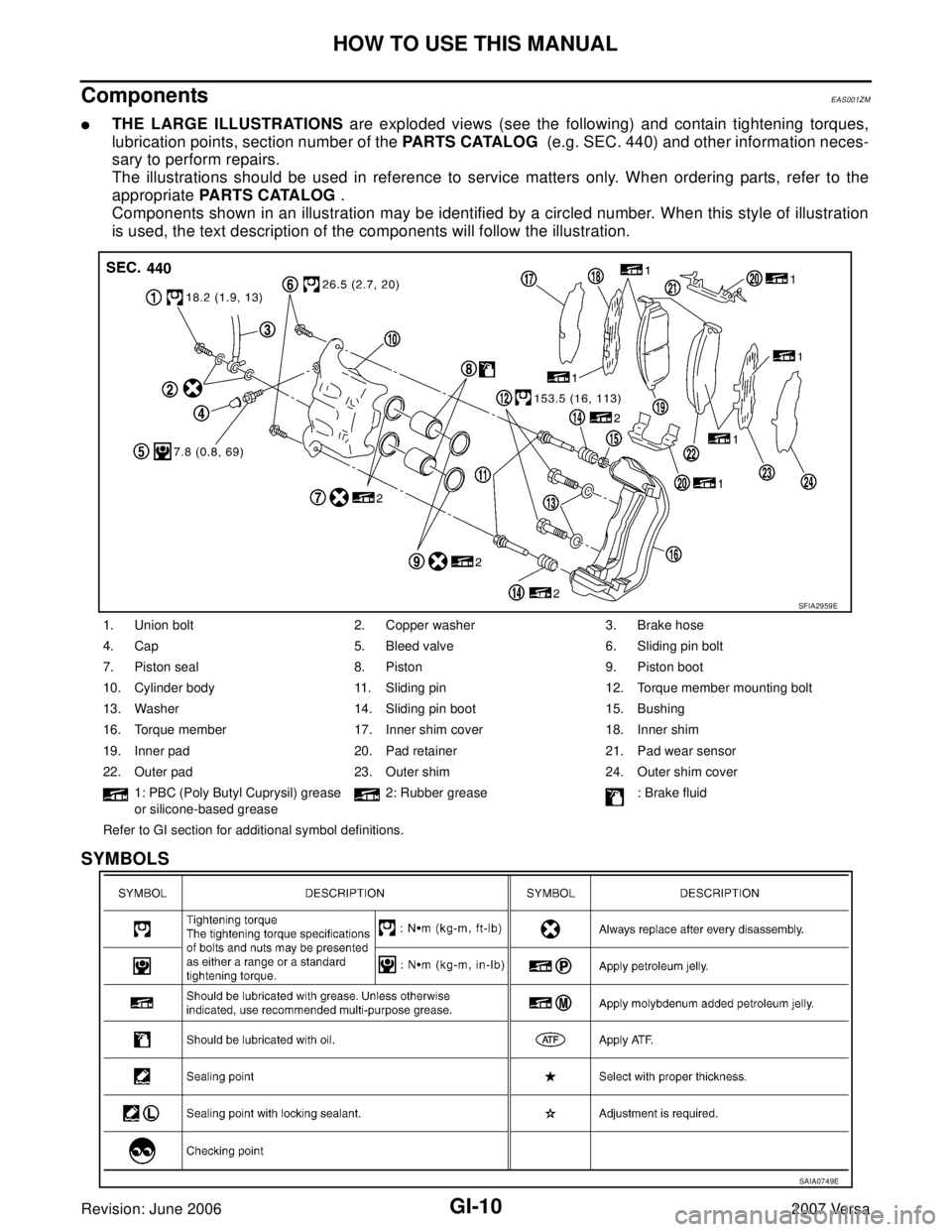
�THE LARGE ILLUSTRATIONS are exploded views (see the following) and contain tightening torques,
lubrication points, section number of the PA R T S C ATA L O G (e.g. SEC. 440) and other information neces-
sary to perform repairs.
The illustrations should be used in reference to service matters only. When ordering parts, refer to the
appropriate PA R T S C ATA L O G .
Components shown in an illustration may be identified by a circled number. When this style of illustration
is used, the text description of the components will follow the illustration.
SYMBOLS
1. Union bolt 2. Copper washer 3. Brake hose
4. Cap 5. Bleed valve 6. Sliding pin bolt
7. Piston seal 8. Piston 9. Piston boot
10. Cylinder body 11. Sliding pin 12. Torque member mounting bolt
13. Washer 14. Sliding pin boot 15. Bushing
16. Torque member 17. Inner shim cover 18. Inner shim
19. Inner pad 20. Pad retainer 21. Pad wear sensor
22. Outer pad 23. Outer shim 24. Outer shim cover
1: PBC (Poly Butyl Cuprysil) grease
or silicone-based grease2: Rubber grease : Brake fluid
Refer to GI section for additional symbol definitions.
SFIA2959E
SAIA0749E
Page 1994 of 2896
HOW TO USE THIS MANUAL
GI-23
C
D
E
F
G
H
I
J
K
L
MB
GI
Revision: June 20062007 Versa
AbbreviationsEAS0021P
The following ABBREVIATIONS are used:
ABBREVIATION DESCRIPTION
A/C Air Conditioner
A/T Automatic Transaxle/Transmission
ATF Automatic Transmission Fluid
CVT Continuously Variable Transmission
D
1Drive range 1st gear
D
2Drive range 2nd gear
D
3Drive range 3rd gear
D
4Drive range 4th gear
FR, RR Front, Rear
LH, RH Left-Hand, Right-Hand
M/T Manual Transaxle/Transmission
OD Overdrive
P/S Power Steering
SAE Society of Automotive Engineers, Inc.
SDS Service Data and Specifications
SST Special Service Tools
2WD 2-Wheel Drive
2
22nd range 2nd gear
2
12nd range 1st gear
1
21st range 2nd gear
1
11st range 1st gear
Page 1995 of 2896
GI-24
SERVICE INFORMATION FOR ELECTRICAL INCIDENT
Revision: June 20062007 Versa
SERVICE INFORMATION FOR ELECTRICAL INCIDENTPFP:00000
How to Check Terminal EAS0023R
CONNECTOR AND TERMINAL PIN KIT
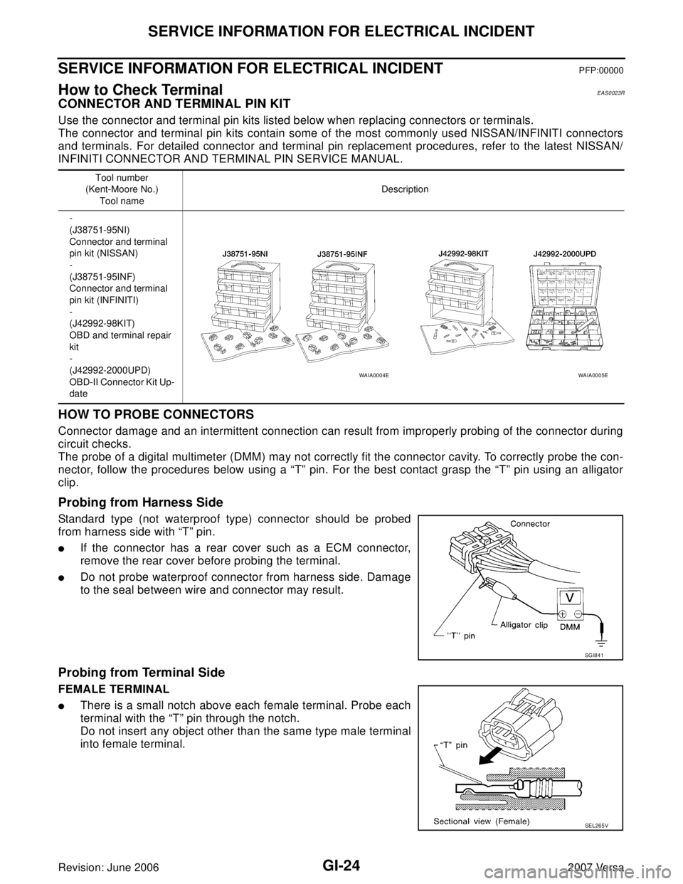
Use the connector and terminal pin kits listed below when replacing connectors or terminals.
The connector and terminal pin kits contain some of the most commonly used NISSAN/INFINITI connectors
and terminals. For detailed connector and terminal pin replacement procedures, refer to the latest NISSAN/
INFINITI CONNECTOR AND TERMINAL PIN SERVICE MANUAL.
HOW TO PROBE CONNECTORS
Connector damage and an intermittent connection can result from improperly probing of the connector during
circuit checks.
The probe of a digital multimeter (DMM) may not correctly fit the connector cavity. To correctly probe the con-
nector, follow the procedures below using a “T” pin. For the best contact grasp the “T” pin using an alligator
clip.
Probing from Harness Side
Standard type (not waterproof type) connector should be probed
from harness side with “T” pin.
�If the connector has a rear cover such as a ECM connector,
remove the rear cover before probing the terminal.
�Do not probe waterproof connector from harness side. Damage
to the seal between wire and connector may result.
Probing from Terminal Side
FEMALE TERMINAL
�There is a small notch above each female terminal. Probe each
terminal with the “T” pin through the notch.
Do not insert any object other than the same type male terminal
into female terminal.
Tool number
(Kent-Moore No.)
Tool nameDescription
-
(J38751-95NI)
Connector and terminal
pin kit (NISSAN)
-
(J38751-95INF)
Connector and terminal
pin kit (INFINITI)
-
(J42992-98KIT)
OBD and terminal repair
kit
-
(J42992-2000UPD)
OBD-II Connector Kit Up-
date
WAIA0004EWAIA0005E
SGI841
SEL265V
Page 1996 of 2896
SERVICE INFORMATION FOR ELECTRICAL INCIDENT
GI-25
C
D
E
F
G
H
I
J
K
L
MB
GI
Revision: June 20062007 Versa
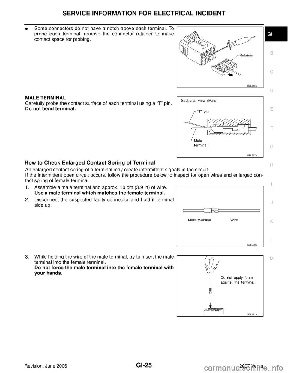
�Some connectors do not have a notch above each terminal. To
probe each terminal, remove the connector retainer to make
contact space for probing.
MALE TERMINAL
Carefully probe the contact surface of each terminal using a “T” pin.
Do not bend terminal.
How to Check Enlarged Contact Spring of Terminal
An enlarged contact spring of a terminal may create intermittent signals in the circuit.
If the intermittent open circuit occurs, follow the procedure below to inspect for open wires and enlarged con-
tact spring of female terminal.
1. Assemble a male terminal and approx. 10 cm (3.9 in) of wire.
Use a male terminal which matches the female terminal.
2. Disconnect the suspected faulty connector and hold it terminal
side up.
3. While holding the wire of the male terminal, try to insert the male
terminal into the female terminal.
Do not force the male terminal into the female terminal with
your hands.
SEL266V
SEL267V
SEL270V
SEL271V
Page 1997 of 2896
GI-26
SERVICE INFORMATION FOR ELECTRICAL INCIDENT
Revision: June 20062007 Versa
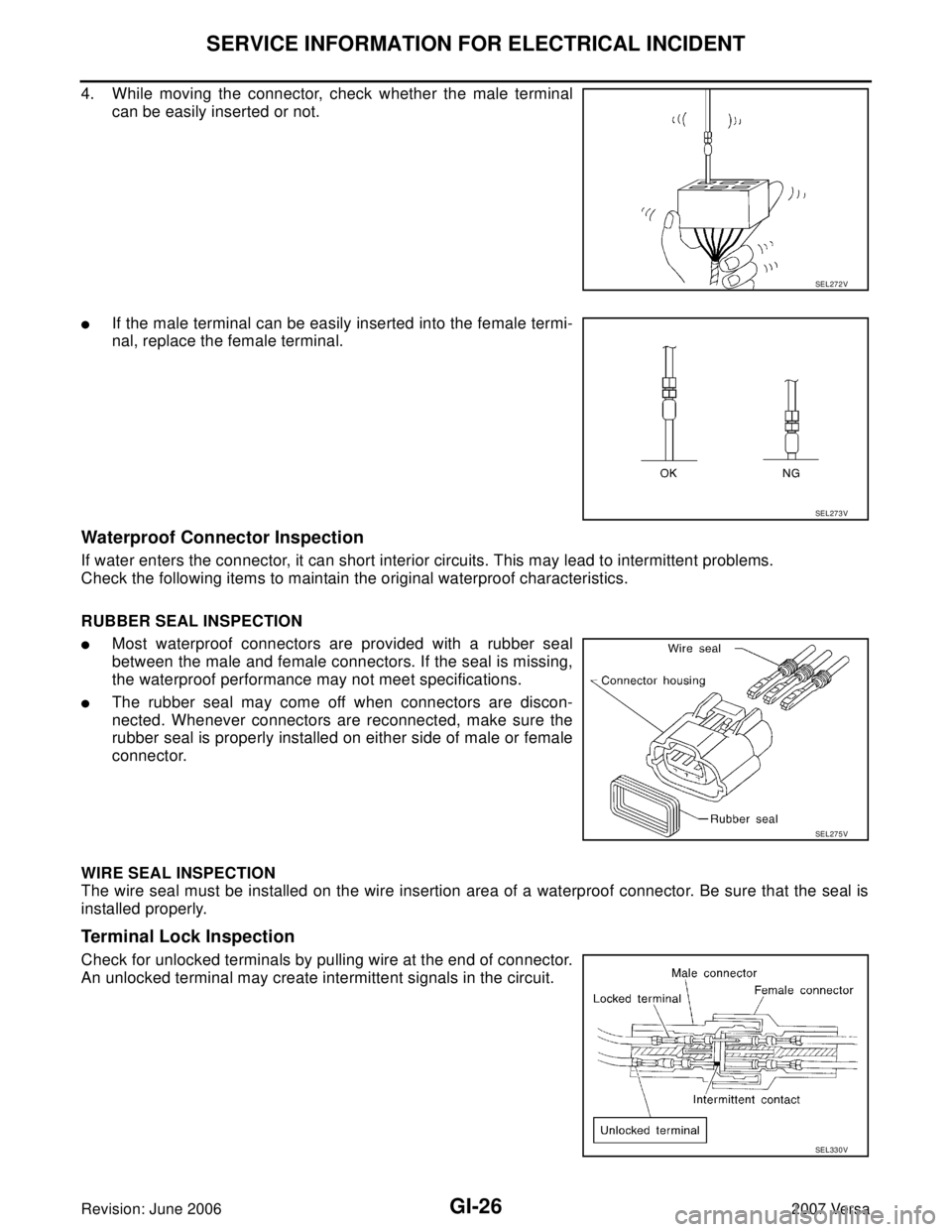
4. While moving the connector, check whether the male terminal
can be easily inserted or not.
�If the male terminal can be easily inserted into the female termi-
nal, replace the female terminal.
Waterproof Connector Inspection
If water enters the connector, it can short interior circuits. This may lead to intermittent problems.
Check the following items to maintain the original waterproof characteristics.
RUBBER SEAL INSPECTION
�Most waterproof connectors are provided with a rubber seal
between the male and female connectors. If the seal is missing,
the waterproof performance may not meet specifications.
�The rubber seal may come off when connectors are discon-
nected. Whenever connectors are reconnected, make sure the
rubber seal is properly installed on either side of male or female
connector.
WIRE SEAL INSPECTION
The wire seal must be installed on the wire insertion area of a waterproof connector. Be sure that the seal is
installed properly.
Terminal Lock Inspection
Check for unlocked terminals by pulling wire at the end of connector.
An unlocked terminal may create intermittent signals in the circuit.
SEL272V
SEL273V
SEL275V
SEL330V
Page 1998 of 2896
SERVICE INFORMATION FOR ELECTRICAL INCIDENT
GI-27
C
D
E
F
G
H
I
J
K
L
MB
GI
Revision: June 20062007 Versa
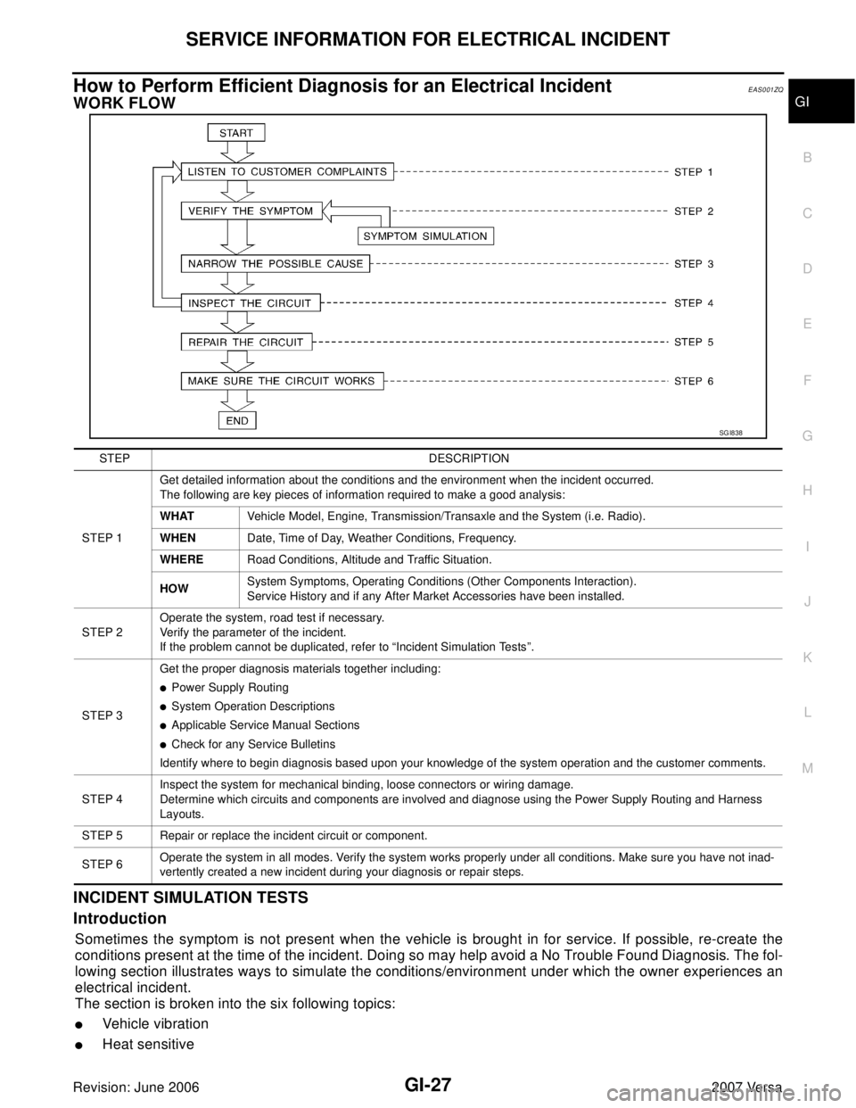
How to Perform Efficient Diagnosis for an Electrical IncidentEAS001ZQ
WORK FLOW
INCIDENT SIMULATION TESTS
Introduction
Sometimes the symptom is not present when the vehicle is brought in for service. If possible, re-create the
conditions present at the time of the incident. Doing so may help avoid a No Trouble Found Diagnosis. The fol-
lowing section illustrates ways to simulate the conditions/environment under which the owner experiences an
electrical incident.
The section is broken into the six following topics:
�Vehicle vibration
�Heat sensitive
SG I8 38
STEP DESCRIPTION
STEP 1Get detailed information about the conditions and the environment when the incident occurred.
The following are key pieces of information required to make a good analysis:
WHATVehicle Model, Engine, Transmission/Transaxle and the System (i.e. Radio).
WHENDate, Time of Day, Weather Conditions, Frequency.
WHERERoad Conditions, Altitude and Traffic Situation.
HOWSystem Symptoms, Operating Conditions (Other Components Interaction).
Service History and if any After Market Accessories have been installed.
STEP 2Operate the system, road test if necessary.
Verify the parameter of the incident.
If the problem cannot be duplicated, refer to “Incident Simulation Tests”.
STEP 3Get the proper diagnosis materials together including:
�Power Supply Routing
�System Operation Descriptions
�Applicable Service Manual Sections
�Check for any Service Bulletins
Identify where to begin diagnosis based upon your knowledge of the system operation and the customer comments.
STEP 4Inspect the system for mechanical binding, loose connectors or wiring damage.
Determine which circuits and components are involved and diagnose using the Power Supply Routing and Harness
Layouts.
STEP 5 Repair or replace the incident circuit or component.
STEP 6Operate the system in all modes. Verify the system works properly under all conditions. Make sure you have not inad-
vertently created a new incident during your diagnosis or repair steps.