Page 2641 of 2896
SUNROOF
RF-23
C
D
E
F
G
H
J
K
L
MA
B
RF
Revision: June 20062007 Versa
1. Glass lid 2. Rear drain assembly 3. Link assembly (RH)
4. Sunroof bracket 5. Wind deflector 6. Drain hose
WIIA1243E
Page 2642 of 2896

RF-24
SUNROOF
Revision: June 20062007 Versa
SUNROOF UNIT ASSEMBLY
Removal
1. Tilt glass lid up, then remove. Refer to RF-25, "GLASS LID" .
2. Position sunroof unit assembly to the fully closed position.
3. Remove the headlining. Refer to EI-39, "
HEADLINING" .
4. Disconnect drain hoses.
5. Remove the screws, then disconnect the sunroof motor assem-
bly.
NOTE:
�Before removing sunroof motor assembly, make sure that
sunroof is fully closed.
�After removing sunroof motor assembly, do not attempt to
rotate sunroof motor as a single unit.
6. Remove the side and front sunroof unit assembly nuts.
7. Remove sunroof bracket bolts, then remove sunroof unit assem-
bly from roof panel.
�Remove sunroof unit assembly through the passenger com-
partment.
CAUTION:
Use care during assembly removal and installation to avoid
damage to seats and trim.
Installation
1. Install sunroof brackets and bolts to the roof panel side only, but
do not tighten.
2. Bring sunroof unit assembly into passenger compartment and
position it so the rear rests on the sunroof brackets.
3. Install sunroof bracket bolts to the sunroof unit assembly side,
but do not tighten.
7. Sunroof unit assembly 8. Sunroof motor assembly 9. Sunshade
10. Sunshade stopper 11. Link assembly (LH)⇐Vehicle front
PIIB4745J
PIIB4747J
PIIB4748J
PIIB4748J
Page 2643 of 2896
SUNROOF
RF-25
C
D
E
F
G
H
J
K
L
MA
B
RF
Revision: June 20062007 Versa
4. Install the front and side sunroof unit assembly nuts, but do not
tighten.
5. Tighten the sunroof unit assembly.
a. First, tighten the sunroof bracket bolts at the vehicle side, then
tighten the bolt on the rail side.
b. Next, tighten the front and side sunroof unit assembly nuts diag-
onally.
6.7. Connect the sunroof motor assembly connector and install the
screws.
8. Install the glass lid. Refer to RF-25, "
GLASS LID" .
9. Connect drain hoses.
10. Install headlining. Refer to EI-39, "
HEADLINING" .
11. Perform fitting adjustment and test for leaks, refer to RF-28, "
Fitting Adjustment" .
GLASS LID
Removal
1. Open the sunshade fully and close the glass lid.
2. Remove glass lid bolts, then remove glass lid.
Installation
1. Position the glass lid on sunroof unit assembly.
PIIB4746J
PIIB4748J
PIIB4745J
PIIB4749J
Page 2645 of 2896

SUNROOF
RF-27
C
D
E
F
G
H
J
K
L
MA
B
RF
Revision: June 20062007 Versa
Installation
CAUTION:
�Before installing the sunroof motor assembly, be sure the link assembly is in the symmetrical and
fully closed position.
�Align the link notch with the hole of the guide track (fully closed: RH and LH).
1. Place the sunroof motor assembly flat onto the sunroof unit assembly surface.
2. Laterally move the assembly little by little so that the gear is completely engaged into the wire and there is
no gap between the sunroof unit assembly and sunroof motor assembly.
3. Install the sunroof motor assembly screws, then connect the harness connector.
4. After installing, perform the initialization procedure. Refer to RF-11, "
INITIALIZATION PROCEDURE" .
LINK ASSEMBLY
Removal
1. Remove sunroof unit assembly. Refer to RF-24, "SUNROOF UNIT ASSEMBLY" .
2. Remove screws, then remove rear drain assembly.
3. Remove sunroof motor assembly. Refer to RF-26, "
SUNROOF MOTOR ASSEMBLY" .
4. Remove link assembly from the rear end of the sunroof frame.
Installation
Installation is in the reverse order of removal.
Page 2648 of 2896
RF-30
SUNROOF
Revision: June 20062007 Versa
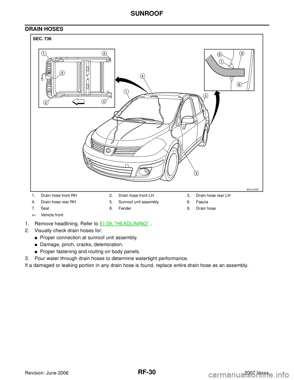
DRAIN HOSES
1. Remove headlining. Refer to EI-39, "HEADLINING" .
2. Visually check drain hoses for:
�Proper connection at sunroof unit assembly.
�Damage, pinch, cracks, deterioration.
�Proper fastening and routing on body panels.
3. Pour water through drain hoses to determine watertight performance.
If a damaged or leaking portion in any drain hose is found, replace entire drain hose as an assembly.
1. Drain hose front RH 2. Drain hose front LH 3. Drain hose rear LH
4. Drain hose rear RH 5. Sunroof unit assembly 6. Fascia
7. Seal 8. Fender 9. Drain hose
⇐Vehicle front
WIIA1253E
Page 2715 of 2896

SQUEAK AND RATTLE TROUBLE DIAGNOSES
SE-7
C
D
E
F
G
H
J
K
L
MA
B
SE
Revision: June 20062007 Versa
TRUNK
Trunk noises are often caused by a loose jack or loose items put into the trunk by the owner.
In addition look for:
1. Trunk lid bumpers out of adjustment
2. Trunk lid striker out of adjustment
3. The trunk lid torsion bars knocking together
4. A loose license plate or bracket
Most of these incidents can be repaired by adjusting, securing or insulating the item(s) or component(s) caus-
ing the noise.
SUNROOF/HEADLINING
Noises in the sunroof/headlining area can often be traced to one of the following:
1. Sunroof lid, rail, linkage or seals making a rattle or light knocking noise
2. Sun visor shaft shaking in the holder
3. Front or rear windshield touching headliner and squeaking
Again, pressing on the components to stop the noise while duplicating the conditions can isolate most of these
incidents. Repairs usually consist of insulating with felt cloth tape.
OVERHEAD CONSOLE (FRONT AND REAR)
Overhead console noises are often caused by the console panel clips not being engaged correctly. Most of
these incidents are repaired by pushing up on the console at the clip locations until the clips engage.
In addition look for:
1. Loose harness or harness connectors.
2. Front console map/reading lamp lense loose.
3. Loose screws at console attachment points.
SEATS
When isolating seat noise it's important to note the position the seat is in and the load placed on the seat when
the noise is present. These conditions should be duplicated when verifying and isolating the cause of the
noise.
Cause of seat noise include:
1. Headrest rods and holder
2. A squeak between the seat pad cushion and frame
3. The rear seatback lock and bracket
These noises can be isolated by moving or pressing on the suspected components while duplicating the con-
ditions under which the noise occurs. Most of these incidents can be repaired by repositioning the component
or applying urethane tape to the contact area.
UNDERHOOD
Some interior noise may be caused by components under the hood or on the engine wall. The noise is then
transmitted into the passenger compartment.
Causes of transmitted underhood noise include:
1. Any component mounted to the engine wall
2. Components that pass through the engine wall
3. Engine wall mounts and connectors
4. Loose radiator mounting pins
5. Hood bumpers out of adjustment
6. Hood striker out of adjustment
These noises can be difficult to isolate since they cannot be reached from the interior of the vehicle. The best
method is to secure, move or insulate one component at a time and test drive the vehicle. Also, engine RPM
or load can be changed to isolate the noise. Repairs can usually be made by moving, adjusting, securing, or
insulating the component causing the noise.

4. Sunroof bracket 5. Wind deflector 6. Drain hose
WIIA1243E")