Page 2114 of 2896

IP-14
INSTRUMENT PANEL ASSEMBLY
Revision: June 20062007 Versa
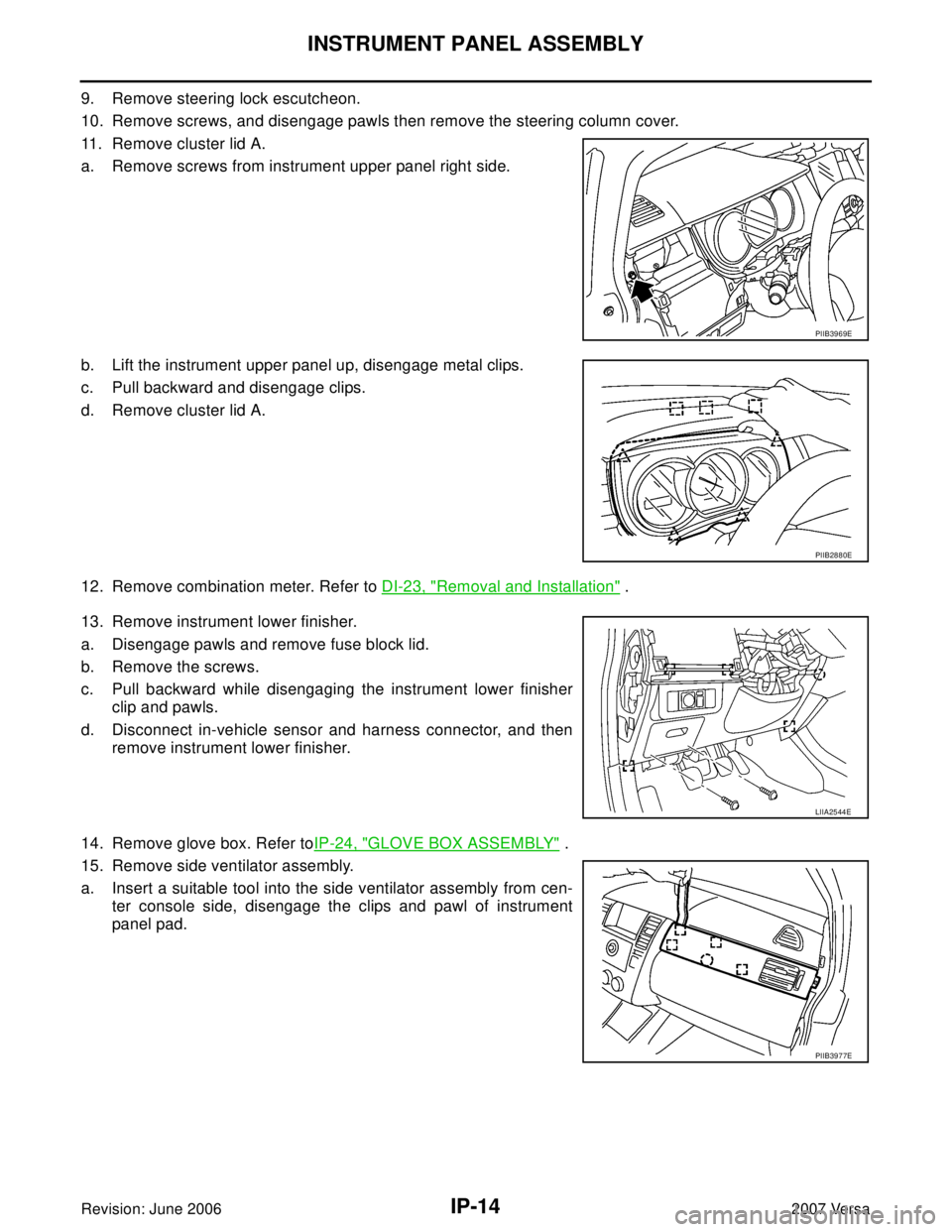
9. Remove steering lock escutcheon.
10. Remove screws, and disengage pawls then remove the steering column cover.
11. Remove cluster lid A.
a. Remove screws from instrument upper panel right side.
b. Lift the instrument upper panel up, disengage metal clips.
c. Pull backward and disengage clips.
d. Remove cluster lid A.
12. Remove combination meter. Refer to DI-23, "
Removal and Installation" .
13. Remove instrument lower finisher.
a. Disengage pawls and remove fuse block lid.
b. Remove the screws.
c. Pull backward while disengaging the instrument lower finisher
clip and pawls.
d. Disconnect in-vehicle sensor and harness connector, and then
remove instrument lower finisher.
14. Remove glove box. Refer toIP-24, "
GLOVE BOX ASSEMBLY" .
15. Remove side ventilator assembly.
a. Insert a suitable tool into the side ventilator assembly from cen-
ter console side, disengage the clips and pawl of instrument
panel pad.
PIIB3969E
PIIB2880E
LIIA2544E
PIIB3977E
Page 2116 of 2896

IP-16
INSTRUMENT PANEL ASSEMBLY
Revision: June 20062007 Versa
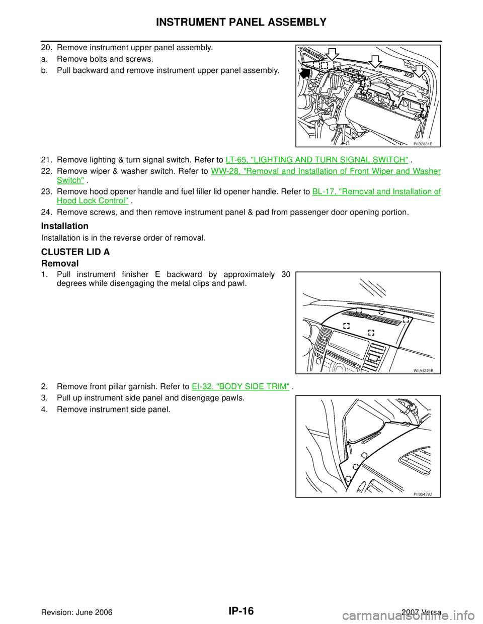
20. Remove instrument upper panel assembly.
a. Remove bolts and screws.
b. Pull backward and remove instrument upper panel assembly.
21. Remove lighting & turn signal switch. Refer to LT-65, "
LIGHTING AND TURN SIGNAL SWITCH" .
22. Remove wiper & washer switch. Refer to WW-28, "
Removal and Installation of Front Wiper and Washer
Switch" .
23. Remove hood opener handle and fuel filler lid opener handle. Refer to BL-17, "
Removal and Installation of
Hood Lock Control" .
24. Remove screws, and then remove instrument panel & pad from passenger door opening portion.
Installation
Installation is in the reverse order of removal.
CLUSTER LID A
Removal
1. Pull instrument finisher E backward by approximately 30
degrees while disengaging the metal clips and pawl.
2. Remove front pillar garnish. Refer to EI-32, "
BODY SIDE TRIM" .
3. Pull up instrument side panel and disengage pawls.
4. Remove instrument side panel.
PIIB2881E
WIIA1224E
PIIB2439J
Page 2118 of 2896
IP-18
INSTRUMENT PANEL ASSEMBLY
Revision: June 20062007 Versa
13. Remove screws from instrument upper panel right side.
14. Lift the instrument upper panel up, disengage metal clips.
15. Pull backward and disengage clips.
16. Remove cluster lid A.
Installation
Installation is in the reverse order of removal.
CLUSTER LID C
Removal
1. Pull instrument finisher E backward by approximately 30
degrees while disengaging the metal clips and pawl.
2. Remove screws.
3. Pull back, and disengage pawls and metal clips.
4. Disconnect harness connector, and then remove cluster lid C.
Installation
Installation is in the reverse order of removal.
PIIB3969E
PIIB2880E
WIIA1224E
WIIA1225E
Page 2120 of 2896
IP-20
INSTRUMENT PANEL ASSEMBLY
Revision: June 20062007 Versa
9. Insert suitable tool into the bottom gap of side ventilator assem-
bly after removing the instrument side mask, push against A and
B as shown to disengage the pawls.
10. Lift the side ventilator up from the bottom, pull backward while
disengaging the side ventilator assembly's upper pawls, and
then remove the side ventilator.
11. Remove screws, and disengage pawls.
12. Remove steering column cover upper.
13. Remove screws from instrument upper panel right side.
14. Lift the instrument upper panel up, disengage metal clips.
15. Pull backward and disengage clips.
16. Remove cluster lid A.
WIIA1226E
PIIB3976E
PIIB3969E
PIIB2880E
Page 2274 of 2896
LT-66
HAZARD SWITCH
Revision: June 20062007 Versa
HAZARD SWITCHPFP:25290
Removal and InstallationEKS00HYI
REMOVAL
1. Remove cluster lid C. Refer to IP-10, "INSTRUMENT PANEL ASSEMBLY" .
2. Disconnect hazard switch connector.
3. Press pawl (A) on reverse side and remove the hazard switch
(1).
INSTALLATION
Installation is in the reverse order of removal.
WKIA5421E
Page 2473 of 2896
CONTROLLER
MTC-61
C
D
E
F
G
H
I
K
L
MA
B
MTC
Revision: June 20062007 Versa
CONTROLLERPFP:28074
Removal and InstallationEJS00580
REMOVAL
1. Remove cluster lid C and instrument finisher D. Refer to IP-10, "INSTRUMENT PANEL ASSEMBLY" .
2. Remove intake door lever knob. Refer to MTC-62, "
Disassembly
and Assembly" .
3. Remove mounting screws and clips, and then remove controller
finisher.
4. Remove mounting screws, and then pull out controller.
5. Remove instrument panel and pad. Refer to IP-10, "
INSTRUMENT PANEL ASSEMBLY" .
6. Remove air mix door cable, mode door cable and intake door cable from A/C unit assembly.
7. Disconnect connector, and then remove controller.
INSTALLATION
Installation is in the reverse order of removal.
CAUTION:
Adjust the door cables during installation. Refer to MTC-69, "
Intake Door Cable Adjustment" , MTC-71,
"Mode Door Cable Adjustment" and MTC-70, "Air Mix Door Cable Adjustment" .
ZJIA0697E
ZJIA0698E
Page 2487 of 2896
DUCTS AND GRILLES
MTC-75
C
D
E
F
G
H
I
K
L
MA
B
MTC
Revision: June 20062007 Versa
DUCTS AND GRILLESPFP:27860
Removal and InstallationEJS0058C
Floor Ducts - Canada Only
1. Side defroster duct (right) 2. Defroster nozzle 3. Side defroster duct (left)
4. Side defroster grille (left) 5. Instrument side panel (left) 6. Instrument panel and pad
7. Side ventilator assembly (left) 8. Cluster lid C 9. Side ventilator assembly (right)
10. Instrument finisher E 11. Instrument side panel (right) 12. Side defroster grille (right)
13. Side ventilator duct (right) 14. Center ventilator duct (right) 15. Center ventilator duct (left)
16. Side ventilator duct (left)
SJIA0657E
WJIA2198E
Page 2488 of 2896
MTC-76
DUCTS AND GRILLES
Revision: June 20062007 Versa
CENTER VENTILATOR GRILLES
Removal
1. Remove cluster lid C. Refer to IP-10, "INSTRUMENT PANEL ASSEMBLY" .
2. Remove center ventilator grills (1) from cluster lid C using suit-
able tool (A).
Installation
Installation is in the reverse order of removal.
SIDE VENTILATOR GRILLES (LH/RH)
Removal
1. Remove side ventilator assembly (LH). Refer to IP-10, "INSTRUMENT PANEL ASSEMBLY" .
2. Remove side ventilator grille (LH) (1) using suitable tool (A).
3. Remove side ventilator assembly (RH). Refer to IP-10, "
INSTRUMENT PANEL ASSEMBLY" .
4. Remove side ventilator grille (RH) (1) using suitable tool (A).
Installation
Installation is in the reverse order of removal.
1. Front floor duct 2. Rear floor duct (left) 3. Clip
4. Rear floor duct (right)
ZJIA0661E
SJIA0658E
SJIA0659E