Page 287 of 2896
AT-274
DISASSEMBLY
Revision: June 20062007 Versa
27. Remove RH differential side oil seal from converter housing
using a flat-bladed screwdriver.
CAUTION:
Be careful not to scratch converter housing.
28. Remove differential lubricant tube (1) and clips (2) from con-
verter housing.
: Bolt (3)
29. Remove oil pump assembly according to the following procedures.
a. Remove O-ring from input shaft assembly (high clutch drum).
b. Remove oil pump assembly fitting bolts, and then remove oil
pump assembly (1) from transaxle case.
c. Remove O-ring from oil pump assembly (1).
SCIA3283E
SCIA7817E
SCIA5634E
SCIA6036J
Page 289 of 2896
AT-276
DISASSEMBLY
Revision: June 20062007 Versa
c. Check brake band facing for damage, cracks, wear or burns.
31. Remove input shaft assembly (high clutch assembly) and reverse clutch assembly according to the follow-
ing procedures.
a. Remove input shaft assembly (high clutch assembly) (1) with
reverse clutch assembly (2).
b. Remove input shaft assembly (high clutch assembly) (1) from
reverse clutch assembly (2).
c. Remove needle bearing (1) from input shaft assembly (high
clutch drum) (2).
�Inspect needle bearing (1) and input shaft assembly (high
clutch drum) (2), and replace if damaged or worn.
SAT0 4 0D
SCIA6038J
SCIA6958E
SCIA6959E
Page 290 of 2896
DISASSEMBLY
AT-277
D
E
F
G
H
I
J
K
L
MA
B
AT
Revision: June 20062007 Versa
32. Remove needle bearing from high clutch hub.
�Inspect needle bearing, and replace if damaged or worn.
33. Remove high clutch hub from front sun gear.
�Inspect high clutch hub, and replace if damaged or worn.
34. Remove needle bearing from front sun gear.
�Inspect needle bearing, and replace if damaged or worn.
35. Remove front sun gear from front planetary carrier.
36. Remove needle bearing (1) from front sun gear (2).
�Inspect needle bearing (1) and front sun gear (2), and
replace if damaged or worn.
SAT3 7 1D
SAT3 7 0D
SAT3 6 9D
SAT3 6 8D
SCIA6960E
Page 291 of 2896
AT-278
DISASSEMBLY
Revision: June 20062007 Versa
37. Remove front planetary carrier and low one-way clutch according to the following procedures.
a. Remove snap ring using a flat-bladed screwdriver.
b. Remove low one-way clutch (1) and front planetary carrier (2) as
a set from transaxle case.
c. Check that low one-way clutch rotates counter-clockwise around
front planetary carrier. Then try to turn it clockwise and check
that it is locked.
�Replace low one-way clutch if necessary.
d. Remove low one-way clutch from front planetary carrier by turn-
ing it in the direction of unlock.
�Inspect low one-way clutch, and replace if damaged or
worn.
e. Remove needle bearing (1) from front planetary carrier (2).
�Inspect needle bearing (1) and front planetary carrier (2),
and replace if damaged or worn.
SCIA3633E
SCIA5896J
SAT0 4 8D
SCIA6047J
Page 293 of 2896
AT-280
DISASSEMBLY
Revision: June 20062007 Versa
d. Check clearance between pinion washer and rear planetary car-
rier using feeler gauge.
�Replace rear planetary carrier if the clearance exceeds
allowable limit.
39. Remove rear internal gear (1) and forward clutch hub (2) as a
set from forward clutch drum.
40. Remove needle bearing (1) from rear internal gear (2).
�Inspect needle bearing (1), and replace if damaged or
worn.
41. Remove overrun clutch hub (1) from forward clutch drum.
42. Remove thrust washer (1) from overrun clutch hub (2).
�Inspect thrust washer (1) and overrun clutch hub (2), and
replace if damaged or worn.Standard clearance and allowable limit:
Refer to AT-382, "
Planetary Carrier" .
SAT0 5 4D
SCIA5897J
SCIA6041J
SCIA5898J
SCIA5899J
Page 294 of 2896
DISASSEMBLY
AT-281
D
E
F
G
H
I
J
K
L
MA
B
AT
Revision: June 20062007 Versa
43. Remove forward clutch assembly and overrun clutch assembly
(1) from transaxle case.
44. Remove needle bearing (1) and thrust washer (2) from bearing
retainer.
�Inspect needle bearing (1) and thrust washer (2), and
replace damaged or worn.
45. Remove output shaft assembly according to the following procedures.
a. Remove side cover fitting bolts.
CAUTION:
�Do not mix bolts A and B.
�Always replace bolts A as they are self-sealing bolts.
b. Remove side cover by lightly tapping it using a soft hammer.
CAUTION:
�Be careful not to drop output shaft assembly. It might
come out when removing side cover.
�Be careful not to damage side cover.
SCIA5900J
SCIA5901J
SCIA7939E
SAT4 3 4D
Page 310 of 2896

REPAIR FOR COMPONENT PARTS
AT-297
D
E
F
G
H
I
J
K
L
MA
B
AT
Revision: June 20062007 Versa
INSPECTION
Control Valve Lower and Upper Bodies
CAUTION:
Be careful not to lose these parts.
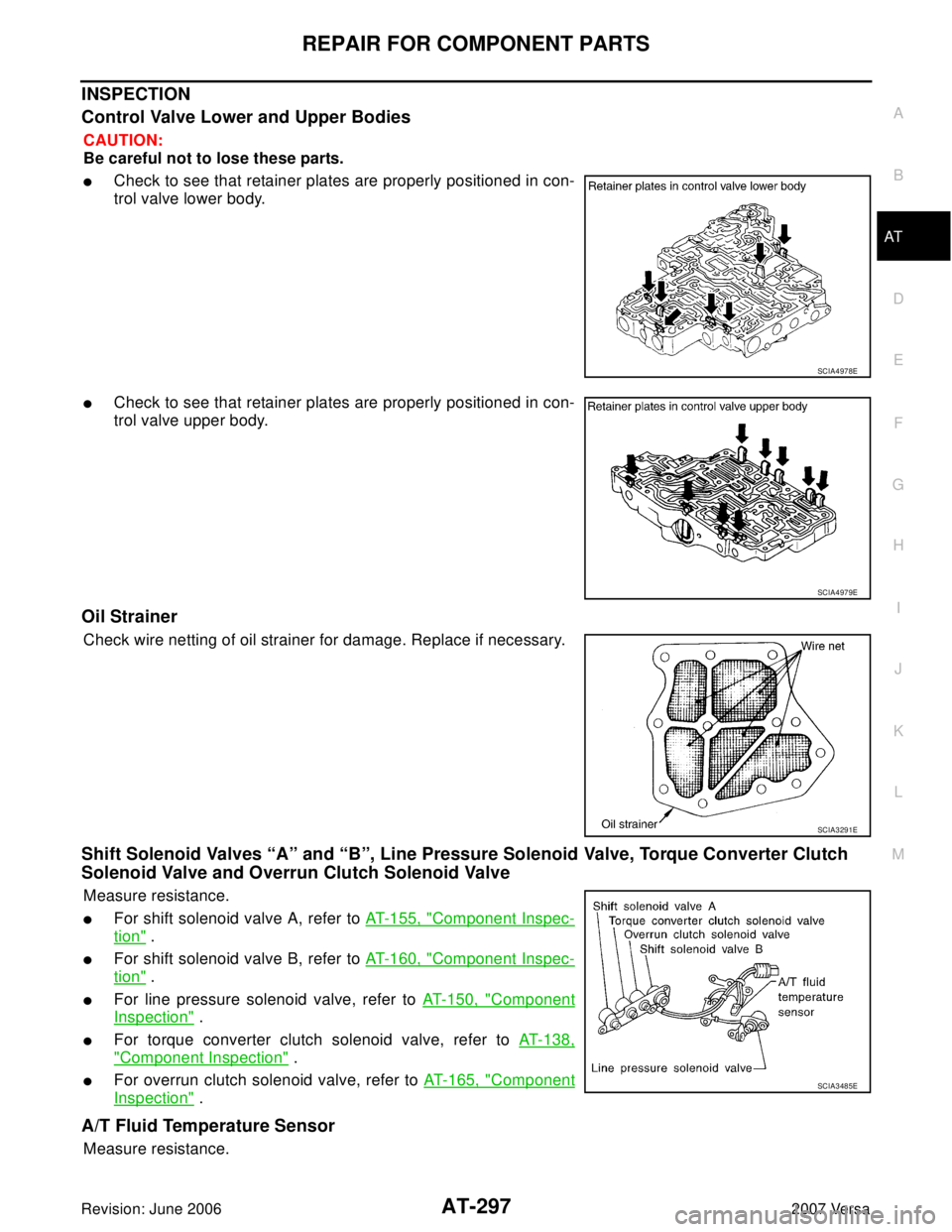
�Check to see that retainer plates are properly positioned in con-
trol valve lower body.
�Check to see that retainer plates are properly positioned in con-
trol valve upper body.
Oil Strainer
Check wire netting of oil strainer for damage. Replace if necessary.
Shift Solenoid Valves “A” and “B”, Line Pressure Solenoid Valve, Torque Converter Clutch
Solenoid Valve and Overrun Clutch Solenoid Valve
Measure resistance.
�For shift solenoid valve A, refer to AT-155, "Component Inspec-
tion" .
�For shift solenoid valve B, refer to AT-160, "Component Inspec-
tion" .
�For line pressure solenoid valve, refer to AT-150, "Component
Inspection" .
�For torque converter clutch solenoid valve, refer to AT-138,
"Component Inspection" .
�For overrun clutch solenoid valve, refer to AT-165, "Component
Inspection" .
A/T Fluid Temperature Sensor
Measure resistance.
SCIA4978E
SCIA4979E
SCIA3291E
SCIA3485E
Page 316 of 2896

REPAIR FOR COMPONENT PARTS
AT-303
D
E
F
G
H
I
J
K
L
MA
B
AT
Revision: June 20062007 Versa
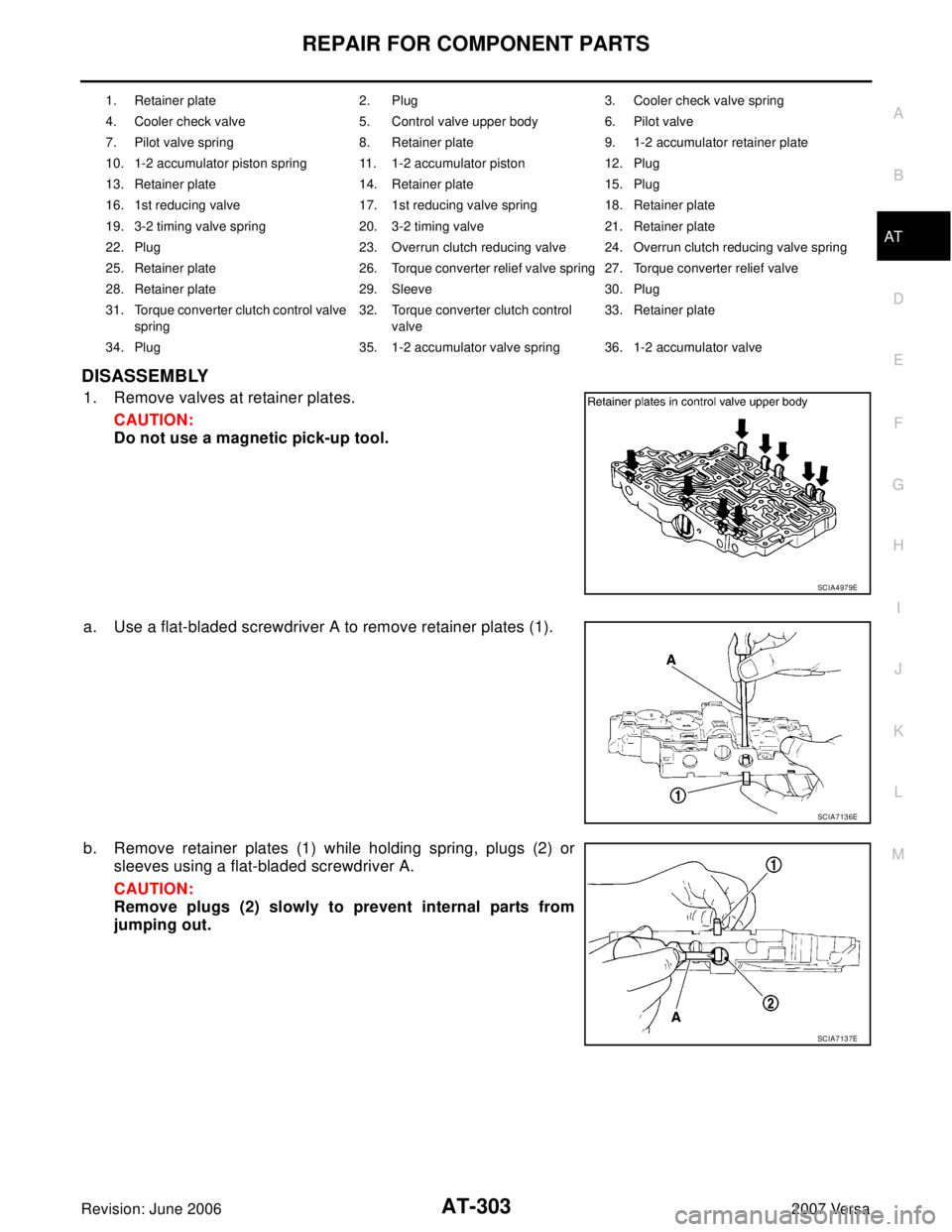
DISASSEMBLY
1. Remove valves at retainer plates.
CAUTION:
Do not use a magnetic pick-up tool.
a. Use a flat-bladed screwdriver A to remove retainer plates (1).
b. Remove retainer plates (1) while holding spring, plugs (2) or
sleeves using a flat-bladed screwdriver A.
CAUTION:
Remove plugs (2) slowly to prevent internal parts from
jumping out.
1. Retainer plate 2. Plug 3. Cooler check valve spring
4. Cooler check valve 5. Control valve upper body 6. Pilot valve
7. Pilot valve spring 8. Retainer plate 9. 1-2 accumulator retainer plate
10. 1-2 accumulator piston spring 11. 1-2 accumulator piston 12. Plug
13. Retainer plate 14. Retainer plate 15. Plug
16. 1st reducing valve 17. 1st reducing valve spring 18. Retainer plate
19. 3-2 timing valve spring 20. 3-2 timing valve 21. Retainer plate
22. Plug 23. Overrun clutch reducing valve 24. Overrun clutch reducing valve spring
25. Retainer plate 26. Torque converter relief valve spring 27. Torque converter relief valve
28. Retainer plate 29. Sleeve 30. Plug
31. Torque converter clutch control valve
spring32. Torque converter clutch control
valve33. Retainer plate
34. Plug 35. 1-2 accumulator valve spring 36. 1-2 accumulator valve
SCIA4979E
SCIA7136E
SCIA7137E