Page 336 of 2896

REPAIR FOR COMPONENT PARTS
AT-323
D
E
F
G
H
I
J
K
L
MA
B
AT
Revision: June 20062007 Versa
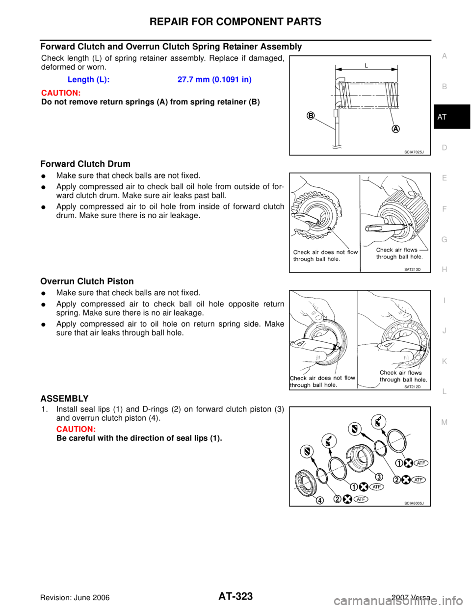
Forward Clutch and Overrun Clutch Spring Retainer Assembly
Check length (L) of spring retainer assembly. Replace if damaged,
deformed or worn.
CAUTION:
Do not remove return springs (A) from spring retainer (B)
Forward Clutch Drum
�Make sure that check balls are not fixed.
�Apply compressed air to check ball oil hole from outside of for-
ward clutch drum. Make sure air leaks past ball.
�Apply compressed air to oil hole from inside of forward clutch
drum. Make sure there is no air leakage.
Overrun Clutch Piston
�Make sure that check balls are not fixed.
�Apply compressed air to check ball oil hole opposite return
spring. Make sure there is no air leakage.
�Apply compressed air to oil hole on return spring side. Make
sure that air leaks through ball hole.
ASSEMBLY
1. Install seal lips (1) and D-rings (2) on forward clutch piston (3)
and overrun clutch piston (4).
CAUTION:
Be careful with the direction of seal lips (1).Length (L): 27.7 mm (0.1091 in)
SCIA7025J
SAT2 1 3D
SAT2 1 2D
SCIA6005J
Page 337 of 2896
AT-324
REPAIR FOR COMPONENT PARTS
Revision: June 20062007 Versa
2. Install overrun clutch piston on forward clutch piston by turning it
slowly.
CAUTION:
Apply ATF to inner surface of forward clutch piston.
3. Install forward clutch piston with overrun clutch piston on for-
ward clutch drum by turning it slowly.
CAUTION:
Apply ATF to inner surface of forward clutch drum.
4. Align notch in forward clutch piston with groove in forward clutch
drum.
5. Install spring retainer assembly (1) on overrun clutch piston (2).
6. Set Tool A on spring retainer assembly, and install snap ring (1)
while compressing spring retainer assembly.
CAUTION:
�Set SST directly over return springs.
�Do not expand snap ring excessively.
SAT2 1 5D
SAT2 1 6D
SAT2 1 7D
SCIA6019J
Tool number: KV31103200 (J-39186)
SCIA7989E
Page 338 of 2896

REPAIR FOR COMPONENT PARTS
AT-325
D
E
F
G
H
I
J
K
L
MA
B
AT
Revision: June 20062007 Versa
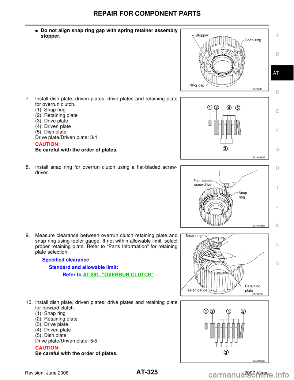
�Do not align snap ring gap with spring retainer assembly
stopper.
7. Install dish plate, driven plates, drive plates and retaining plate
for overrun clutch.
(1): Snap ring
(2): Retaining plate
(3): Drive plate
(4): Driven plate
(5): Dish plate
Drive plate/Driven plate: 3/4
CAUTION:
Be careful with the order of plates.
8. Install snap ring for overrun clutch using a flat-bladed screw-
driver.
9. Measure clearance between overrun clutch retaining plate and
snap ring using feeler gauge. If not within allowable limit, select
proper retaining plate. Refer to “Parts Information” for retaining
plate selection.
10. Install dish plate, driven plates, drive plates and retaining plate
for forward clutch.
(1): Snap ring
(2): Retaining plate
(3): Drive plate
(4): Driven plate
(5): Dish plate
Drive plate/Driven plate: 5/5
CAUTION:
Be careful with the order of plates.
SAT1 3 4F
SCIA5993E
SCIA4895E
Specified clearance
Standard and allowable limit:
Refer to AT-381, "
OVERRUN CLUTCH" .
SAT2 2 7D
SCIA5992E
Page 339 of 2896
AT-326
REPAIR FOR COMPONENT PARTS
Revision: June 20062007 Versa
11. Install snap ring for forward clutch using a flat-bladed screw-
driver.
12. Measure clearance between forward clutch retaining plate and
snap ring using feeler gauge. If not within allowable limit, select
proper retaining plate. Refer to “Parts Information” for retaining
plate selection.
13. Check operation of forward clutch and overrun clutch. Refer to
AT-320, "
DISASSEMBLY" .
SCIA4894E
Specified clearance
Standard and allowable limit:
Refer to AT-381, "
FORWARD CLUTCH" .
SAT2 2 8D
Page 345 of 2896
AT-332
REPAIR FOR COMPONENT PARTS
Revision: June 20062007 Versa
Rear Internal Gear and Forward Clutch HubUCS005WC
COMPONENTS
DISASSEMBLY
1. Remove forward clutch hub from rear internal gear.
2. Remove end bearing (1) from rear internal gear (2).
1. End bearing 2. Forward clutch hub 3. Thrust washer
4. Rear internal gear 5. Forward one-way clutch
Refer to GI section to make sure icons (symbol marks) in the figure. Refer to GI-10, "
Components" .
SCIA5880J
SAT2 5 1D
SCIA7028E
Page 346 of 2896
REPAIR FOR COMPONENT PARTS
AT-333
D
E
F
G
H
I
J
K
L
MA
B
AT
Revision: June 20062007 Versa
3. Remove thrust washer from rear internal gear.
4. Remove end bearing (2) from forward one-way clutch (3).
(1): Forward clutch hub
5. Remove forward one-way clutch from forward clutch hub.
SCIA3691E
SCIA7026E
SAT2 5 5D
Page 347 of 2896
AT-334
REPAIR FOR COMPONENT PARTS
Revision: June 20062007 Versa
INSPECTION
Rear Internal Gear and Forward Clutch Hub
Check rubbing surfaces for wear or damage. Replace if necessary.
(1): Rear internal gear
(2): Forward clutch hub
End Bearings and Forward One-way Clutch
�Check end bearings (1) for deformation and damage. Replace if
necessary.
�Check forward one-way clutch (2) for wear and damage.
Replace if necessary.
ASSEMBLY
1. Install forward one-way clutch on forward clutch hub.
CAUTION:
Be careful with the direction of forward one-way clutch.
2. Install end bearing (2) on forward one-way clutch (3).
(1): Forward clutch hub
SCIA5881J
SCIA7027E
SAT9 7 6H
SCIA7026E
Page 348 of 2896
REPAIR FOR COMPONENT PARTS
AT-335
D
E
F
G
H
I
J
K
L
MA
B
AT
Revision: June 20062007 Versa
3. Install thrust washer on rear internal gear.
CAUTION:
Align pawls of thrust washer with holes of rear internal
gear.
4. Install end bearing (1) on rear internal gear (2).
5. Install forward clutch hub on rear internal gear.
CAUTION:
�Check operation of forward one-way clutch.
Hold rear internal gear and turn forward clutch hub.
Check forward clutch hub for correct locking and unlock-
ing directions.
�If not as shown in figure, check the installation direction
of forward one-way clutch.
SCIA3690E
SCIA7028E
AAT4 2 6