Page 335 of 2896

AT-322
REPAIR FOR COMPONENT PARTS
Revision: June 20062007 Versa
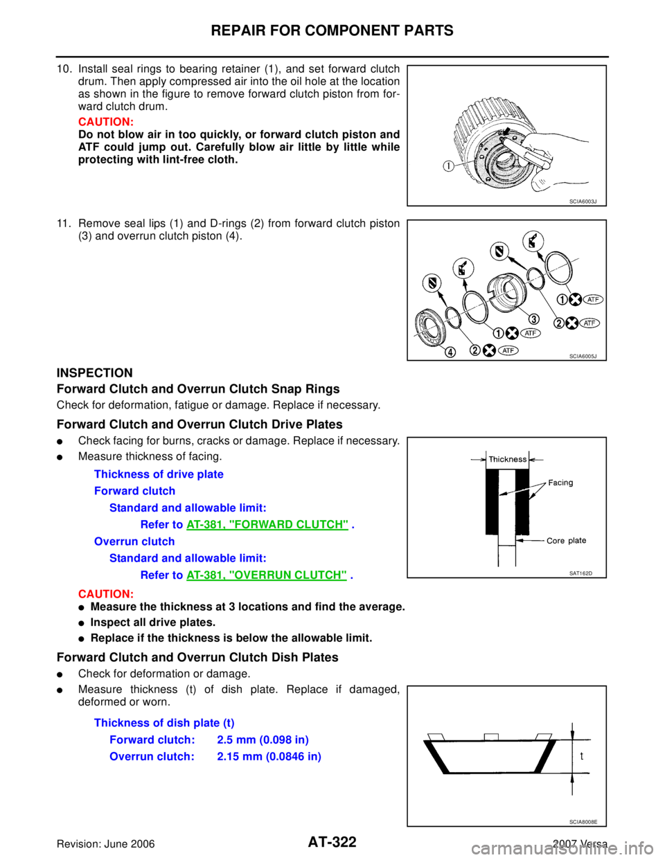
10. Install seal rings to bearing retainer (1), and set forward clutch
drum. Then apply compressed air into the oil hole at the location
as shown in the figure to remove forward clutch piston from for-
ward clutch drum.
CAUTION:
Do not blow air in too quickly, or forward clutch piston and
ATF could jump out. Carefully blow air little by little while
protecting with lint-free cloth.
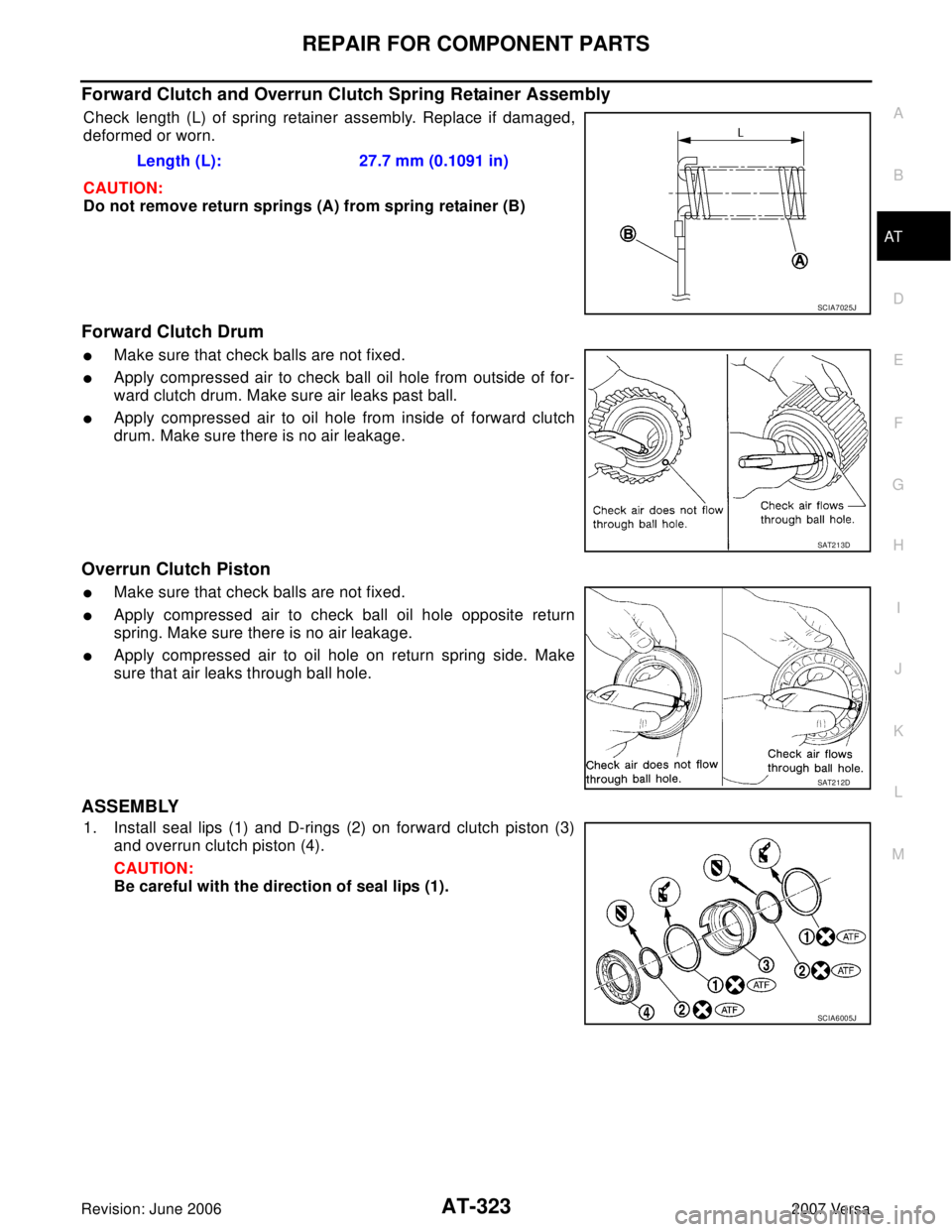
11. Remove seal lips (1) and D-rings (2) from forward clutch piston
(3) and overrun clutch piston (4).
INSPECTION
Forward Clutch and Overrun Clutch Snap Rings
Check for deformation, fatigue or damage. Replace if necessary.
Forward Clutch and Overrun Clutch Drive Plates
�Check facing for burns, cracks or damage. Replace if necessary.
�Measure thickness of facing.
CAUTION:
�Measure the thickness at 3 locations and find the average.
�Inspect all drive plates.
�Replace if the thickness is below the allowable limit.
Forward Clutch and Overrun Clutch Dish Plates
�Check for deformation or damage.
�Measure thickness (t) of dish plate. Replace if damaged,
deformed or worn.
SCIA6003J
SCIA6005J
Thickness of drive plate
Forward clutch
Standard and allowable limit:
Refer to AT-381, "
FORWARD CLUTCH" .
Overrun clutch
Standard and allowable limit:
Refer to AT-381, "
OVERRUN CLUTCH" .SAT1 6 2D
Thickness of dish plate (t)
Forward clutch: 2.5 mm (0.098 in)
Overrun clutch: 2.15 mm (0.0846 in)
SCIA8008E
Page 336 of 2896

REPAIR FOR COMPONENT PARTS
AT-323
D
E
F
G
H
I
J
K
L
MA
B
AT
Revision: June 20062007 Versa
Forward Clutch and Overrun Clutch Spring Retainer Assembly
Check length (L) of spring retainer assembly. Replace if damaged,
deformed or worn.
CAUTION:
Do not remove return springs (A) from spring retainer (B)
Forward Clutch Drum
�Make sure that check balls are not fixed.
�Apply compressed air to check ball oil hole from outside of for-
ward clutch drum. Make sure air leaks past ball.
�Apply compressed air to oil hole from inside of forward clutch
drum. Make sure there is no air leakage.
Overrun Clutch Piston
�Make sure that check balls are not fixed.
�Apply compressed air to check ball oil hole opposite return
spring. Make sure there is no air leakage.
�Apply compressed air to oil hole on return spring side. Make
sure that air leaks through ball hole.
ASSEMBLY
1. Install seal lips (1) and D-rings (2) on forward clutch piston (3)
and overrun clutch piston (4).
CAUTION:
Be careful with the direction of seal lips (1).Length (L): 27.7 mm (0.1091 in)
SCIA7025J
SAT2 1 3D
SAT2 1 2D
SCIA6005J
Page 340 of 2896
REPAIR FOR COMPONENT PARTS
AT-327
D
E
F
G
H
I
J
K
L
MA
B
AT
Revision: June 20062007 Versa
Low & Reverse BrakeUCS005WB
COMPONENTS
DISASSEMBLY
1. Check operation of low & reverse brake.
a. Apply compressed air into oil hole of transaxle case at the loca-
tion as shown in the figure.
b. Check to see that retaining plate moves to snap ring.
c. If retaining plate does not contact snap ring:
�D-ring might be damaged.
�Seal lip might be damaged.
2. Remove snap ring (1) using a flat-bladed screwdriver A.
3. Remove retaining plates, drive plates, driven plates, dish plates.
1. Seal lip 2. D-ring 3. Low & reverse brake piston
4. Spring retainer assembly 5. Snap ring 6. Driven plate
7. Retaining plate 8. Driven plate 9. Retaining plate
10. Snap ring 11. Drive plate 12. Dish plate
Refer to GI section to make sure icons (symbol marks) in the figure. Refer to GI-10, "
Components" .
SCIA6007J
SAT2 3 0D
SCIA7039E
Page 341 of 2896

AT-328
REPAIR FOR COMPONENT PARTS
Revision: June 20062007 Versa
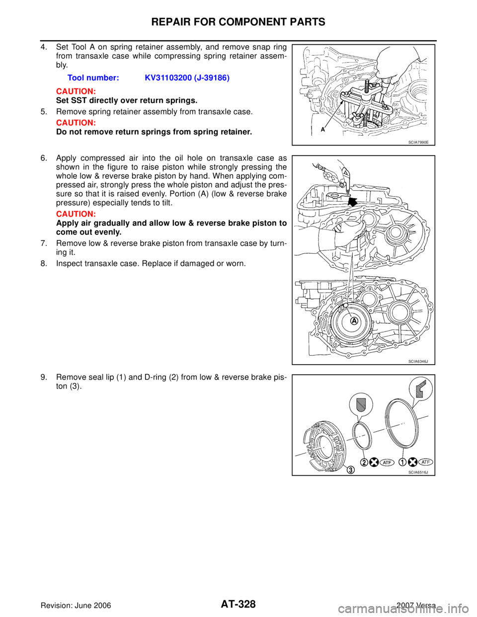
4. Set Tool A on spring retainer assembly, and remove snap ring
from transaxle case while compressing spring retainer assem-
bly.
CAUTION:
Set SST directly over return springs.
5. Remove spring retainer assembly from transaxle case.
CAUTION:
Do not remove return springs from spring retainer.
6. Apply compressed air into the oil hole on transaxle case as
shown in the figure to raise piston while strongly pressing the
whole low & reverse brake piston by hand. When applying com-
pressed air, strongly press the whole piston and adjust the pres-
sure so that it is raised evenly. Portion (A) (low & reverse brake
pressure) especially tends to tilt.
CAUTION:
Apply air gradually and allow low & reverse brake piston to
come out evenly.
7. Remove low & reverse brake piston from transaxle case by turn-
ing it.
8. Inspect transaxle case. Replace if damaged or worn.
9. Remove seal lip (1) and D-ring (2) from low & reverse brake pis-
ton (3).Tool number: KV31103200 (J-39186)
SCIA7990E
SCIA6346J
SCIA6516J
Page 356 of 2896

REPAIR FOR COMPONENT PARTS
AT-343
D
E
F
G
H
I
J
K
L
MA
B
AT
Revision: June 20062007 Versa
Band Servo Piston AssemblyUCS005WE
COMPONENTS
DISASSEMBLY
1. Push in OD servo piston assembly using a puller A (commercial
service tool) and a suitable drift B, and then remove snap ring
(1) from transaxle case using a flat-bladed screwdriver C.
2. Apply compressed air into the oil hole as shown in the figure to
remove OD servo piston assembly and band servo piston
assembly.
CAUTION:
Do not blow air in too quickly, or OD servo piston assembly,
band servo piston assembly and ATF could jump out. Care-
fully blow air little by little while protecting with lint-free
cloth A.
3. Remove 2nd servo return spring from transaxle case.
1. Lock nut 2. Anchor end pin 3. O-ring
4. Servo piston retainer 5. D-ring 6. OD servo piston
7. O-ring 8. Snap ring 9. OD servo piston retainer
10. E-ring 11. Spring retainer 12. OD servo return spring
13. D-ring 14. Band servo piston 15. Band servo thrust washer
16. Band servo piston stem 17. 2nd servo return spring
Refer to GI section to make sure icons (symbol marks) in the figure. Refer to GI-10, "
Components" .
SCIA7965E
SCIA7050E
SCIA7051E
Page 367 of 2896

AT-354
ASSEMBLY
Revision: June 20062007 Versa
ASSEMBLYPFP:00000
Assembly (1)UCS005WG
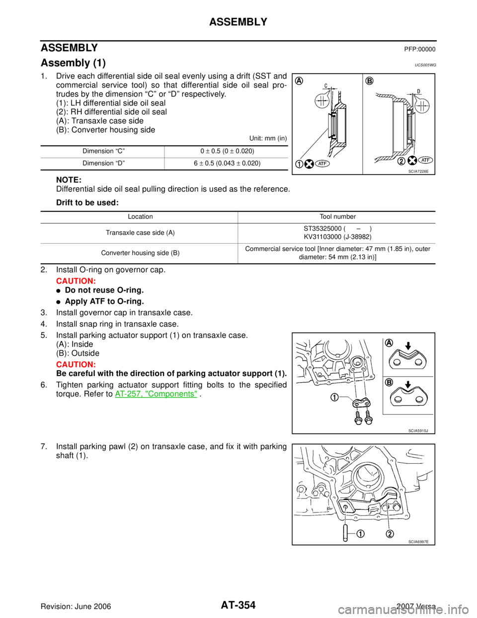
1. Drive each differential side oil seal evenly using a drift (SST and
commercial service tool) so that differential side oil seal pro-
trudes by the dimension “C” or “D” respectively.
(1): LH differential side oil seal
(2): RH differential side oil seal
(A): Transaxle case side
(B): Converter housing side
Unit: mm (in)
NOTE:
Differential side oil seal pulling direction is used as the reference.
Drift to be used:
2. Install O-ring on governor cap.
CAUTION:
�Do not reuse O-ring.
�Apply ATF to O-ring.
3. Install governor cap in transaxle case.
4. Install snap ring in transaxle case.
5. Install parking actuator support (1) on transaxle case.
(A): Inside
(B): Outside
CAUTION:
Be careful with the direction of parking actuator support (1).
6. Tighten parking actuator support fitting bolts to the specified
torque. Refer to AT-257, "
Components" .
7. Install parking pawl (2) on transaxle case, and fix it with parking
shaft (1).
Dimension “C” 0 ± 0.5 (0 ± 0.020)
Dimension “D” 6 ± 0.5 (0.043 ± 0.020)
SCIA7226E
Location Tool number
Transaxle case side (A)ST35325000 ( – )
KV31103000 (J-38982)
Converter housing side (B)Commercial service tool [Inner diameter: 47 mm (1.85 in), outer
diameter: 54 mm (2.13 in)]
SCIA5910J
SCIA6997E
Page 374 of 2896

ASSEMBLY
AT-361
D
E
F
G
H
I
J
K
L
MA
B
AT
Revision: June 20062007 Versa
�Completely remove all moisture, oil and old sealant, etc. from the transaxle case and side cover
mounting surfaces.
3. Fit mounting part of output shaft bearing on side cover to output
shaft bearing, and after adjusting knock pin position, install it
with light taps of a soft hammer and things like that.
CAUTION:
When installing, to avoid getting damaged and deformed,
set mounting part straight to parallel with the mounting sur-
face.
4. Tighten side cover fitting bolts to specified torque. Refer to AT-
257, "Components" .
CAUTION:
�Do not mix bolts A and B.
�Always replace bolts A as they are self-sealing bolts.
Assembly (2)UCS005WI
1. Remove paper rolled around bearing retainer.
2. Install thrust washer on bearing retainer.
CAUTION:
Align pawls of thrust washer with holes of bearing retainer.
3. Install forward clutch assembly and overrun clutch assembly (1)
into transaxle case.
CAUTION:
�Align teeth of low & reverse brake drive plates before
installing.
�Make sure that bearing retainer seal rings are not spread.
SAT4 4 2D
SCIA7939E
SAT3 5 4D
SCIA5900J
Page 379 of 2896
AT-366
ASSEMBLY
Revision: June 20062007 Versa
Adjustment (2)UCS005W J
When any parts listed below are replaced, adjust total end play and reverse clutch end play.
TOTAL END PLAY
�Measure clearance between reverse clutch drum and needle
bearing for oil pump cover.
�Select proper thickness of bearing race so that end play is within
specifications.
1. Measure dimensions “K” and “L”, and then calculate dimension
“J”.
a. Measure dimension “K”.
Part name Total end play Reverse clutch end play
Transaxle case��
Overrun clutch hub��
Rear internal gear��
Rear planetary carrier��
Rear sun gear��
Front planetary carrier��
Front sun gear��
High clutch hub��
Input shaft assembly (high clutch drum)��
Oil pump cover��
Reverse clutch drum —�
SCIA3661E
SCIA3662E
SCIA3663E