Page 1653 of 2896
EC-484Revision: June 2006
DTC P1574 ASCD VEHICLE SPEED SENSOR
2007 Versa
Diagnostic ProcedureUBS00QLW
1. CHECK DTC WITH TCM
Check DTC with TCM. Refer to AT-39, "
ON BOARD DIAGNOSTIC (OBD) SYSTEM" (A/T) or CVT-30, "ON
BOARD DIAGNOSTIC (OBD) SYSTEM" (CVT).
OK or NG
OK >> GO TO 2.
NG >> Perform trouble shooting relevant to DTC indicated.
2. CHECK DTC WITH “ABS ACTUATOR AND ELECTRIC UNIT”
Refer to BRC-8, "
TROUBLE DIAGNOSIS" .
OK or NG
OK >> GO TO 3.
NG >> Repair or replace.
3. CHECK COMBINATION METER
Check combination meter function.
Refer to DI-5, "
COMBINATION METERS" .
>>INSPECTION END
Page 1779 of 2896
EI-14
FRONT BUMPER
Revision: June 20062007 Versa
FRONT BUMPERPFP:F2022
Removal and Installation EIS0096K
1. Bumper stay RH 2. Bumper reinforcement (production) 3. Bumper energy absorber
4. Engine undercover 5. Front valance 6. Front bumper fascia
7. Access cover 8. Fog lamp opening finisher (without
fog lamps)9. Fog lamp opening finisher (with fog
lamps)
10. Fog lamp assembly 11. Bumper side retainer 12. Bumper stay LH (service)
LIIA2562E
Page 1780 of 2896

FRONT BUMPER
EI-15
C
D
E
F
G
H
J
K
L
MA
B
EI
Revision: June 20062007 Versa
CAUTION:
Bumper fascia is made of resin. Do not apply strong force to it, and be careful to prevent contact with
oil.
REMOVAL
1. Open hood.
2. Remove front grille. Refer to EI-19, "
FRONT GRILLE" .
3. Remove front fender protectors RH/LH. Refer to EI-22, "
FENDER PROTECTOR" .
4. Remove front valance and engine undercover.
5. Remove screws of front bumper fascia RH/LH.
6. Pull the outboard edge of front bumper fascia away from vehicle
to disengage from the bumper side retainer.
7. Disconnect fog lamp harness connector RH/LH (if equipped).
8. Remove the front bumper fascia.
9. Remove fog lamp opening finisher and fog lamp assembly RH/
LH (if equipped). Refer to LT-50, "
Removal and Installation" .
10. Remove bumper energy absorber.
11. Remove RH/LH air guide mounting clips of bumper reinforcement.
12. Remove the nuts, then remove bumper reinforcement and bumper stay(s):
�For production, bumper stay LH is part of bumper reinforcement.
�For service, bumper stay RH/LH are separate assemblies.
13. Remove bumper side bracket RH/LH after front bumper fascia removal.
PIIB2537J
PIIB2538J
PIIB2543J
Page 1782 of 2896
REAR BUMPER
EI-17
C
D
E
F
G
H
J
K
L
MA
B
EI
Revision: June 20062007 Versa
REAR BUMPERPFP:H5022
Removal and InstallationEIS0096L
1. Bumper side bracket 2. Rear bumper closing 3. Spring nut
4. Bumper reinforcement bracket 5. Rear bumper reinforcement 6. Energy absorbing foam
7. Rear bumper fascia 8. Rear bumper upper retainer 9. Clip C205
LIIA2563E
Page 1783 of 2896
EI-18
REAR BUMPER
Revision: June 20062007 Versa
REMOVAL
1. Open back door.
2. Remove rear combination lamp RH/LH. Refer to LT- 8 7 , "
Removal and Installation" .
3. Remove rear bumper fascia lower clips and screws RH/LH.
4. Remove rear fender protector. Refer to EI-22, "
FENDER PROTECTOR" .
5. Pull the rear bumper fascia side outward to disengage the
bumper side bracket.
6. Remove rear bumper fascia upper clips and screws.
7. Release rear bumper upper retainer, then pull rear bumper fas-
cia outward away from rear of vehicle.
8. Disconnect license lamp connector.
9. Remove energy absorbing foam and rear bumper reinforcement.
10. Remove the screws, then remove the rear bumper closing RH/LH and rear bumper fascia.
11. Remove the bumper side bracket (1) RH/LH.
INSTALLATION
Installation is in the reverse order of removal.
LIIA2579E
LIIA2580E
LIIA2581E
Page 1807 of 2896
EI-42
LUGGAGE FLOOR TRIM
Revision: June 20062007 Versa
LUGGAGE FLOOR TRIMPFP:84920
Removal and InstallationEIS00970
1. Luggage side lower finisher RH 2. Access cover 3. Shock absorber cover RH
4. Luggage floor center board 5. Luggage floor spacer 6. Tonneau board
7. Clip C101 8. Luggage side lower finisher LH 9. Cargo lamp
10. Shock absorber cover LH 11. Luggage rear plate 12. Striker cover plate
Pawl Metal clip Clip C101
⇐Vehicle front
LIIA2578E
Page 1826 of 2896
AIR CLEANER AND AIR DUCT
EM-17
C
D
E
F
G
H
I
J
K
L
MA
EM
Revision: June 20062007 Versa
�Align marks.
�Attach each joint securely.
�Screw clamps firmly.
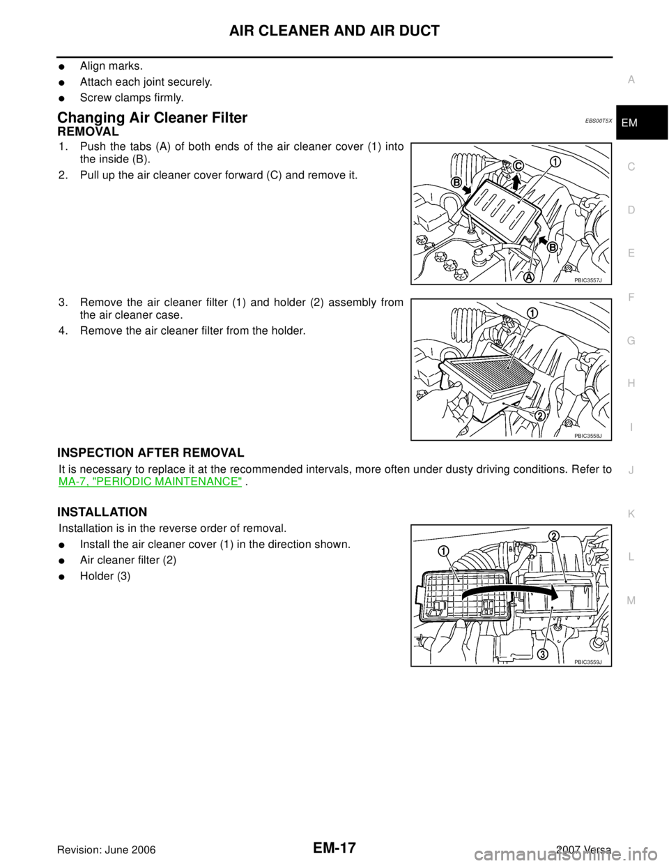
Changing Air Cleaner FilterEBS00T5X
REMOVAL
1. Push the tabs (A) of both ends of the air cleaner cover (1) into
the inside (B).
2. Pull up the air cleaner cover forward (C) and remove it.
3. Remove the air cleaner filter (1) and holder (2) assembly from
the air cleaner case.
4. Remove the air cleaner filter from the holder.
INSPECTION AFTER REMOVAL
It is necessary to replace it at the recommended intervals, more often under dusty driving conditions. Refer to
MA-7, "
PERIODIC MAINTENANCE" .
INSTALLATION
Installation is in the reverse order of removal.
�Install the air cleaner cover (1) in the direction shown.
�Air cleaner filter (2)
�Holder (3)
PBIC3557J
PBIC3558J
PBIC3559J
Page 1834 of 2896

OIL PAN
EM-25
C
D
E
F
G
H
I
J
K
L
MA
EM
Revision: June 20062007 Versa
1. Drain engine oil. Refer to LU-5, "ENGINE OIL" .
2. Remove engine and transaxle assembly. Refer to EM-73
.
3. Remove oil filter using Tool.
CAUTION:
When removing, prepare a shop cloth to absorb any engine oil leakage or spillage.
4. Remove oil pan (lower) bolts in reverse order as shown.
5. After removing the bolts and nuts, separate the mating surface
and remove the sealant using Tool.
CAUTION:
Be careful not to damage the mating surfaces.
6. Remove the following parts:
�Flywheel (M/T models) or drive plate (A/T or CVT models); Refer to EM-77, "CYLINDER BLOCK" .
�Front cover, timing chain, oil pump drive chain; Refer to EM-37, "TIMING CHAIN" .
7. Remove oil pump.
�Loosen bolts in reverse order as shown.
8. Remove oil pan (lower) bolts in reverse order as shown.Tool number : KV10115801 ( — )
: Engine front
PBIC3146J
Tool number : KV10111100 (J-37228)
WBIA0566E
1 : Oil pump
2 : Oil pan (upper)
: Engine front
PBIC3532J
: Engine front
PBIC3533J
 SYSTEM\" (A/")
 3. Bumper energy absorber
4. Engine unde")