Page 72 of 1226

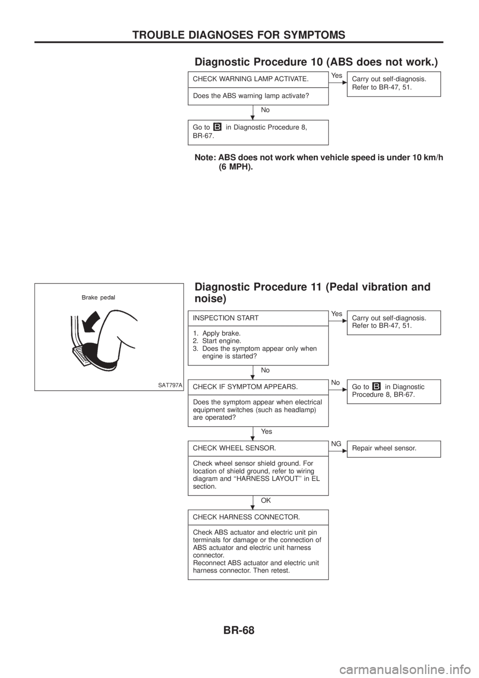
Diagnostic Procedure 10 (ABS does not work.)
CHECK WARNING LAMP ACTIVATE.
- ---------------------------------------------------------------------------------------------------------------------------------------------------------------------------------------------------------------------------------------------------------------------------------------------------------------
Does the ABS warning lamp activate?
No
cYe s Carry out self-diagnosis.
Refer to BR-47, 51.
Go toin Diagnostic Procedure 8,
BR-67.
Note: ABS does not work when vehicle speed is under 10 km/h (6 MPH).
Diagnostic Procedure 11 (Pedal vibration and
noise)
INSPECTION START
- ---------------------------------------------------------------------------------------------------------------------------------------------------------------------------------------------------------------------------------------------------------------------------------------------------------------
1. Apply brake.
2. Start engine.
3. Does the symptom appear only when engine is started?
No
cYe s Carry out self-diagnosis.
Refer to BR-47, 51.
CHECK IF SYMPTOM APPEARS.
- ---------------------------------------------------------------------------------------------------------------------------------------------------------------------------------------------------------------------------------------------------------------------------------------------------------------
Does the symptom appear when electrical
equipment switches (such as headlamp)
are operated?
Ye s
cNo Go toin Diagnostic
Procedure 8, BR-67.
CHECK WHEEL SENSOR.
- ---------------------------------------------------------------------------------------------------------------------------------------------------------------------------------------------------------------------------------------------------------------------------------------------------------------
Check wheel sensor shield ground. For
location of shield ground, refer to wiring
diagram and ``HARNESS LAYOUT'' in EL
section.
OK
cNG Repair wheel sensor.
CHECK HARNESS CONNECTOR.
- ---------------------------------------------------------------------------------------------------------------------------------------------------------------------------------------------------------------------------------------------------------------------------------------------------------------
Check ABS actuator and electric unit pin
terminals for damage or the connection of
ABS actuator and electric unit harness
connector.
Reconnect ABS actuator and electric unit
harness connector. Then retest.
SAT797A
.
.
.
.
TROUBLE DIAGNOSES FOR SYMPTOMS
BR-68
Page 82 of 1226

Body Front End
+When removing or installing hood, place a cloth or other padding on front fender panel and cowl top. This
prevents vehicle body from being scratched.
+Bumper fascia is made of plastic. Do not use excessive force and be sure to keep oil away from it.
+Hood adjustment: Adjust at hinge portion.
+Hood lock adjustment: After adjusting, check hood lock control operation. Apply a coat of grease to hood
locks engaging mechanism.
+Hood opener: Do not attempt to bend cable forcibly. Doing so increases effort required to unlock hood.
REMOVAL Ð Front bumper assembly
V1Remove front guard bar. Refer to ``EXTERIOR'' for details, BT-26.
V2Remove left and right headlamp wipers (on models with headlamp wipers).
V3Remove clips securing front grille and remove the front grille.
V4Remove screws and bolts securing left and right front bumper side bracket.
V5Remove bolts securing bumper lower to engine under cover.
V6Remove bolts securing left and right front bumper stay upper (without winch).
V7Remove bolts securing left and right front bumper stay side.
V8Extract bumper assembly.
SBT518
BODY END
BT-4
Page 98 of 1226
Roof Trim
REMOVAL Ð Headlining (WAGON)
V1Remove front, rear and 3rd seats. Refer to ``SEAT'' for details, BT-32.
V2Remove front, rear and 3rd seat belts. Refer to ``SEAT BELTS'' in RS section for details.
V3Remove body side trim. Refer to ``Side and Floor Trim'' for details, BT-14.
V4Remove roof console assembly, then disconnect connectors.
V5Remove inside mirror assembly.
V6Remove sun visors.
V7Remove interior lamp assembly.
V8Remove luggage room lamp assembly.
V9Remove assist grips.
V10Remove clips securing headlining.
V11Remove rear headlining from vehicle through either back door.
V12Remove front headlining from vehicle through either back door.
SBT531
INTERIOR TRIM
BT-20
Page 100 of 1226
REMOVAL Ð Headlining (HARDTOP)
V1Remove front and rear seats. Refer to ``SEAT'' for details, BT-32.
V2Remove front and rear seat belts. Refer to ``SEAT BELTS'' in RS section for details.
V3Remove body side trim. Refer to ``Side and Floor Trim'' for details, BT-14.
V4Remove roof console assembly, then disconnect connector.
V5Remove inside mirror assembly.
V6Remove sun visors.
V7Remove interior lamp assembly.
V8Remove assist grips.
V9Remove clips securing headlining from vehicle through either back door.
SBT532
INTERIOR TRIM
Roof Trim (Cont'd)
BT-22
Page 118 of 1226
REMOVAL
+After any adjustment, check sunroof operation and lid alignment.
+Handle ®nisher plate and glass lid with care so as not to cause damage.
+It is desirable for easy installation to mark each point before removal.
CAUTION:
Always work with a helper.
Shade assemblySunroof frame assemblyWind de¯ector assemblyLid assemblyMotor assembly
Tilt glass lid up.
V1Side trim
V2Sunroof lid mounting nuts
V3Lid assembly
V4Rear drain mounting screws
V5Rear drain assembly
Use the sunroof switch to tilt the glass lid downward and slide it about 300 mm
(11.81 in) backward.
V6Wind de¯ector holder
V7Wind de¯ector mounting screws
V8Wind de¯ector assembly
Sunroof switch/interior accessories/headlining
+For details, refer to ``Roof Trim'' in ``INTERIOR TRIM'', BT-20.
V9Motor switch bracket
V10Motor assembly
V11Drain hoses
V12Sunroof unit bracket
V13Sunroof frame assembly
V14Shade stopper
V15Shade assembly
SUNROOF
BT-40
Page 146 of 1226
Clutch Disc
INSPECTION
Check clutch disc for wear of facing.
Wear limit of facing surface to rivet head:
0.3 mm (0.012 in)
+Check clutch disc for backlash of spline and runout of facing.
Maximum backlash of spline (at outer edge of disc):
Model 240
1.0 mm (0.039 in)
Runout limit:
Model 240
0.7 mm (0.028 in)
Distance of runout check point (from hub center):
Model 240
115.0 mm (4.53 in)
+Check clutch disc for burns, discoloration or oil or grease leak-
age. Replace if necessary.
INSTALLATION
+Apply recommended grease to contact surface of spline por-
tion.
Too much lubricant might cause clutch disc facing damage.
SCL778
SCL780
SCL779
CLUTCH DISC AND CLUTCH COVER
CL-13
Page 149 of 1226

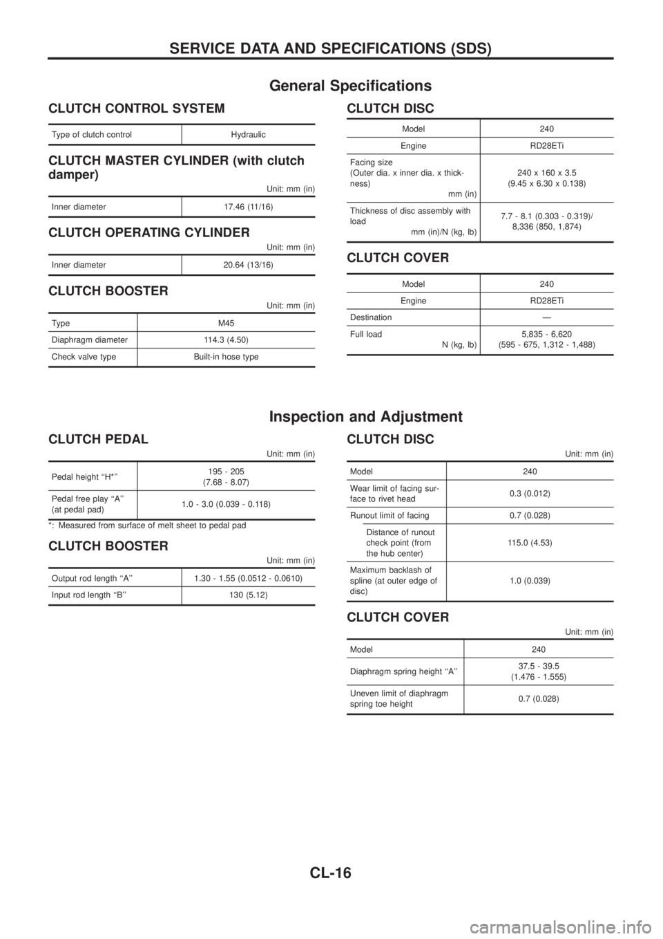
General Speci®cations
CLUTCH CONTROL SYSTEM
Type of clutch control Hydraulic
CLUTCH MASTER CYLINDER (with clutch
damper)
Unit: mm (in)
Inner diameter 17.46 (11/16)
CLUTCH OPERATING CYLINDER
Unit: mm (in)
Inner diameter 20.64 (13/16)
CLUTCH BOOSTER
Unit: mm (in)
Type M45
Diaphragm diameter 114.3 (4.50)
Check valve type Built-in hose type
CLUTCH DISC
Model 240
Engine RD28ETi
Facing size
(Outer dia. x inner dia. x thick-
ness)
mm (in)240 x 160 x 3.5
(9.45 x 6.30 x 0.138)
Thickness of disc assembly with
load
mm (in)/N (kg, lb)7.7 - 8.1 (0.303 - 0.319)/
8,336 (850, 1,874)
CLUTCH COVER
Model 240
Engine RD28ETi
Destination Ð
Full load
N (kg, lb)5,835 - 6,620
(595 - 675, 1,312 - 1,488)
Inspection and Adjustment
CLUTCH PEDAL
Unit: mm (in)
Pedal height ``H*''195 - 205
(7.68 - 8.07)
Pedal free play ``A''
(at pedal pad)1.0 - 3.0 (0.039 - 0.118)
*: Measured from surface of melt sheet to pedal pad
CLUTCH BOOSTER
Unit: mm (in)
Output rod length ``A'' 1.30 - 1.55 (0.0512 - 0.0610)
Input rod length ``B'' 130 (5.12)
CLUTCH DISC
Unit: mm (in)
Model 240
Wear limit of facing sur-
face to rivet head0.3 (0.012)
Runout limit of facing 0.7 (0.028)
Distance of runout
check point (from
the hub center)115.0 (4.53)
Maximum backlash of
spline (at outer edge of
disc)1.0 (0.039)
CLUTCH COVER
Unit: mm (in)
Model 240
Diaphragm spring height ``A''37.5 - 39.5
(1.476 - 1.555)
Uneven limit of diaphragm
spring toe height0.7 (0.028)
SERVICE DATA AND SPECIFICATIONS (SDS)
CL-16
Page 197 of 1226

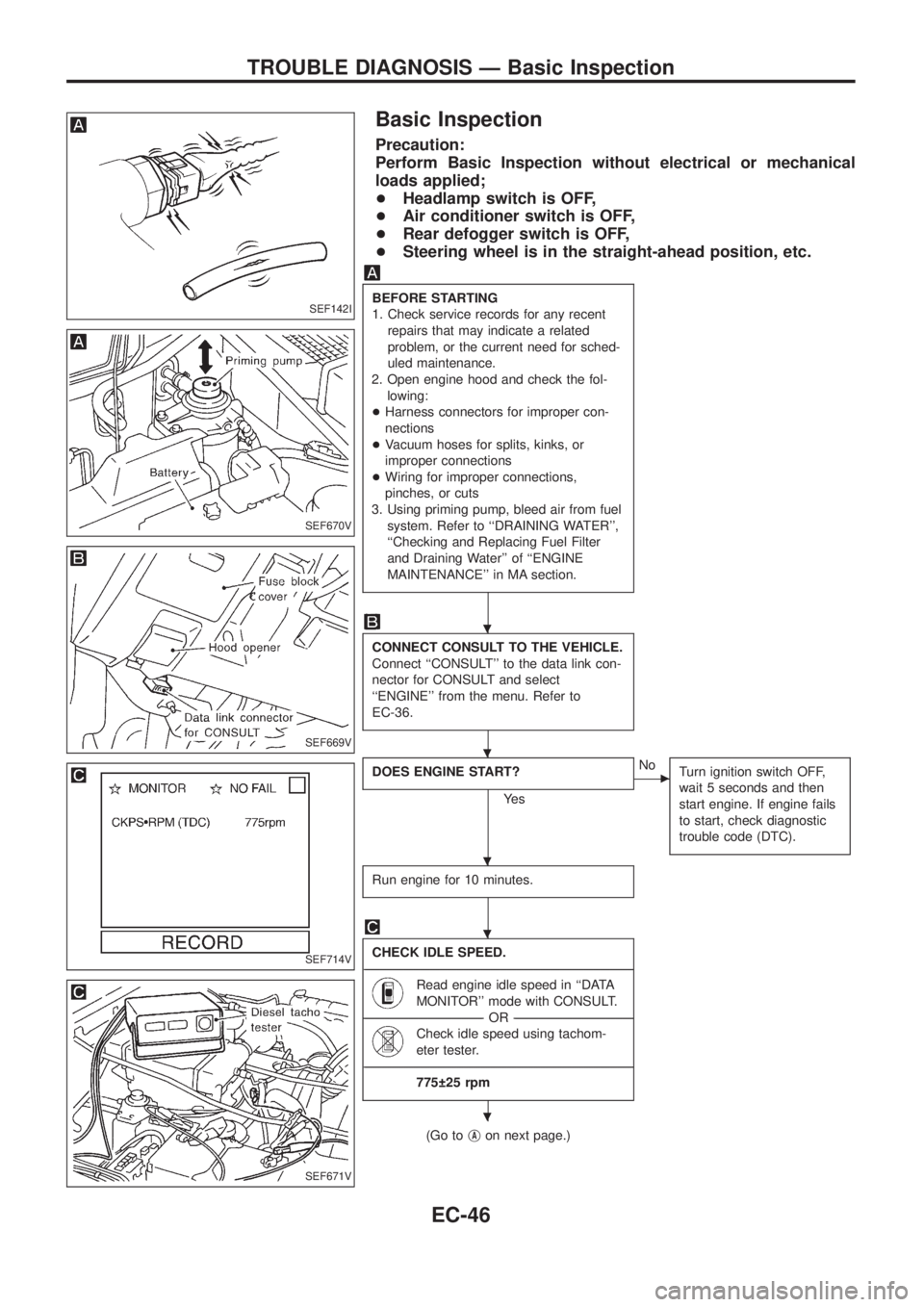
Basic Inspection
Precaution:
Perform Basic Inspection without electrical or mechanical
loads applied;
+Headlamp switch is OFF,
+Air conditioner switch is OFF,
+Rear defogger switch is OFF,
+Steering wheel is in the straight-ahead position, etc.
BEFORE STARTING
1. Check service records for any recent
repairs that may indicate a related
problem, or the current need for sched-
uled maintenance.
2. Open engine hood and check the fol-
lowing:
+Harness connectors for improper con-
nections
+Vacuum hoses for splits, kinks, or
improper connections
+Wiring for improper connections,
pinches, or cuts
3. Using priming pump, bleed air from fuel
system. Refer to ``DRAINING WATER'',
``Checking and Replacing Fuel Filter
and Draining Water'' of ``ENGINE
MAINTENANCE'' in MA section.
CONNECT CONSULT TO THE VEHICLE.
Connect ``CONSULT'' to the data link con-
nector for CONSULT and select
``ENGINE'' from the menu. Refer to
EC-36.
DOES ENGINE START?
Ye s
cNo
Turn ignition switch OFF,
wait 5 seconds and then
start engine. If engine fails
to start, check diagnostic
trouble code (DTC).
Run engine for 10 minutes.
CHECK IDLE SPEED.
----------------------------------------------------------------------------------------------------------------------------------------------------------------------------------------------------------------------------------------------------------------------------------------------------------------
Read engine idle speed in ``DATA
MONITOR'' mode with CONSULT.
--------------------------------------------------------------------------------------------------------------------------------------OR--------------------------------------------------------------------------------------------------------------------------------------
Check idle speed using tachom-
eter tester.
----------------------------------------------------------------------------------------------------------------------------------------------------------------------------------------------------------------------------------------------------------------------------------------------------------------
775 25 rpm
(Go tojAon next page.)
SEF142I
SEF670V
SEF669V
SEF714V
SEF671V
.
.
.
.
.
TROUBLE DIAGNOSIS Ð Basic Inspection
EC-46