Page 204 of 1226
Major Sensor Reference Graph in Data Monitor
Mode
The following are the major sensor reference graphs in ``DATA MONITOR'' mode.
(Select ``HI SPEED'' in ``DATA MONITOR'' with CONSULT.)
ACCEL POS SEN, C/SLEEV POS/S, ACT INJ TIMG
Below is the data for ``ACCEL POS SEN'', ``C/SLEEV POS/S'' and ``ACT INJ TIMG'' when revving engine
quickly up to 3,000 rpm under no load after warming up engine sufficiently.
Each value is for reference, the exact value may vary.
SEF663S
TROUBLE DIAGNOSIS Ð General Description
EC-53
Page 206 of 1226
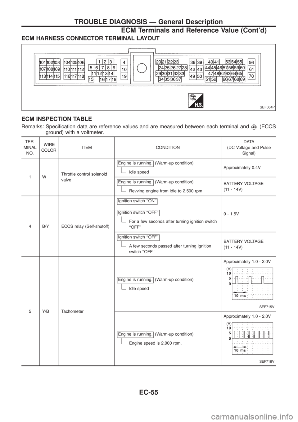
ECM HARNESS CONNECTOR TERMINAL LAYOUT
ECM INSPECTION TABLE
Remarks: Speci®cation data are reference values and are measured between each terminal andV43(ECCS
ground) with a voltmeter.
TER-
MINAL
NO.WIRE
COLORITEM CONDITIONDATA
(DC Voltage and Pulse
Signal)
1WThrottle control solenoid
valveEngine is running.
(Warm-up condition)
Idle speedApproximately 0.4V
Engine is running.
(Warm-up condition)
Revving engine from idle to 2,500 rpmBATTERY VOLTAGE
(11 - 14V)
4 B/Y ECCS relay (Self-shutoff)Ignition switch ``ON''
Ignition switch ``OFF''
For a few seconds after turning ignition switch
``OFF''0 - 1.5V
Ignition switch ``OFF''
A few seconds passed after turning ignition
switch ``OFF''BATTERY VOLTAGE
(11 - 14V)
5 Y/B TachometerEngine is running.
(Warm-up condition)
Idle speedApproximately 1.0 - 2.0V
SEF715V
Engine is running.(Warm-up condition)
Engine speed is 2,000 rpm.Approximately 1.0 - 2.0V
SEF716V
SEF064P
TROUBLE DIAGNOSIS Ð General Description
ECM Terminals and Reference Value (Cont'd)
EC-55
Page 207 of 1226
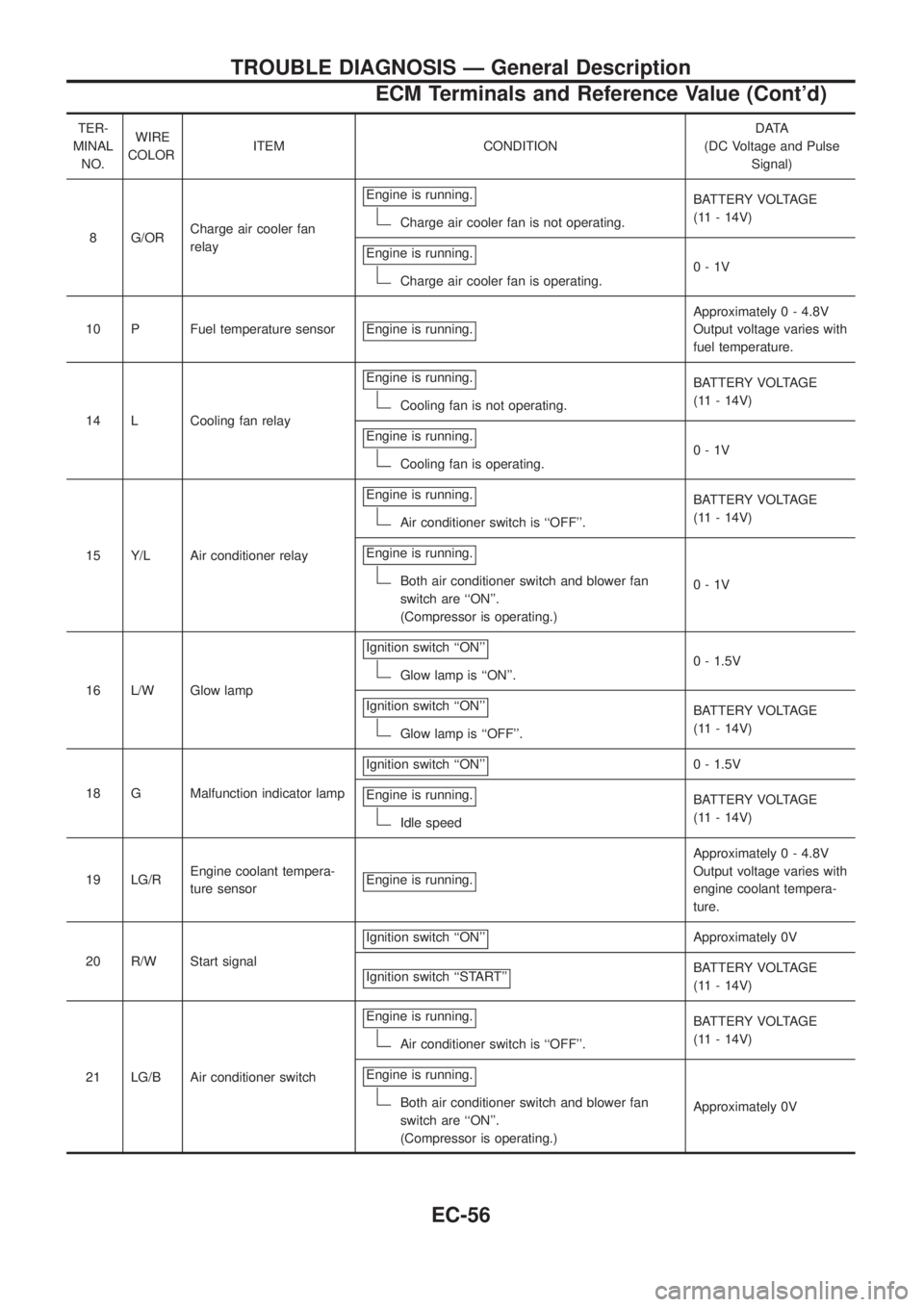
TER-
MINAL
NO.WIRE
COLORITEM CONDITIONDATA
(DC Voltage and Pulse
Signal)
8 G/ORCharge air cooler fan
relayEngine is running.
Charge air cooler fan is not operating.BATTERY VOLTAGE
(11 - 14V)
Engine is running.
Charge air cooler fan is operating.0-1V
10 P Fuel temperature sensor Engine is running.
Approximately 0 - 4.8V
Output voltage varies with
fuel temperature.
14 L Cooling fan relayEngine is running.
Cooling fan is not operating.BATTERY VOLTAGE
(11 - 14V)
Engine is running.
Cooling fan is operating.0-1V
15 Y/L Air conditioner relayEngine is running.
Air conditioner switch is ``OFF''.BATTERY VOLTAGE
(11 - 14V)
Engine is running.
Both air conditioner switch and blower fan
switch are ``ON''.
(Compressor is operating.)0-1V
16 L/W Glow lampIgnition switch ``ON''
Glow lamp is ``ON''.0 - 1.5V
Ignition switch ``ON''
Glow lamp is ``OFF''.BATTERY VOLTAGE
(11 - 14V)
18 G Malfunction indicator lampIgnition switch ``ON''
0 - 1.5V
Engine is running.
Idle speedBATTERY VOLTAGE
(11 - 14V)
19 LG/REngine coolant tempera-
ture sensorEngine is running.
Approximately 0 - 4.8V
Output voltage varies with
engine coolant tempera-
ture.
20 R/W Start signalIgnition switch ``ON''
Approximately 0V
Ignition switch ``START''
BATTERY VOLTAGE
(11 - 14V)
21 LG/B Air conditioner switchEngine is running.
Air conditioner switch is ``OFF''.BATTERY VOLTAGE
(11 - 14V)
Engine is running.
Both air conditioner switch and blower fan
switch are ``ON''.
(Compressor is operating.)Approximately 0V
TROUBLE DIAGNOSIS Ð General Description
ECM Terminals and Reference Value (Cont'd)
EC-56
Page 208 of 1226
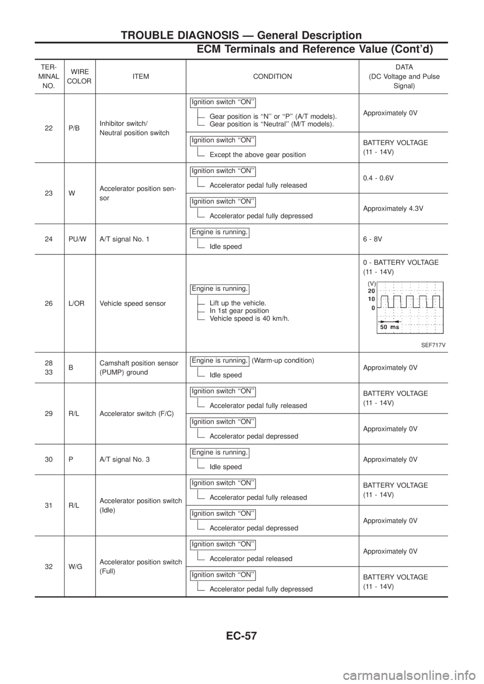
TER-
MINAL
NO.WIRE
COLORITEM CONDITIONDATA
(DC Voltage and Pulse
Signal)
22 P/BInhibitor switch/
Neutral position switchIgnition switch ``ON''
Gear position is ``N'' or ``P'' (A/T models).Gear position is ``Neutral'' (M/T models).Approximately 0V
Ignition switch ``ON''
Except the above gear positionBATTERY VOLTAGE
(11 - 14V)
23 WAccelerator position sen-
sorIgnition switch ``ON''
Accelerator pedal fully released0.4 - 0.6V
Ignition switch ``ON''
Accelerator pedal fully depressedApproximately 4.3V
24 PU/W A/T signal No. 1Engine is running.
Idle speed6-8V
26 L/OR Vehicle speed sensorEngine is running.
Lift up the vehicle.In 1st gear positionVehicle speed is 40 km/h.0 - BATTERY VOLTAGE
(11 - 14V)
SEF717V
28
33BCamshaft position sensor
(PUMP) groundEngine is running.(Warm-up condition)
Idle speedApproximately 0V
29 R/L Accelerator switch (F/C)Ignition switch ``ON''
Accelerator pedal fully releasedBATTERY VOLTAGE
(11 - 14V)
Ignition switch ``ON''
Accelerator pedal depressedApproximately 0V
30 P A/T signal No. 3Engine is running.
Idle speedApproximately 0V
31 R/LAccelerator position switch
(Idle)Ignition switch ``ON''
Accelerator pedal fully releasedBATTERY VOLTAGE
(11 - 14V)
Ignition switch ``ON''
Accelerator pedal depressedApproximately 0V
32 W/GAccelerator position switch
(Full)Ignition switch ``ON''
Accelerator pedal releasedApproximately 0V
Ignition switch ``ON''
Accelerator pedal fully depressedBATTERY VOLTAGE
(11 - 14V)
TROUBLE DIAGNOSIS Ð General Description
ECM Terminals and Reference Value (Cont'd)
EC-57
Page 209 of 1226
TER-
MINAL
NO.WIRE
COLORITEM CONDITIONDATA
(DC Voltage and Pulse
Signal)
34 W Needle lift sensorEngine is running.
(Warm-up condition)
Idle speedApproximately 0V
SEF718V
Engine is running.(Warm-up condition)
Engine speed is 2,000 rpm.Approximately 0V
SEF719V
35 R Mass air ¯ow sensorEngine is running.(Warm-up condition)
Idle speed1.6 - 2.0V
36 LGCharge air temperature
sensorEngine is running.
Approximately 0 - 4.8V
Output voltage varies with
charge air temperature.
37 P/B A/T signal No. 2Engine is running.
Idle speed6-8V
38 B/Y Ignition switchIgnition switch ``OFF''
0V
Ignition switch ``ON''
BATTERY VOLTAGE
(11 - 14V)
39
43B ECCS groundEngine is running.
Idle speedEngine ground
(Probe this terminal with
@tester probe when
measuring.)
TROUBLE DIAGNOSIS Ð General Description
ECM Terminals and Reference Value (Cont'd)
EC-58
Page 210 of 1226
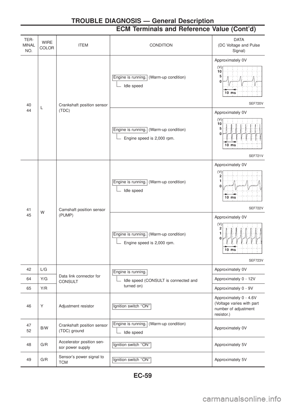
TER-
MINAL
NO.WIRE
COLORITEM CONDITIONDATA
(DC Voltage and Pulse
Signal)
40
44LCrankshaft position sensor
(TDC)Engine is running.
(Warm-up condition)
Idle speedApproximately 0V
SEF720V
Engine is running.(Warm-up condition)
Engine speed is 2,000 rpm.Approximately 0V
SEF721V
41
45WCamshaft position sensor
(PUMP)Engine is running.
(Warm-up condition)
Idle speedApproximately 0V
SEF722V
Engine is running.(Warm-up condition)
Engine speed is 2,000 rpm.Approximately 0V
SEF723V
42 L/G
Data link connector for
CONSULTEngine is running.
Idle speed (CONSULT is connected and
turned on)Approximately 0V
64 Y/GApproximately0-12V
65 Y/RApproximately0-9V
46 Y Adjustment resistor Ignition switch ``ON''
Approximately 0 - 4.6V
(Voltage varies with part
number of adjustment
resistor.)
47
52B/WCrankshaft position sensor
(TDC) groundEngine is running.
(Warm-up condition)
Idle speedApproximately 0V
48 G/RAccelerator position sen-
sor power supplyIgnition switch ``ON''
Approximately 5V
49 G/RSensor's power signal to
TCMIgnition switch ``ON''
Approximately 5V
TROUBLE DIAGNOSIS Ð General Description
ECM Terminals and Reference Value (Cont'd)
EC-59
Page 211 of 1226
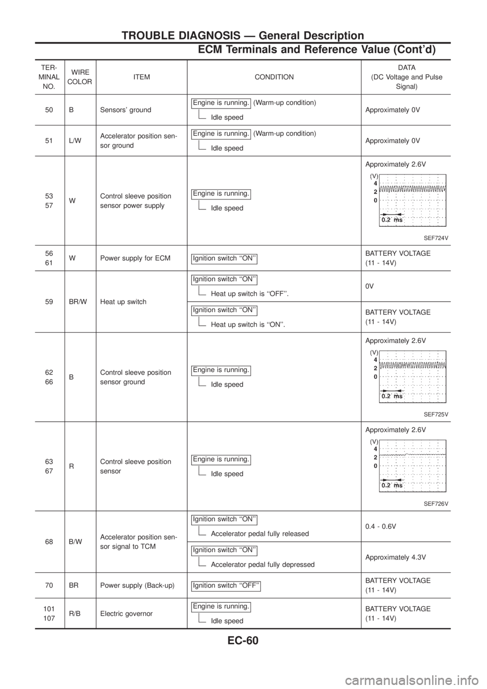
TER-
MINAL
NO.WIRE
COLORITEM CONDITIONDATA
(DC Voltage and Pulse
Signal)
50 B Sensors' groundEngine is running.
(Warm-up condition)
Idle speedApproximately 0V
51 L/WAccelerator position sen-
sor groundEngine is running.
(Warm-up condition)
Idle speedApproximately 0V
53
57WControl sleeve position
sensor power supplyEngine is running.
Idle speedApproximately 2.6V
SEF724V
56
61W Power supply for ECM Ignition switch ``ON''BATTERY VOLTAGE
(11 - 14V)
59 BR/W Heat up switchIgnition switch ``ON''
Heat up switch is ``OFF''.0V
Ignition switch ``ON''
Heat up switch is ``ON''.BATTERY VOLTAGE
(11 - 14V)
62
66BControl sleeve position
sensor groundEngine is running.
Idle speedApproximately 2.6V
SEF725V
63
67RControl sleeve position
sensorEngine is running.
Idle speedApproximately 2.6V
SEF726V
68 B/WAccelerator position sen-
sor signal to TCMIgnition switch ``ON''Accelerator pedal fully released0.4 - 0.6V
Ignition switch ``ON''
Accelerator pedal fully depressedApproximately 4.3V
70 BR Power supply (Back-up) Ignition switch ``OFF''
BATTERY VOLTAGE
(11 - 14V)
101
107R/B Electric governorEngine is running.
Idle speedBATTERY VOLTAGE
(11 - 14V)
TROUBLE DIAGNOSIS Ð General Description
ECM Terminals and Reference Value (Cont'd)
EC-60
Page 212 of 1226
TER-
MINAL
NO.WIRE
COLORITEM CONDITIONDATA
(DC Voltage and Pulse
Signal)
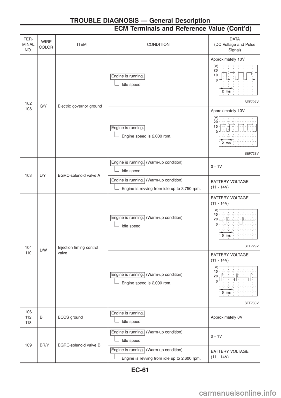
102
108G/Y Electric governor groundEngine is running.
Idle speedApproximately 10V
SEF727V
Engine is running.
Engine speed is 2,000 rpm.Approximately 10V
SEF728V
103 L/Y EGRC-solenoid valve AEngine is running.
(Warm-up condition)
Idle speed0-1V
Engine is running.
(Warm-up condition)
Engine is revving from idle up to 3,750 rpm.BATTERY VOLTAGE
(11 - 14V)
104
11 0L/WInjection timing control
valveEngine is running.
(Warm-up condition)
Idle speedBATTERY VOLTAGE
(11 - 14V)
SEF729V
Engine is running.(Warm-up condition)
Engine speed is 2,000 rpm.BATTERY VOLTAGE
(11 - 14V)
SEF730V
106
11 2
11 8B ECCS groundEngine is running.
Idle speedApproximately 0V
109 BR/Y EGRC-solenoid valve BEngine is running.
(Warm-up condition)
Idle speed0-1V
Engine is running.
(Warm-up condition)
Engine is revving from idle up to 2,600 rpm.BATTERY VOLTAGE
(11 - 14V)
TROUBLE DIAGNOSIS Ð General Description
ECM Terminals and Reference Value (Cont'd)
EC-61