Page 169 of 1226

Fuel Injection Timing System
SYSTEM DESCRIPTION
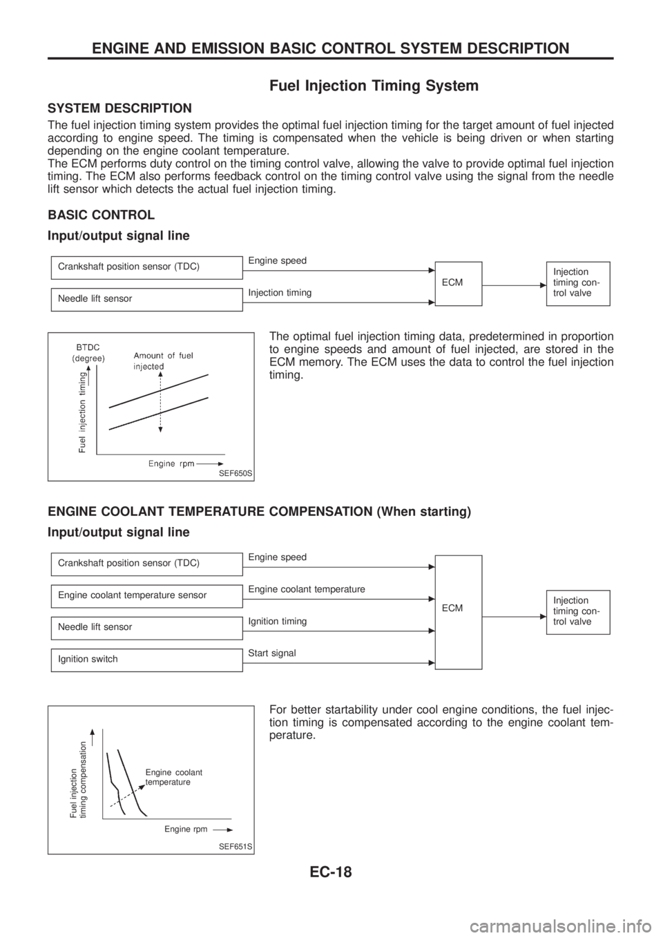
The fuel injection timing system provides the optimal fuel injection timing for the target amount of fuel injected
according to engine speed. The timing is compensated when the vehicle is being driven or when starting
depending on the engine coolant temperature.
The ECM performs duty control on the timing control valve, allowing the valve to provide optimal fuel injection
timing. The ECM also performs feedback control on the timing control valve using the signal from the needle
lift sensor which detects the actual fuel injection timing.
BASIC CONTROL
Input/output signal line
Crankshaft position sensor (TDC)cEngine speed
ECM
c
Injection
timing con-
trol valve
Needle lift sensorcInjection timing
The optimal fuel injection timing data, predetermined in proportion
to engine speeds and amount of fuel injected, are stored in the
ECM memory. The ECM uses the data to control the fuel injection
timing.
ENGINE COOLANT TEMPERATURE COMPENSATION (When starting)
Input/output signal line
Crankshaft position sensor (TDC)cEngine speed
ECM
c
Injection
timing con-
trol valveEngine coolant temperature sensorcEngine coolant temperature
Needle lift sensor
cIgnition timing
Ignition switch
cStart signal
For better startability under cool engine conditions, the fuel injec-
tion timing is compensated according to the engine coolant tem-
perature.
SEF650S
SEF651S
Fuel injection
timing compensation
Engine coolant
temperature
Engine rpm
ENGINE AND EMISSION BASIC CONTROL SYSTEM DESCRIPTION
EC-18
Page 170 of 1226

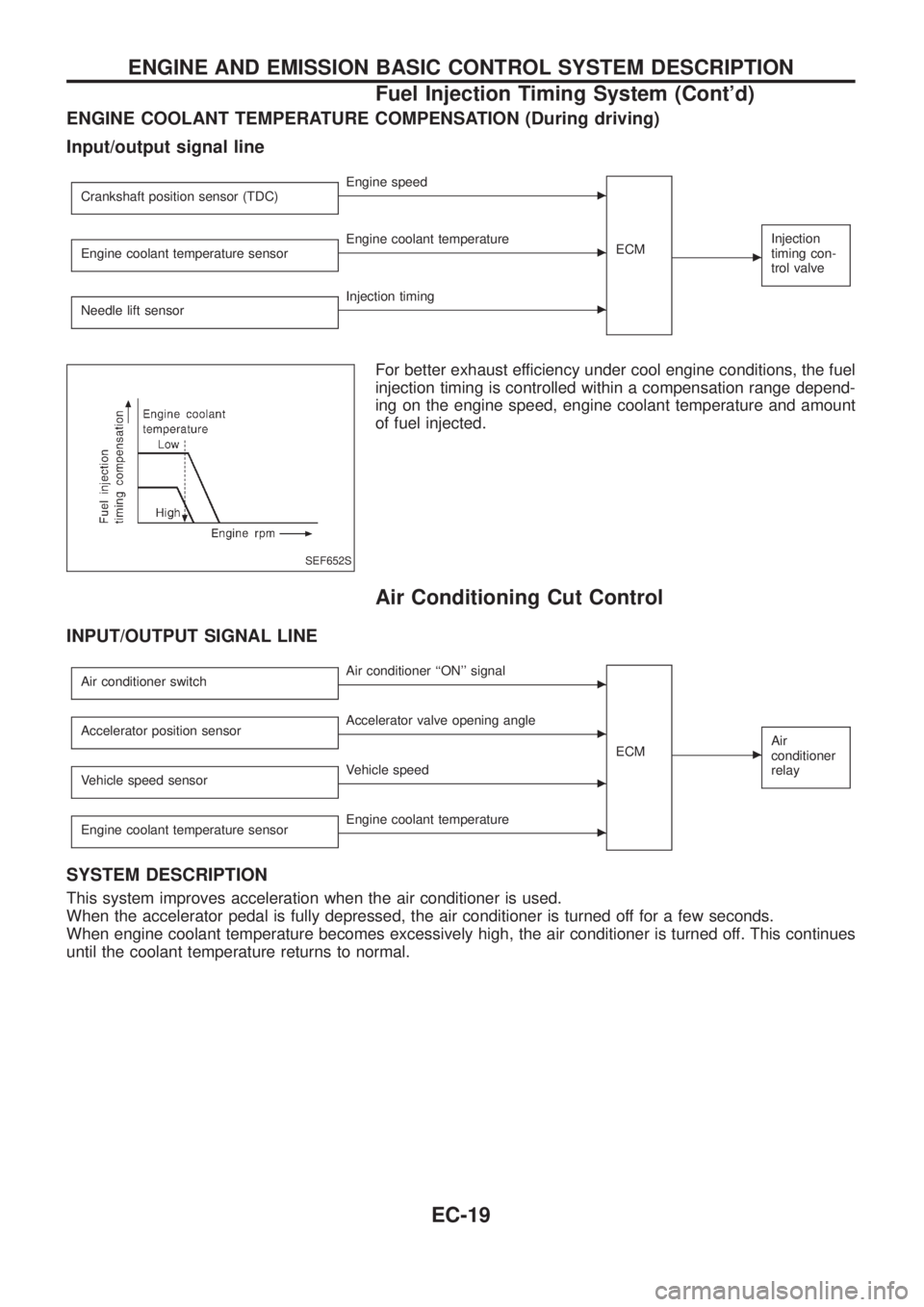
ENGINE COOLANT TEMPERATURE COMPENSATION (During driving)
Input/output signal line
Crankshaft position sensor (TDC)cEngine speed
ECM
c
Injection
timing con-
trol valveEngine coolant temperature sensorcEngine coolant temperature
Needle lift sensor
cInjection timing
For better exhaust efficiency under cool engine conditions, the fuel
injection timing is controlled within a compensation range depend-
ing on the engine speed, engine coolant temperature and amount
of fuel injected.
Air Conditioning Cut Control
INPUT/OUTPUT SIGNAL LINE
Air conditioner switchcAir conditioner ``ON'' signal
ECM
cAir
conditioner
relayAccelerator position sensorcAccelerator valve opening angle
Vehicle speed sensor
cVehicle speed
Engine coolant temperature sensor
cEngine coolant temperature
SYSTEM DESCRIPTION
This system improves acceleration when the air conditioner is used.
When the accelerator pedal is fully depressed, the air conditioner is turned off for a few seconds.
When engine coolant temperature becomes excessively high, the air conditioner is turned off. This continues
until the coolant temperature returns to normal.
SEF652S
ENGINE AND EMISSION BASIC CONTROL SYSTEM DESCRIPTION
Fuel Injection Timing System (Cont'd)
EC-19
Page 171 of 1226
Fuel Cut Control (at no load & high engine
speed)
INPUT/OUTPUT SIGNAL LINE
Vehicle speed sensorcVehicle speed
ECM
cElectric
governor
Neutral position switchcNeutral position
Accelerator position switch or Accelerator
switch (F/C)
cAccelerator position
Engine coolant temperature sensor
cEngine coolant temperature
Crankshaft position sensor (TDC)
cEngine speed
If the engine speed is above 3,000 rpm with no load (for example,
in neutral and engine speed over 3,000 rpm) fuel will be cut off after
some time. The exact time when the fuel is cut off varies based on
engine speed.
Fuel cut will operate until the engine speed reaches 1,500 rpm,
then fuel cut is cancelled.
NOTE:
This function is different from deceleration control and fuel cut
solenoid valve control listed under ``Fuel Injection System'',
EC-15 and ``TROUBLE DIAGNOSIS FOR DTC 36, 37, 38'',
EC-130.
ENGINE AND EMISSION BASIC CONTROL SYSTEM DESCRIPTION
EC-20
Page 173 of 1226

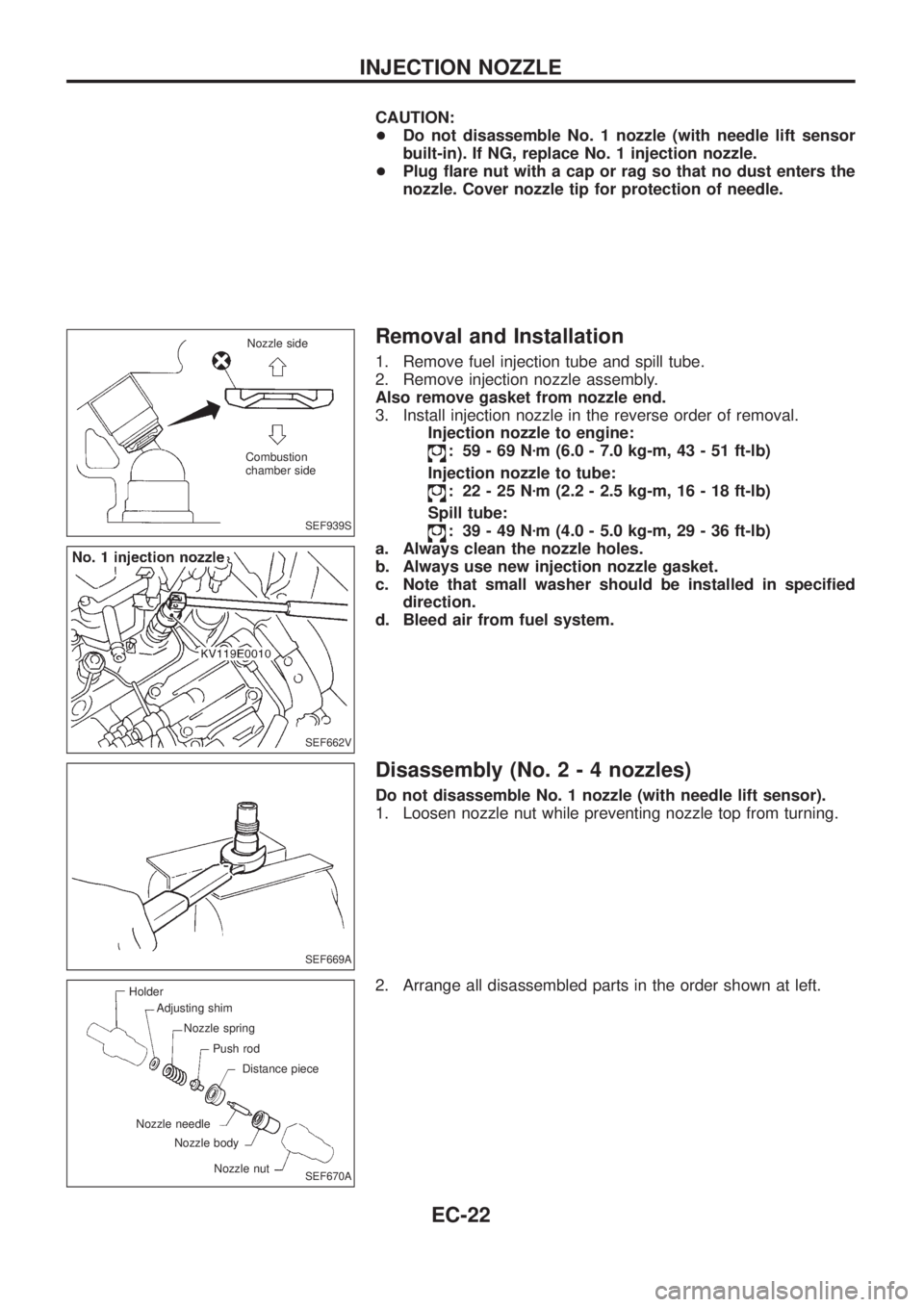
CAUTION:
+Do not disassemble No. 1 nozzle (with needle lift sensor
built-in). If NG, replace No. 1 injection nozzle.
+Plug ¯are nut with a cap or rag so that no dust enters the
nozzle. Cover nozzle tip for protection of needle.
Removal and Installation
1. Remove fuel injection tube and spill tube.
2. Remove injection nozzle assembly.
Also remove gasket from nozzle end.
3. Install injection nozzle in the reverse order of removal.
Injection nozzle to engine:
: 59-69Nzm (6.0 - 7.0 kg-m, 43 - 51 ft-lb)
Injection nozzle to tube:
: 22-25Nzm (2.2 - 2.5 kg-m, 16 - 18 ft-lb)
Spill tube:
: 39-49Nzm (4.0 - 5.0 kg-m, 29 - 36 ft-lb)
a. Always clean the nozzle holes.
b. Always use new injection nozzle gasket.
c. Note that small washer should be installed in speci®ed
direction.
d. Bleed air from fuel system.
Disassembly (No.2-4nozzles)
Do not disassemble No. 1 nozzle (with needle lift sensor).
1. Loosen nozzle nut while preventing nozzle top from turning.
2. Arrange all disassembled parts in the order shown at left.
SEF939S
Nozzle side
Combustion
chamber side
SEF662V
SEF669A
SEF670A
Holder
Adjusting shim
Nozzle spring
Push rod
Distance piece
Nozzle nut Nozzle body Nozzle needle
INJECTION NOZZLE
EC-22
Page 181 of 1226

DTC and MIL Detection Logic
When a malfunction is detected for the ®rst time, the malfunction (DTC) is stored in the ECM memory.
The MIL will light up each time the ECM detects malfunction. However, if the same malfunction is experienced
in two consecutive driving patterns and the engine is still running, the MIL will stay lit up. For diagnostic items
causing the MIL to light up, refer to ``DIAGNOSTIC TROUBLE CODE INDEX'', EC-1.
Diagnostic Trouble Code (DTC)
HOW TO READ DTC
The diagnostic trouble code can be read by the following methods.
1. The number of blinks of the malfunction indicator lamp in the Diagnostic Test Mode II (Self-Diagnostic
Results) Examples: 11, 13, 14, etc.
These DTCs are controlled by NISSAN.
2. CONSULT Examples: ``CAM POS SEN (PUMP)'', etc.
+Output of the trouble code means that the indicated circuit has a malfunction. However, in the Mode
II it does not indicate whether the malfunction is still occurring or occurred in the past and returned
to normal.
CONSULT can identify them. Therefore, using CONSULT (if available) is recommended.
HOW TO ERASE DTC
The diagnostic trouble code can be erased by the following methods.
Selecting ``ERASE'' in the ``SELF-DIAG RESULTS'' mode with CONSULT.
Changing the diagnostic test mode from Diagnostic Test Mode II to Mode I. (Refer to EC-32.)
+If the battery terminal is disconnected, the diagnostic trouble code will be lost within 24 hours.
+When you erase the DTC, using CONSULT is easier and quicker than switching the diagnostic test
modes.
HOW TO ERASE DTC (With CONSULT)
1. If the ignition switch stays ``ON'' after repair work, be sure to turn ignition switch ``OFF'' once. Wait at least
5 seconds and then turn it ``ON'' (Engine stopped) again.
2. Turn CONSULT ``ON'' and touch ``ENGINE''.
3. Touch ``SELF-DIAG RESULTS''.
4. Touch ``ERASE''. (The DTC in the ECM will be erased.)
HOW TO ERASE DTC (No Tools)
1. If the ignition switch stays ``ON'' after repair work, be sure to turn ignition switch ``OFF'' once. Wait at least
5 seconds and then turn it ``ON'' again.
2. Change the diagnostic test mode from Mode II to Mode I. (Refer to EC-32.)
SEF691S
ON BOARD DIAGNOSTIC SYSTEM DESCRIPTION
EC-30
Page 182 of 1226

Malfunction Indicator Lamp (MIL)
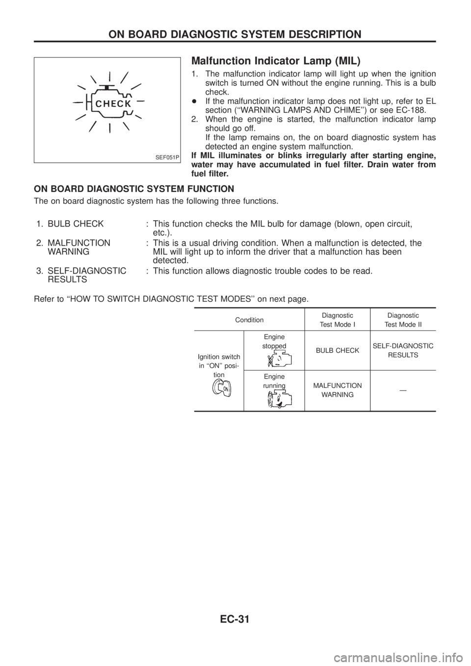
1. The malfunction indicator lamp will light up when the ignition
switch is turned ON without the engine running. This is a bulb
check.
+If the malfunction indicator lamp does not light up, refer to EL
section (``WARNING LAMPS AND CHIME'') or see EC-188.
2. When the engine is started, the malfunction indicator lamp
should go off.
If the lamp remains on, the on board diagnostic system has
detected an engine system malfunction.
If MIL illuminates or blinks irregularly after starting engine,
water may have accumulated in fuel ®lter. Drain water from
fuel ®lter.
ON BOARD DIAGNOSTIC SYSTEM FUNCTION
The on board diagnostic system has the following three functions.
1. BULB CHECK : This function checks the MIL bulb for damage (blown, open circuit,
etc.).
2. MALFUNCTION
WARNING: This is a usual driving condition. When a malfunction is detected, the
MIL will light up to inform the driver that a malfunction has been
detected.
3. SELF-DIAGNOSTIC
RESULTS: This function allows diagnostic trouble codes to be read.
Refer to ``HOW TO SWITCH DIAGNOSTIC TEST MODES'' on next page.
ConditionDiagnostic
Test Mode IDiagnostic
Test Mode II
Ignition switch
in ``ON'' posi-
tion
Engine
stopped
BULB CHECKSELF-DIAGNOSTIC
RESULTS
Engine
running
MALFUNCTION
WARNINGÐ
SEF051P
ON BOARD DIAGNOSTIC SYSTEM DESCRIPTION
EC-31
Page 183 of 1226
HOW TO SWITCH DIAGNOSTIC TEST MODES
Turn ignition switch ``ON''.
(Do not start engine.)
c
Diagnostic Test Mode I Ð BULB CHECK.
Refer to previous page.
MIL should come on.
.
OK
cNG
Check MIL circuit.
(See EC-188.)
OK
.
cNG
Repair harness or
connectors.
OK
b
cG
Start engine.
cDiagnostic Test
Mode I
Ð MALFUNC-
TION WARN-
ING.
Refer to previ-
ous page.
Data link connector for CONSULT
(Connect CHK and IGN terminals with a suitable
harness.)
MIL should go off.
cNG
Check MIL circuit and data link connector for
CONSULT circuit. (See EC-188.)
OK
.
NG
Repair harness or
connectors.
OK
Wait at least 2 seconds.
.b
Data link connector for CONSULT
(Disconnect the suitable harness between CHK
and IGN terminals.)
DIAGNOSTIC TEST MODE II
Ð SELF-DIAGNOSTIC RESULTS
.jBjA
.
.
.
.
ON BOARD DIAGNOSTIC SYSTEM DESCRIPTION
Malfunction Indicator Lamp (MIL) (Cont'd)
EC-32
Page 184 of 1226
jB
m
jA
Data link connector for CONSULT
(Connect CHK and IGN terminals with a suit-
able harness.)
Wait at least 2 seconds.
Data link connector for CONSULT
(Disconnect the suitable harness between
CHK and IGN terminals.)
If the suitable harness is disconnected at this
time, the diagnostic trouble code will be
erased from the backup memory in the ECM.
+Switching the modes is not possible when the engine
is running.
+When ignition switch is turned off during diagnosis,
power to ECM will drop after approx. 5 seconds.
The diagnosis will automatically return to Diagnostic
Test Mode I..
.
.
.
ON BOARD DIAGNOSTIC SYSTEM DESCRIPTION
Malfunction Indicator Lamp (MIL) (Cont'd)
EC-33