Page 77 of 1226

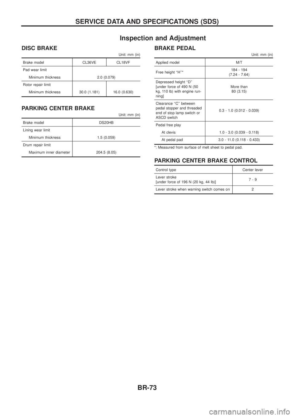
Inspection and Adjustment
DISC BRAKE
Unit: mm (in)
Brake model CL36VE CL18VF
Pad wear limit
Minimum thickness 2.0 (0.079)
Rotor repair limit
Minimum thickness 30.0 (1.181) 16.0 (0.630)
PARKING CENTER BRAKE
Unit: mm (in)
Brake model DS20HB
Lining wear limit
Minimum thickness 1.5 (0.059)
Drum repair limit
Maximum inner diameter 204.5 (8.05)
BRAKE PEDAL
Unit: mm (in)
Applied model M/T
Free height ``H''*184 - 194
(7.24 - 7.64)
Depressed height ``D''
[under force of 490 N (50
kg, 110 lb) with engine run-
ning]More than
80 (3.15)
Clearance ``C'' between
pedal stopper and threaded
end of stop lamp switch or
ASCD switch0.3 - 1.0 (0.012 - 0.039)
Pedal free play
At clevis 1.0 - 3.0 (0.039 - 0.118)
At pedal pad 3.0 - 11.0 (0.118 - 0.433)
*: Measured from surface of melt sheet to pedal pad.
PARKING CENTER BRAKE CONTROL
Control type Center lever
Lever stroke
[under force of 196 N (20 kg, 44 lb)]7-9
Lever stroke when warning switch comes on 2
SERVICE DATA AND SPECIFICATIONS (SDS)
BR-73
Page 78 of 1226

BODY & TRIM
SECTION
BT
CONTENTS
PRECAUTIONS ...............................................................1
Service Notice..............................................................1
Supplemental Restraint System (SRS) ``AIR
BAG''and``SEATBELTPRE-TENSIONER''...............1
GENERAL SERVICING ...................................................2
Clip and Fastener ........................................................2
BODY END ......................................................................4
Body Front End............................................................4
Body Rear End and Opener ........................................6
DOOR ........................................................................\
.......9
Front Door....................................................................9
Rear Door ..................................................................10
INSTRUMENT PANEL ................................................... 11
INTERIOR TRIM ............................................................14
Side and Floor Trim ...................................................14
Door Trim ...................................................................18
Roof Trim ...................................................................20
Back Door Trim ..........................................................24 EXTERIOR
.....................................................................26
SEAT ........................................................................\
......32
Front Seat ..................................................................32
Heated Seat ...............................................................34
Rear Seat...................................................................35
3rd Seat .....................................................................37
SUNROOF ......................................................................39
WINDSHIELD AND WINDOWS ....................................42
Windshield .................................................................43
Rear Side Window .....................................................44
Back Door Window ....................................................45
MIRROR ........................................................................\
.46
Door Mirror.................................................................46
CAB BODY ....................................................................47
Body Mounting ...........................................................48
BODY ALIGNMENT .......................................................49
Engine Compartment .................................................49
Underbody .................................................................51
. For seat belt, refer to MA and RS section.
. For wiring diagrams of body electrical systems, refer to EL section.
BT
Page 82 of 1226

Body Front End
+When removing or installing hood, place a cloth or other padding on front fender panel and cowl top. This
prevents vehicle body from being scratched.
+Bumper fascia is made of plastic. Do not use excessive force and be sure to keep oil away from it.
+Hood adjustment: Adjust at hinge portion.
+Hood lock adjustment: After adjusting, check hood lock control operation. Apply a coat of grease to hood
locks engaging mechanism.
+Hood opener: Do not attempt to bend cable forcibly. Doing so increases effort required to unlock hood.
REMOVAL Ð Front bumper assembly
V1Remove front guard bar. Refer to ``EXTERIOR'' for details, BT-26.
V2Remove left and right headlamp wipers (on models with headlamp wipers).
V3Remove clips securing front grille and remove the front grille.
V4Remove screws and bolts securing left and right front bumper side bracket.
V5Remove bolts securing bumper lower to engine under cover.
V6Remove bolts securing left and right front bumper stay upper (without winch).
V7Remove bolts securing left and right front bumper stay side.
V8Extract bumper assembly.
SBT518
BODY END
BT-4
Page 125 of 1226
CAB BODY
+Remove following parts in engine room at least.
(1) Main harness and other wiring harness
+Disconnect brake and clutch line in engine compartment.
+Remove following parts from underbody at least.
(1) Transmission and transfer control levers
(2) Parking brake control lever and cable
(3) Main harness and other wiring harness
SBF025E
CAB BODY
BT-47
Page 127 of 1226
+All dimensions indicated in ®gures are actual ones.
+When using a tracking gauge, adjust both pointers to equal length. Then check the pointers and gauge
itself to make sure there is no free play.
+When a measuring tape is used, check to be sure there is no elongation, twisting or bending.
+Measurements should be taken at the center of the mounting holes.
+An asterisk (*) following the value at the measuring point indicates that the measuring point on the other
side is symmetrically the same value.
+The coordinates of the measurement points are the distances measured from the standard line of ``X'', ``Y''
and ``Z''.
Engine Compartment
MEASUREMENT
SBF874GD
SBT560
BODY ALIGNMENT
BT-49
Page 128 of 1226
MEASUREMENT POINTS
Unit: mm
SBT561
BODY ALIGNMENT
Engine Compartment (Cont'd)
BT-50
Page 136 of 1226

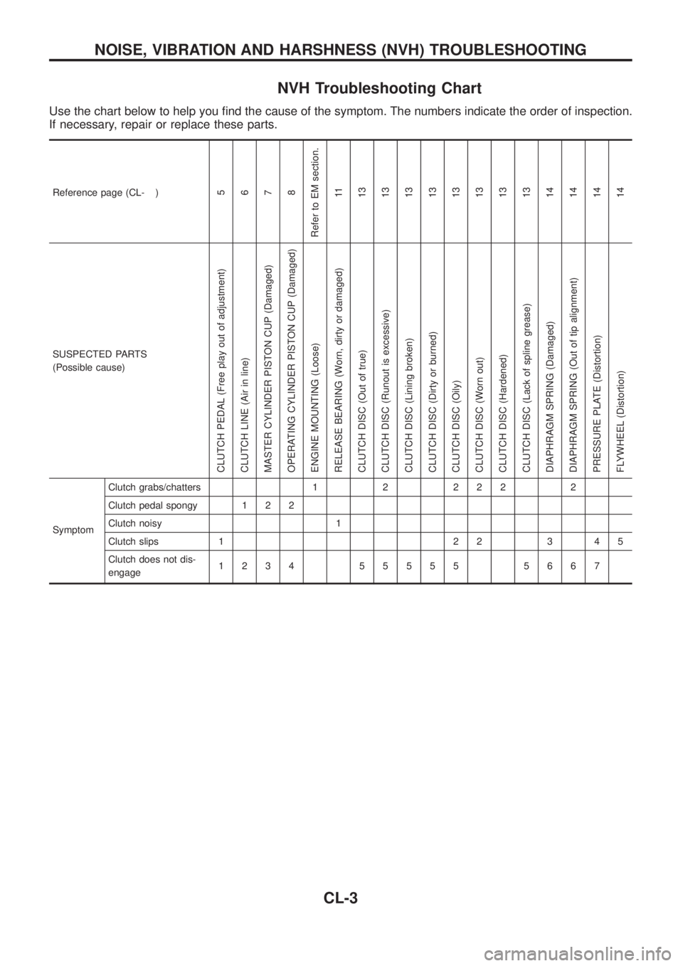
NVH Troubleshooting Chart
Use the chart below to help you ®nd the cause of the symptom. The numbers indicate the order of inspection.
If necessary, repair or replace these parts.
Reference page (CL- )5
6
7
8
Refer to EM section.
11
13
13
13
13
13
13
13
13
14
14
14
14
SUSPECTED PARTS
(Possible cause)
CLUTCH PEDAL (Free play out of adjustment)
CLUTCH LINE (Air in line)
MASTER CYLINDER PISTON CUP (Damaged)
OPERATING CYLINDER PISTON CUP (Damaged)
ENGINE MOUNTING (Loose)
RELEASE BEARING (Worn, dirty or damaged)
CLUTCH DISC (Out of true)
CLUTCH DISC (Runout is excessive)
CLUTCH DISC (Lining broken)
CLUTCH DISC (Dirty or burned)
CLUTCH DISC (Oily)
CLUTCH DISC (Worn out)
CLUTCH DISC (Hardened)
CLUTCH DISC (Lack of spline grease)
DIAPHRAGM SPRING (Damaged)
DIAPHRAGM SPRING (Out of tip alignment)
PRESSURE PLATE (Distortion)
FLYWHEEL (Distortion)
SymptomClutch grabs/chatters 1 2 2 2 2 2
Clutch pedal spongy 1 2 2
Clutch noisy 1
Clutch slips 1 2 2 3 4 5
Clutch does not dis-
engage1234 55555 5667
NOISE, VIBRATION AND HARSHNESS (NVH) TROUBLESHOOTING
CL-3
Page 142 of 1226
Clutch Booster
INSPECTION
Hoses and connectors
+Check condition of vacuum hoses and connections.
+Check vacuum hoses and check valve for air tightness.
Vacuum hose check valve
1. Remove the vacuum hose.
2. Blow air through one end (booster side) of the vacuum hose
and make sure that air passage continuity exists.
3. Blow air through the other end (engine side) of the vacuum
hose and make sure that air passage continuity does not exist.
Check valve
1. Remove the vacuum hose.
2. Check the condition of the check valve using a handy vacuum
pump.
V1V2
Vacuum pump connected to the
engine sideVacuum pump connected to the booster
side
No vacuum pressure is applied.Vacuum drop is less than 1.3 kPa (13
mbar, 10 mmHg, 0.39 inHg) at a vacuum
pressure of þ66.7 kPa (þ667 mbar, þ500
mmHg, þ19.69 inHg).
SCL772
SCL782
SCL783
HYDRAULIC CLUTCH CONTROL
CL-9