Page 1004 of 1226
Lubricating Locks, Hinges and Hood Latches
Checking Seat Belts, Buckles, Retractors,
Anchors and Adjusters
SMA994C
SMA995C
CHASSIS AND BODY MAINTENANCE
MA-27
Page 1005 of 1226
Checking Body Corrosion
Visually check the body sheet metal panel for corrosion, paint damage (scratches, chipping, rubbing, etc.) or
damage to the anti-corrosion materials. In particular, check the following locations.
Hemmed portion
Hood front end, door lower end, trunk lid rear end, etc.
Panel joint
Side sill of rear fender and center pillar, rear wheel housing of rear fender, around strut tower in engine
compartment, etc.
Panel edge
Trunk lid opening, sunroof opening, fender wheelarch ¯ange, fuel ®ller lid ¯ange, around holes in panel, etc.
Parts contact
Waist molding, windshield molding, bumper, etc.
Protectors
Damage or condition of mudguard, fender protector, chipping protector, etc.
Anti-corrosion materials
Damage or separation of anti-corrosion materials under the body.
Drain holes
Condition of drain holes at door and side sill.
When repairing corroded areas, refer to the Corrosion Repair Manual.
CHASSIS AND BODY MAINTENANCE
MA-28
Page 1006 of 1226
Engine Maintenance
INSPECTION AND ADJUSTMENT
Drive belt de¯ection
Unit: mm (in)
Drive beltsUsed belt de¯ection
De¯ection of
new belt
LimitDe¯ection
after adjust-
ment
Alternator
With air condi-
tioner compressor17 (0.67)12-14
(0.47 - 0.55)9-11
(0.35 - 0.43)
Without air condi-
tioner compressor11 (0.43)7-9
(0.28 - 0.35)6-8
(0.24 - 0.31)
Power steering oil
pump14 (0.55)10-12
(0.39 - 0.47)9-11
(0.35 - 0.43)
Applied pushing force 98 N (10 kg, 22 lb)
Engine oil capacity (Re®ll capacity)
Unit:!(Imp qt)
With oil ®lter change 6.4 (5-5/8)
Without oil ®lter change 5.8 (5-1/8)
Coolant capacity (Re®ll capacity)
With reservoir tank
Unit:!(Imp qt)
With rear heater Without rear heater
RHD 12.9 (11-3/8) 11.8 (10-3/8)
LHD 12.7 (11-1/8) 11.6 (10-1/4)
Reservoir tank 2.4 (2-1/8)
Chassis and Body Maintenance
INSPECTION AND ADJUSTMENT
Wheel balance
Maximum allowable
unbalanceDynamic
(At rim ¯ange)
g (oz)10 (0.35) (one side)
Static g (oz) 20 (0.71)
SERVICE DATA AND SPECIFICATIONS (SDS)
MA-29
Page 1010 of 1226
NVH Troubleshooting Chart
Use the chart below to help you ®nd the cause of the symptom. The numbers indicate the order of the inspec-
tion. If necessary, repair or replace these parts.
Reference page
FS5R30A
Refer to MA section (``Checking M/T Oil'',
``CHASSIS AND BODY MAINTENANCE'').
MT-9
MT-9
MT-12
MT-12
MT-10
MT-10
MT-10
MT-10
SUSPECTED PARTS (Possible cause)
Transmission model
OIL (Level low)
OIL (Wrong)
OIL (Level too high)
LIQUID GASKET (Damaged)
OIL SEAL (Worn or damaged)
CHECK PLUG RETURN SPRING AND
CHECK BALL (Worn or damaged)
SHIFT FORK (Worn)
GEAR (Worn or damaged)
BEARING (Worn or damaged)
BAULK RING (Worn or damaged)
INSERT SPRING (Damaged)
SymptomNoise 1 2 3 3
Oil leakage3122
Hard to shift or will not shift 1 1 2 2
Jumps out of gear 1 2 2
NOISE, VIBRATION AND HARSHNESS (NVH)
TROUBLESHOOTING
MT-3
Page 1103 of 1226
Removal
CAUTION:
+Before removing the rear axle, disconnect the ABS wheel
sensor from the assembly. Then move it away from the
axle. Failure to do so may result in damage to the sensor
wires and the sensor becoming inoperative.
+Wheel bearing does not require maintenance.
+If growling noise is emitted from wheel bearing during
operation, replace wheel bearing assembly.
+If the wheel bearing assembly is removed, it must be renewed.
The old assembly must not be re-used.
1. Disconnect parking brake cable and brake tube.
2. Remove nuts securing wheel bearing cage with baffle plate.
3. Draw out axle shaft with Tool.
When drawing out axle shaft, be careful not to damage oil seal.
4. Remove O-ring.
5. Remove oil seal with a screwdriver.
Do not reuse oil seal once it is removed.
Always install new one.
6. Remove ABS sensor rotor. Ð Models with ABS Ð
SRA757A
SRA845A
SRA846A
SRA799A
REAR AXLE
RA-7
Page 1122 of 1226

RESTRAINT SYSTEM
SECTION
RS
CONTENTS
PRECAUTION..................................................................1
Supplemental Restraint System (SRS) ``AIR
BAG'' and ``SEAT BELT PRE-TENSIONER''...............1
SEAT BELTS...................................................................2
Front Seat Belt.............................................................3
Rear Seat Belt .............................................................5
3rd Seat Belt ................................................................7
SUPPLEMENTAL RESTRAINT SYSTEM (SRS)............8
Precautions for SRS ``AIR BAG'' and ``Seat Belt
Pre-tensioner'' Service.................................................8
Special Service Tools ..................................................8
Description .................................................................10
SRS Component Parts Location ...............................10
Maintenance Items .................................................... 11
Removal and Installation Ð Diagnosis Sensor
Unit and Seat Belt Pre-tensioner...............................12
Removal and Installation Ð Air Bag Module and
Spiral Cable ...............................................................13
Removal Ð Air Bag Module and Spiral Cable ..........13
Removal Ð Front Passenger Air Bag Module ..........14
Installation Ð Air Bag Module and Spiral Cable .......16Installation Ð Front Passenger Air Bag Module .......16
Disposal of Air Bag Module and Seat Belt Pre-
tensioner ....................................................................17
TROUBLE DIAGNOSES Ð Supplemental
Restraint System (SRS)...............................................22
Trouble Diagnoses Introduction.................................22
How to Perform Trouble Diagnoses for Quick
and Accurate Repair ..................................................24
Schematic ..................................................................26
Wiring Diagram Ð SRS Ð ........................................27
SRS Operation Check ...............................................30
Trouble Diagnoses with CONSULT ...........................32
Trouble Diagnoses without CONSULT ......................39
Trouble Diagnoses: ``AIR BAG'' Warning Lamp
Does Not Turn Off .....................................................43
Trouble Diagnoses: ``AIR BAG'' Warning Lamp
Does Not Turn On .....................................................43
Trouble Diagnoses: SRS Does Not Enter
Diagnosis Mode Using Door Switch ..........................44
COLLISION DIAGNOSIS...............................................45
When you read wiring diagrams:
+Read GI section, ``HOW TO READ WIRING DIAGRAMS''.
+See EL section, ``POWER SUPPLY ROUTING'' for power distribution circuit.
When you perform trouble diagnoses, read GI section, ``HOW TO FOLLOW FLOW
CHART IN TROUBLE DIAGNOSES'' and ``HOW TO PERFORM EFFICIENT DIAGNOSIS
FOR AN ELECTRICAL INCIDENT''.
RS
Page 1123 of 1226

Supplemental Restraint System (SRS) ``AIR
BAG'' and ``SEAT BELT PRE-TENSIONER''
The Supplemental Restraint System such as ``AIR BAG'' and ``SEAT BELT PRE-TENSIONER'' used along with
a seat belt, helps to reduce the risk or severity of injury to the driver and front passenger in a frontal collision.
The SRS composition which is available to NISSAN MODEL Y61 is as follows (The composition varies
according to the destination.):
Driver air bag module (located in the center of the steering wheel), front passenger air bag module (located
on the instrument panel on passenger side), seat belt pre-tensioner, a diagnosis sensor unit, warning lamp,
wiring harness and spiral cable.
WARNING:
+To avoid rendering the SRS inoperative, which could increase the risk of personal injury or death
in the event of a collision which would result in air bag in¯ation, all maintenance must be performed
by an authorized NISSAN dealer.
+Improper maintenance, including incorrect removal and installation of the SRS, can lead to per-
sonal injury caused by unintentional activation of the system.
+Do not use electrical test equipment on any circuit related to the SRS unless instructed to in this
Service Manual. Spiral cable and wiring harnesses covered with yellow insulation either just before
the harness connectors or for the complete harness are related to the SRS.
PRECAUTION
RS-1
Page 1133 of 1226

Maintenance Items
CAUTION:
Do not use a circuit tester to check SRS circuit.
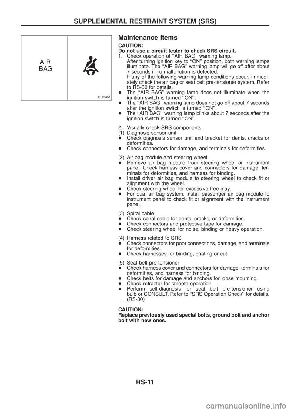
1. Check operation of ``AIR BAG'' warning lamp.
After turning ignition key to ``ON'' position, both warning lamps
illuminate. The ``AIR BAG'' warning lamp will go off after about
7 seconds if no malfunction is detected.
If any of the following warning lamp conditions occur, immedi-
ately check the air bag or seat belt pre-tensioner system. Refer
to RS-30 for details.
+The ``AIR BAG'' warning lamp does not illuminate when the
ignition switch is turned ``ON''.
+The ``AIR BAG'' warning lamp does not go off about 7 seconds
after the ignition switch is turned ``ON''.
+The ``AIR BAG'' warning lamp blinks about 7 seconds after the
ignition switch is turned ``ON''.
2. Visually check SRS components.
(1) Diagnosis sensor unit
+Check diagnosis sensor unit and bracket for dents, cracks or
deformities.
+Check connectors for damage, and terminals for deformities.
(2) Air bag module and steering wheel
+Remove air bag module from steering wheel or instrument
panel. Check harness cover and connectors for damage, ter-
minals for deformities, and harness for binding.
+Install driver air bag module to steering wheel to check ®t or
alignment with the wheel.
+Check steering wheel for excessive free play.
+For dual air bag system, install passenger air bag module to
instrument panel to check ®t or alignment with the instrument
panel.
(3) Spiral cable
+Check spiral cable for dents, cracks, or deformities.
+Check connectors and protective tape for damage.
+Check steering wheel for noise, binding or heavy operation.
(4) Harness related to SRS
+Check connectors for poor connections, damage, and terminals
for deformities.
+Check harnesses for binding, cha®ng or cut.
(5) Seat belt pre-tensioner
+Check harness cover and connectors for damage, terminals for
deformities, and harness for binding.
+Check belts for damage and anchors for loose mounting.
+Check retractor for smooth operation.
+Perform self-diagnosis for seat belt pre-tensioner using
bulb or CONSULT. Refer to ``SRS Operation Check'' for details.
(RS-30)
CAUTION:
Replace previously used special bolts, ground bolt and anchor
bolt with new ones.
SRS451
SUPPLEMENTAL RESTRAINT SYSTEM (SRS)
RS-11