2006 NISSAN PATROL maintenance
[x] Cancel search: maintenancePage 985 of 1226
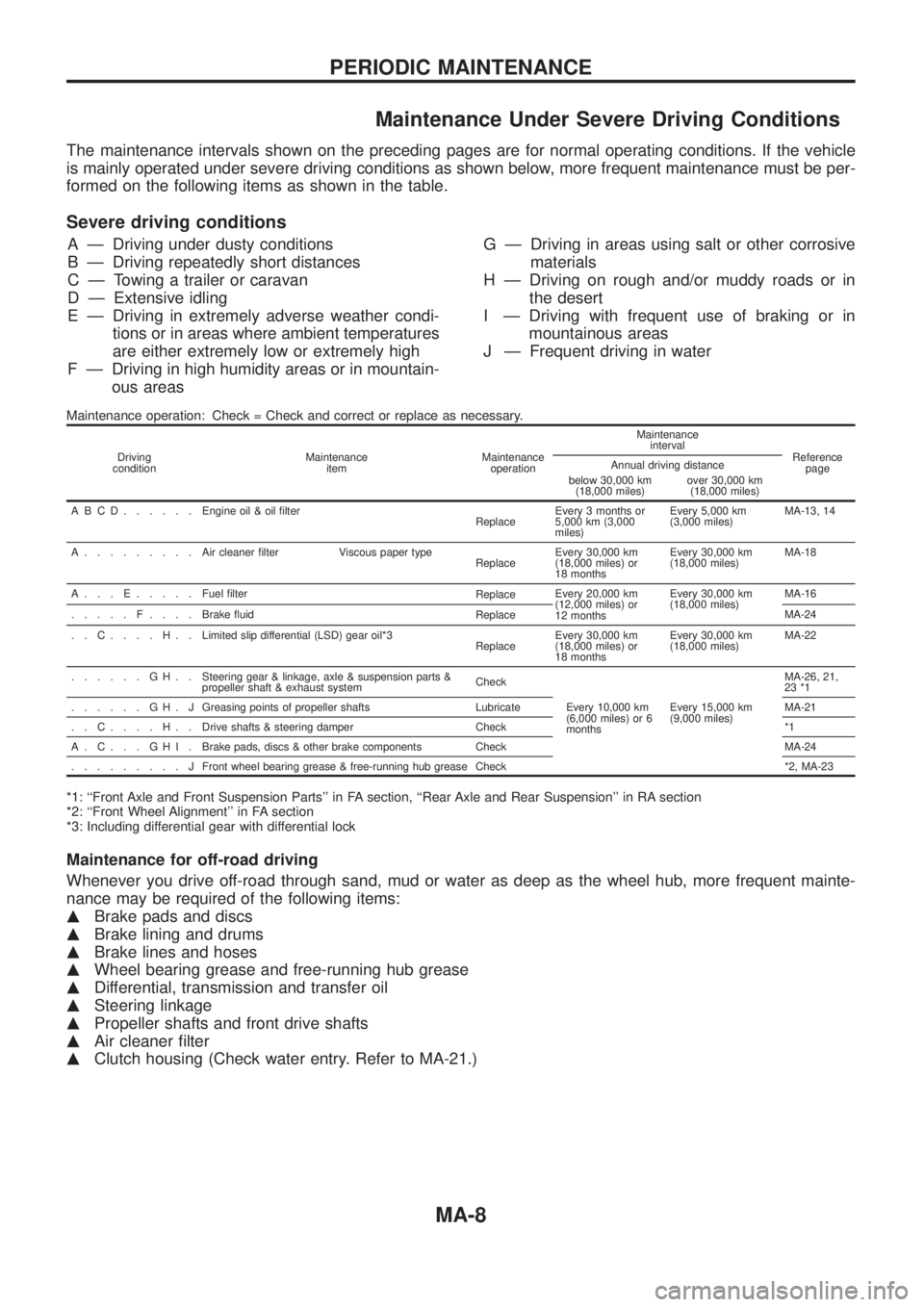
Maintenance Under Severe Driving Conditions
The maintenance intervals shown on the preceding pages are for normal operating conditions. If the vehicle
is mainly operated under severe driving conditions as shown below, more frequent maintenance must be per-
formed on the following items as shown in the table.
Severe driving conditions
A Ð Driving under dusty conditions
B Ð Driving repeatedly short distances
C Ð Towing a trailer or caravan
D Ð Extensive idling
E Ð Driving in extremely adverse weather condi-
tions or in areas where ambient temperatures
are either extremely low or extremely high
F Ð Driving in high humidity areas or in mountain-
ous areasG Ð Driving in areas using salt or other corrosive
materials
H Ð Driving on rough and/or muddy roads or in
the desert
I Ð Driving with frequent use of braking or in
mountainous areas
J Ð Frequent driving in water
Maintenance operation: Check = Check and correct or replace as necessary.
Driving
conditionMaintenance
itemMaintenance
operationMaintenance
interval
Reference
page Annual driving distance
below 30,000 km
(18,000 miles)over 30,000 km
(18,000 miles)
ABCD......Engine oil & oil ®lter
ReplaceEvery 3 months or
5,000 km (3,000
miles)Every 5,000 km
(3,000 miles)MA-13, 14
A.........Aircleaner ®lter Viscous paper type
ReplaceEvery 30,000 km
(18,000 miles) or
18 monthsEvery 30,000 km
(18,000 miles)MA-18
A...E.....Fuel ®lter
ReplaceEvery 20,000 km
(12,000 miles) or
12 monthsEvery 30,000 km
(18,000 miles)MA-16
.....F....Brake ¯uid
ReplaceMA-24
..C....H..Limited slip differential (LSD) gear oil*3
ReplaceEvery 30,000 km
(18,000 miles) or
18 monthsEvery 30,000 km
(18,000 miles)MA-22
......GH..Steering gear & linkage, axle & suspension parts &
propeller shaft & exhaust systemCheck
Every 10,000 km
(6,000 miles) or 6
monthsEvery 15,000 km
(9,000 miles)MA-26, 21,
23 *1
......GH.JGreasing points of propeller shafts Lubricate MA-21
..C....H..Drive shafts & steering damper Check *1
A.C...GHI.Brake pads, discs & other brake components Check MA-24
.........JFront wheel bearing grease & free-running hub grease Check *2, MA-23
*1: ``Front Axle and Front Suspension Parts'' in FA section, ``Rear Axle and Rear Suspension'' in RA section
*2: ``Front Wheel Alignment'' in FA section
*3: Including differential gear with differential lock
Maintenance for off-road driving
Whenever you drive off-road through sand, mud or water as deep as the wheel hub, more frequent mainte-
nance may be required of the following items:
mBrake pads and discs
mBrake lining and drums
mBrake lines and hoses
mWheel bearing grease and free-running hub grease
mDifferential, transmission and transfer oil
mSteering linkage
mPropeller shafts and front drive shafts
mAir cleaner ®lter
mClutch housing (Check water entry. Refer to MA-21.)
PERIODIC MAINTENANCE
MA-8
Page 989 of 1226
Checking Tightening Torque
Checking should be performed while engine is cold.
MANIFOLD BOLTS AND NUTS
Intake and exhaust manifolds:
M10
:25-29Nzm (2.6 - 3.0 kg-m, 19 - 22 ft-lb)
M8
:16-20Nzm (1.6 - 2.0 kg-m, 12 - 14 ft-lb)
Nut
:16-20Nzm (1.6 - 2.0 kg-m, 12 - 14 ft-lb)
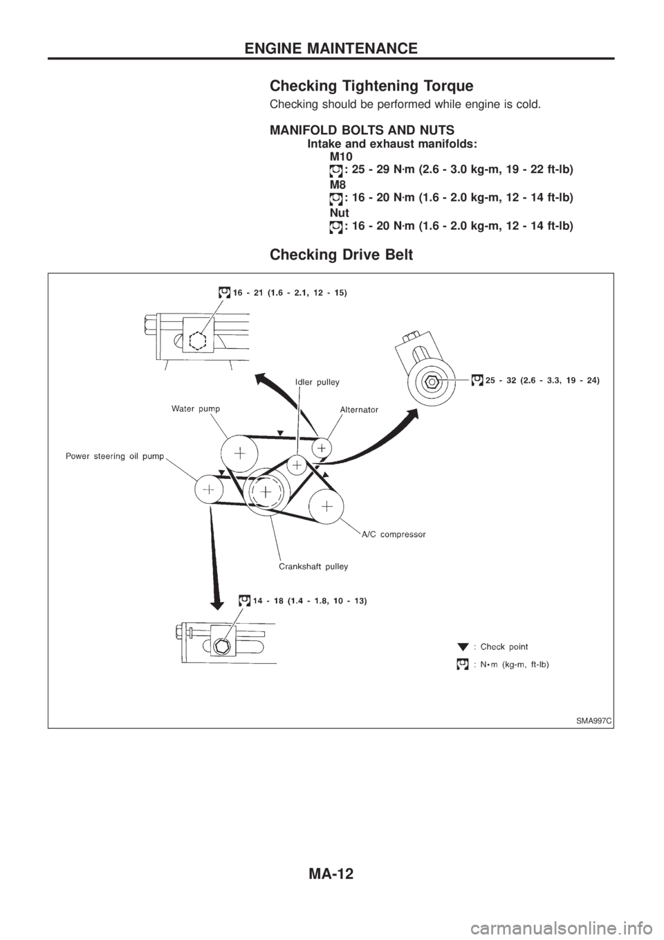
Checking Drive Belt
SMA997C
ENGINE MAINTENANCE
MA-12
Page 990 of 1226

1. Inspect for cracks, fraying, wear or oil adhesion. Replace if
necessary.
The belts should not touch the bottom of the pulley groove.
2. Check drive belt de¯ection by pushing on the belt midway
between pulleys.
Adjust if belt de¯ections exceed the limit.
Unit: mm (in)
Used belt de¯ection
De¯ection of new belt
LimitDe¯ection after
adjustment
Alternator 17 (0.67) 12 - 14 (0.47 - 0.55) 9 - 11 (0.35 - 0.43)
Air conditioner
compressor11 (0.43)7 - 9 (0.28 - 0.35)6 - 8 (0.24 - 0.31)
Power steering oil
pump14 (0.55) 10 - 12 (0.39 - 0.47) 9 - 11 (0.35 - 0.43)
Applied pushing
force98 N (10 kg, 22 lb)
Check drive belt de¯ections when engine is cold.
Changing Engine Oil
WARNING:
+Be careful not to burn yourself, as engine oil is hot.
+Prolonged and repeated contact with used engine oil may
cause skin cancer; try to avoid direct skin contact with
used oil. If skin contact is made, wash thoroughly with
soap or hand cleaner as soon as possible.
1. Warm up engine, and check for oil leakage from engine com-
ponents.
2. Remove oil ®ller cap and drain plug.
3. Drain oil and ®ll with new engine oil.
Oil grade: CCMC PD1 or PD2
Viscosity:
See ``RECOMMENDED FLUIDS AND
LUBRICANTS'', MA-9.
Re®ll oil capacity (approximate):
Without oil ®lter change
6.4!(5-5/8 Imp qt)
With oil ®lter change
5.8!(5-1/8 Imp qt)
CAUTION:
+Be sure to clean and install oil pan drain plug with washer.
Drain plug:
:29-39Nzm (3.0 - 4.0 kg-m, 22 - 29 ft-lb)
+The re®ll capacity changes depending on the oil tempera-
ture and drain time; use these valves as a reference and be
certain to check with the dipstick when changing the oil.
SMA998C
ENGINE MAINTENANCE
Checking Drive Belt (Cont'd)
MA-13
Page 991 of 1226
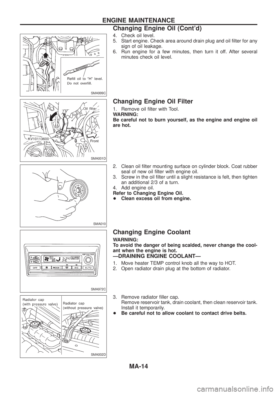
4. Check oil level.
5. Start engine. Check area around drain plug and oil ®lter for any
sign of oil leakage.
6. Run engine for a few minutes, then turn it off. After several
minutes check oil level.
Changing Engine Oil Filter
1. Remove oil ®lter with Tool.
WARNING:
Be careful not to burn yourself, as the engine and engine oil
are hot.
2. Clean oil ®lter mounting surface on cylinder block. Coat rubber
seal of new oil ®lter with engine oil.
3. Screw in the oil ®lter until a slight resistance is felt, then tighten
an additional 2/3 of a turn.
4. Add engine oil.
Refer to Changing Engine Oil.
+Clean excess oil from engine.
Changing Engine Coolant
WARNING:
To avoid the danger of being scalded, never change the cool-
ant when the engine is hot.
ÐDRAINING ENGINE COOLANTÐ
1. Move heater TEMP control knob all the way to HOT.
2. Open radiator drain plug at the bottom of radiator.
3. Remove radiator ®ller cap.
Remove reservoir tank, drain coolant, then clean reservoir tank.
Install it temporarily.
+Be careful not to allow coolant to contact drive belts.
SMA999C
SMA001D
SMA010
SMA972C
SMA002D
ENGINE MAINTENANCE
Changing Engine Oil (Cont'd)
MA-14
Page 992 of 1226
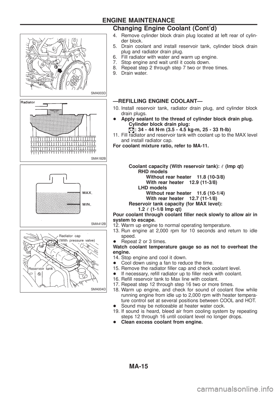
4. Remove cylinder block drain plug located at left rear of cylin-
der block.
5. Drain coolant and install reservoir tank, cylinder block drain
plug and radiator drain plug.
6. Fill radiator with water and warm up engine.
7. Stop engine and wait until it cools down.
8. Repeat step 2 through step 7 two or three times.
9. Drain water.
ÐREFILLING ENGINE COOLANTÐ
10. Install reservoir tank, radiator drain plug, and cylinder block
drain plugs.
+Apply sealant to the thread of cylinder block drain plug.
Cylinder block drain plug:
:34-44Nzm (3.5 - 4.5 kg-m, 25 - 33 ft-lb)
11. Fill radiator and reservoir tank with coolant up to the MAX level
and install radiator cap.
For coolant mixture ratio, refer to MA-11.
Coolant capacity (With reservoir tank):!(Imp qt)
RHD models
Without rear heater 11.8 (10-3/8)
With rear heater 12.9 (11-3/8)
LHD models
Without rear heater 11.6 (10-1/4)
With rear heater 12.7 (11-1/8)
Reservoir tank capacity (for MAX level):
1.2!(1-1/8 Imp qt)
Pour coolant through coolant ®ller neck slowly to allow air in
system to escape.
12. Warm up engine to normal operating temperature.
13. Run engine at 2,000 rpm for 10 seconds and return to idle
speed.
+Repeat 2 or 3 times.
Watch coolant temperature gauge so as not to overheat the
engine.
14. Stop engine and cool it down.
+Cool down using a fan to reduce the time.
15. Remove the radiator ®ller cap and check coolant level.
+If necessary, re®ll radiator up to ®ller neck with coolant.
16. Re®ll reservoir tank to Max line with coolant.
17. Repeat step 12 through step 16 two or more times.
18. Warm up engine, and check for sound of coolant ¯ow while
running engine from idle up to 2,000 rpm with heater tempera-
ture control set at several positions between COOL and HOT.
+Sound may be noticeable at heater water cock.
19. If sound is heard, bleed air from cooling system by repeating
steps 12 through 16 until coolant level no longer drops.
+Clean excess coolant from engine.
SMA003D
SMA182B
SMA412B
SMA004D
ENGINE MAINTENANCE
Changing Engine Coolant (Cont'd)
MA-15
Page 993 of 1226
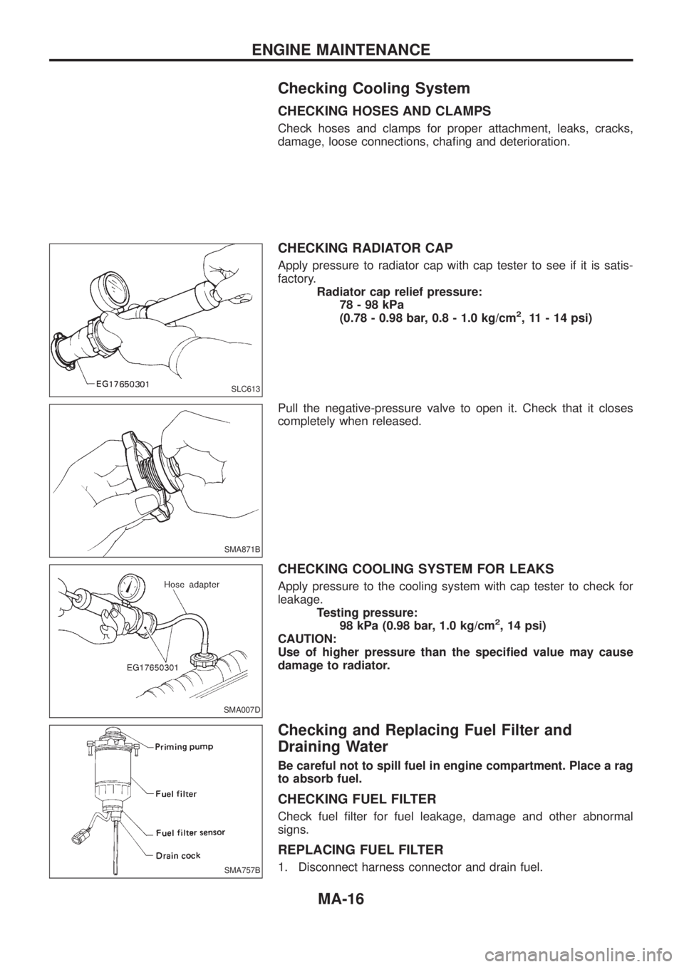
Checking Cooling System
CHECKING HOSES AND CLAMPS
Check hoses and clamps for proper attachment, leaks, cracks,
damage, loose connections, cha®ng and deterioration.
CHECKING RADIATOR CAP
Apply pressure to radiator cap with cap tester to see if it is satis-
factory.
Radiator cap relief pressure:
78-98kPa
(0.78 - 0.98 bar, 0.8 - 1.0 kg/cm
2, 11 - 14 psi)
Pull the negative-pressure valve to open it. Check that it closes
completely when released.
CHECKING COOLING SYSTEM FOR LEAKS
Apply pressure to the cooling system with cap tester to check for
leakage.
Testing pressure:
98 kPa (0.98 bar, 1.0 kg/cm
2, 14 psi)
CAUTION:
Use of higher pressure than the speci®ed value may cause
damage to radiator.
Checking and Replacing Fuel Filter and
Draining Water
Be careful not to spill fuel in engine compartment. Place a rag
to absorb fuel.
CHECKING FUEL FILTER
Check fuel ®lter for fuel leakage, damage and other abnormal
signs.
REPLACING FUEL FILTER
1. Disconnect harness connector and drain fuel.
SLC613
SMA871B
SMA007D
SMA757B
ENGINE MAINTENANCE
MA-16
Page 994 of 1226
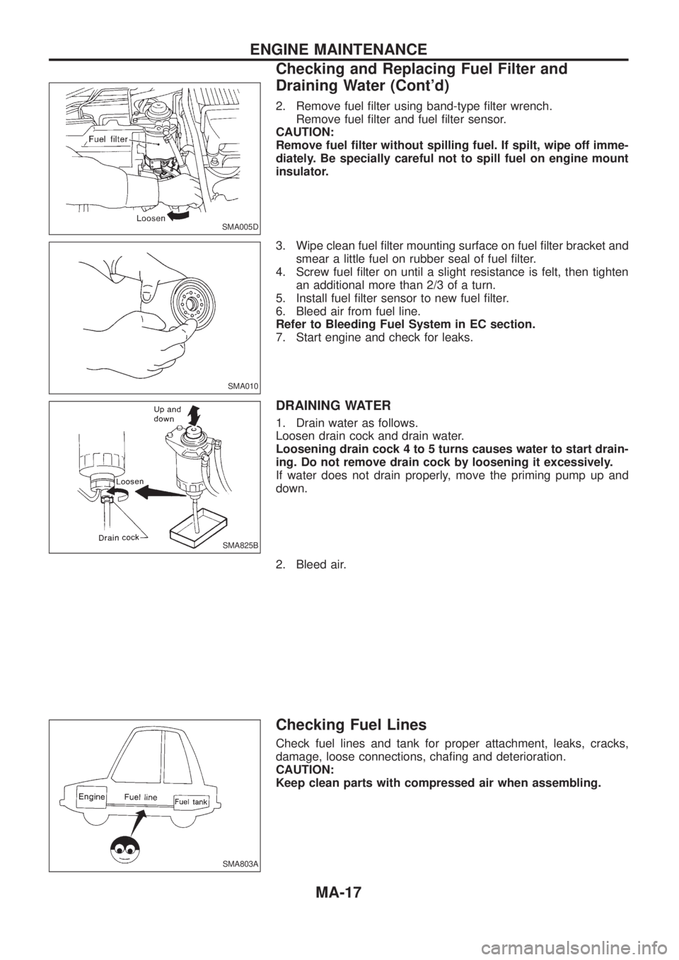
2. Remove fuel ®lter using band-type ®lter wrench.
Remove fuel ®lter and fuel ®lter sensor.
CAUTION:
Remove fuel ®lter without spilling fuel. If spilt, wipe off imme-
diately. Be specially careful not to spill fuel on engine mount
insulator.
3. Wipe clean fuel ®lter mounting surface on fuel ®lter bracket and
smear a little fuel on rubber seal of fuel ®lter.
4. Screw fuel ®lter on until a slight resistance is felt, then tighten
an additional more than 2/3 of a turn.
5. Install fuel ®lter sensor to new fuel ®lter.
6. Bleed air from fuel line.
Refer to Bleeding Fuel System in EC section.
7. Start engine and check for leaks.
DRAINING WATER
1. Drain water as follows.
Loosen drain cock and drain water.
Loosening drain cock 4 to 5 turns causes water to start drain-
ing. Do not remove drain cock by loosening it excessively.
If water does not drain properly, move the priming pump up and
down.
2. Bleed air.
Checking Fuel Lines
Check fuel lines and tank for proper attachment, leaks, cracks,
damage, loose connections, cha®ng and deterioration.
CAUTION:
Keep clean parts with compressed air when assembling.
SMA005D
SMA010
SMA825B
SMA803A
ENGINE MAINTENANCE
Checking and Replacing Fuel Filter and
Draining Water (Cont'd)
MA-17
Page 995 of 1226
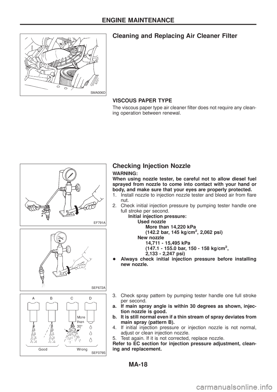
Cleaning and Replacing Air Cleaner Filter
VISCOUS PAPER TYPE
The viscous paper type air cleaner ®lter does not require any clean-
ing operation between renewal.
Checking Injection Nozzle
WARNING:
When using nozzle tester, be careful not to allow diesel fuel
sprayed from nozzle to come into contact with your hand or
body, and make sure that your eyes are properly protected.
1. Install nozzle to injection nozzle tester and bleed air from ¯are
nut.
2. Check initial injection pressure by pumping tester handle one
full stroke per second.
Initial injection pressure:
Used nozzle
More than 14,220 kPa
(142.2 bar, 145 kg/cm
2, 2,062 psi)
New nozzle
14,711 - 15,495 kPa
(147.1 - 155.0 bar, 150 - 158 kg/cm
2,
2,133 - 2,247 psi)
+Always check initial injection pressure before installing
new nozzle.
3. Check spray pattern by pumping tester handle one full stroke
per second.
a. If main spray angle is within 30 degrees as shown, injec-
tion nozzle is good.
b. It is still normal even if a thin stream of spray deviates from
main spray (pattern B).
4. If initial injection pressure or injection nozzle is not normal,
adjust or clean injection nozzle.
5. Test again. If it is not corrected, replace nozzle.
Refer to EC section for injection pressure adjustment, clean-
ing and replacement.
SMA006D
EF791A
SEF672A
SEF079S
ENGINE MAINTENANCE
MA-18