Page 686 of 1226
Inspection
Visually check the condition of timing belt.
Replace if any abnormality is found.
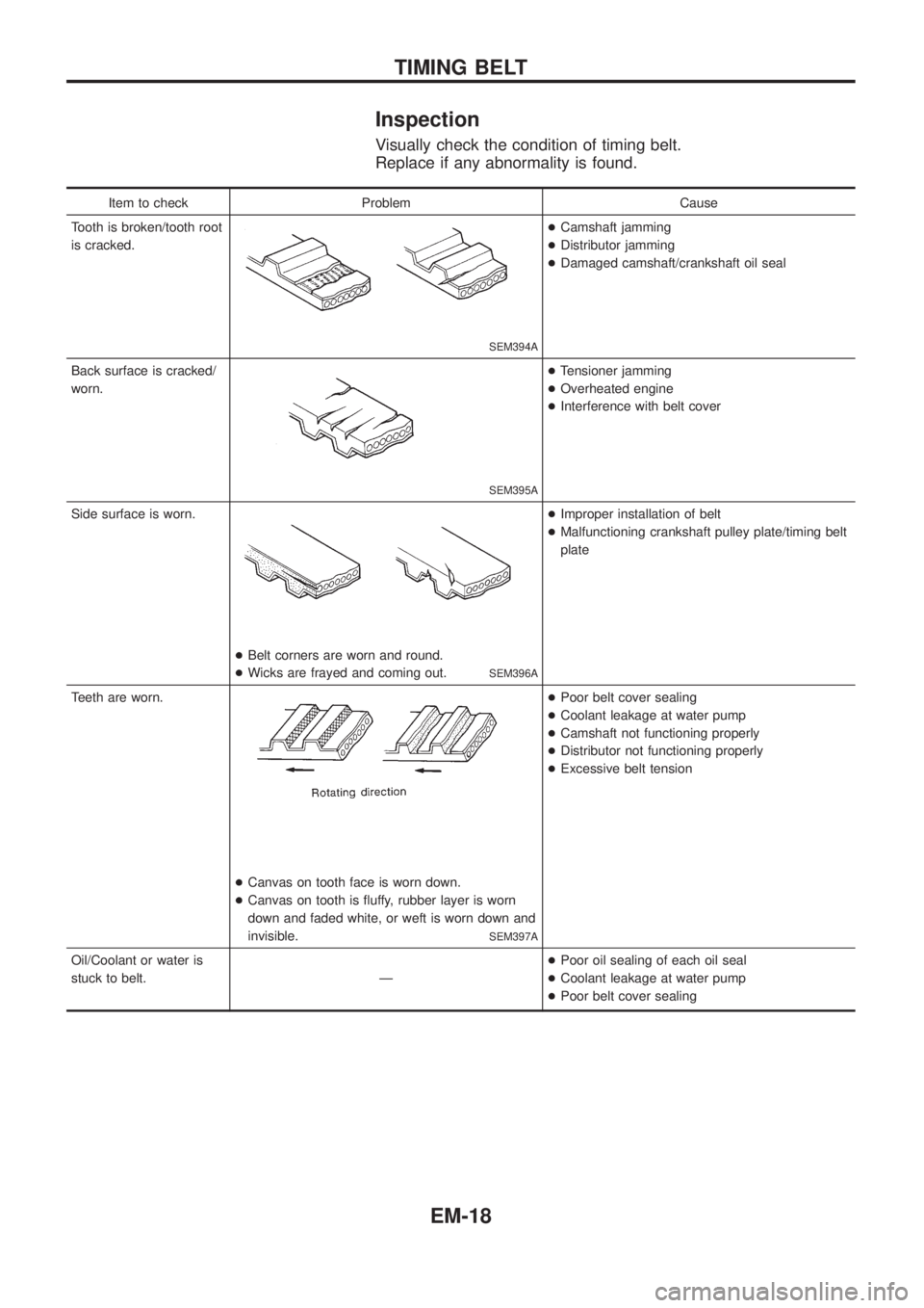
Item to check Problem Cause
Tooth is broken/tooth root
is cracked.
SEM394A
+Camshaft jamming
+Distributor jamming
+Damaged camshaft/crankshaft oil seal
Back surface is cracked/
worn.
SEM395A
+Tensioner jamming
+Overheated engine
+Interference with belt cover
Side surface is worn.
+Belt corners are worn and round.
+Wicks are frayed and coming out.
SEM396A
+Improper installation of belt
+Malfunctioning crankshaft pulley plate/timing belt
plate
Teeth are worn.
+Canvas on tooth face is worn down.
+Canvas on tooth is ¯uffy, rubber layer is worn
down and faded white, or weft is worn down and
invisible.
SEM397A
+Poor belt cover sealing
+Coolant leakage at water pump
+Camshaft not functioning properly
+Distributor not functioning properly
+Excessive belt tension
Oil/Coolant or water is
stuck to belt. Ð+Poor oil sealing of each oil seal
+Coolant leakage at water pump
+Poor belt cover sealing
TIMING BELT
EM-18
Page 693 of 1226
Inspection
OIL AND WATER TUBES
Check tubes for clogging.
ROTOR SHAFT
1. Check rotor shaft for smooth rotating.
2. Check rotor shaft for carbon deposits.
SEM796C
SEM798C
SEM799C
TURBOCHARGER
EM-25
Page 694 of 1226
3. Measure runout of rotor shaft.
Runout (Total indicator reading):
0.056 - 0.127 mm (0.0022 - 0.0050 in)
4. Measure end play of rotor shaft.
End play:
0.013 - 0.097 mm (0.0005 - 0.0038 in)
TURBINE WHEEL
Check turbine wheel for the following:
+Oil
+Carbon deposits
+Deformed ®ns
+Contact with turbine housing
COMPRESSOR WHEEL
Check compressor wheel for the following:
+Oil
+Deformed ®ns
+Contact with compressor housing
WASTEGATE VALVE
Remove rod pin and check wastegate valve for cracks, deformation
and smooth movement.
Check valve seat surface for smoothness.
SEM800C
SEM801C
SEM802C
SEM803C
SEM804C
TURBOCHARGER
Inspection (Cont'd)
EM-26
Page 700 of 1226
Inspection
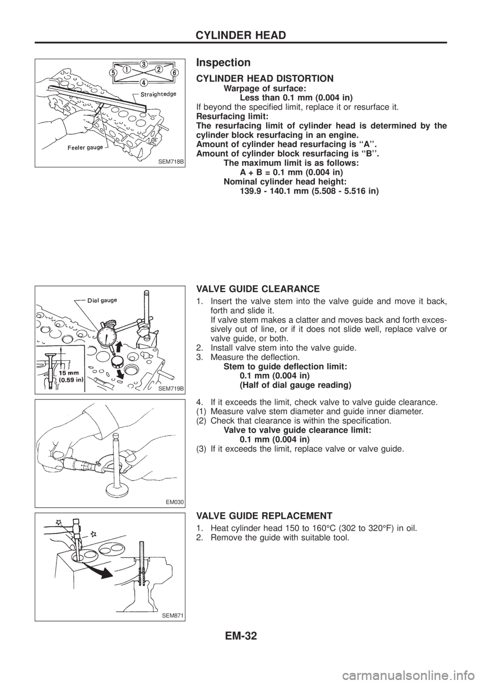
CYLINDER HEAD DISTORTION
Warpage of surface:
Less than 0.1 mm (0.004 in)
If beyond the speci®ed limit, replace it or resurface it.
Resurfacing limit:
The resurfacing limit of cylinder head is determined by the
cylinder block resurfacing in an engine.
Amount of cylinder head resurfacing is ``A''.
Amount of cylinder block resurfacing is ``B''.
The maximum limit is as follows:
A + B = 0.1 mm (0.004 in)
Nominal cylinder head height:
139.9 - 140.1 mm (5.508 - 5.516 in)
VALVE GUIDE CLEARANCE
1. Insert the valve stem into the valve guide and move it back,
forth and slide it.
If valve stem makes a clatter and moves back and forth exces-
sively out of line, or if it does not slide well, replace valve or
valve guide, or both.
2. Install valve stem into the valve guide.
3. Measure the de¯ection.
Stem to guide de¯ection limit:
0.1 mm (0.004 in)
(Half of dial gauge reading)
4. If it exceeds the limit, check valve to valve guide clearance.
(1) Measure valve stem diameter and guide inner diameter.
(2) Check that clearance is within the speci®cation.
Valve to valve guide clearance limit:
0.1 mm (0.004 in)
(3) If it exceeds the limit, replace valve or valve guide.
VALVE GUIDE REPLACEMENT
1. Heat cylinder head 150 to 160ÉC (302 to 320ÉF) in oil.
2. Remove the guide with suitable tool.
SEM718B
SEM719B
EM030
SEM871
CYLINDER HEAD
EM-32
Page 701 of 1226
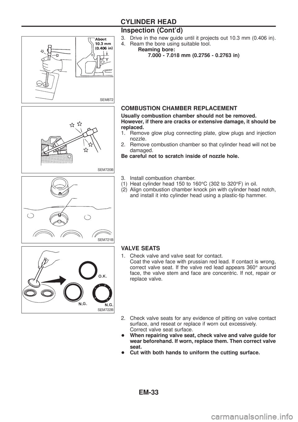
3. Drive in the new guide until it projects out 10.3 mm (0.406 in).
4. Ream the bore using suitable tool.
Reaming bore:
7.000 - 7.018 mm (0.2756 - 0.2763 in)
COMBUSTION CHAMBER REPLACEMENT
Usually combustion chamber should not be removed.
However, if there are cracks or extensive damage, it should be
replaced.
1. Remove glow plug connecting plate, glow plugs and injection
nozzle.
2. Remove combustion chamber so that cylinder head will not be
damaged.
Be careful not to scratch inside of nozzle hole.
3. Install combustion chamber.
(1) Heat cylinder head 150 to 160ÉC (302 to 320ÉF) in oil.
(2) Align combustion chamber knock pin with cylinder head notch,
and install it into cylinder head using a plastic-tip hammer.
VALVE SEATS
1. Check valve and valve seat for contact.
Coat the valve face with prussian red lead. If contact is wrong,
correct valve seat. If the valve red lead appears 360É around
face, the valve stem and face are concentric. If not, repair or
replace valve.
2. Check valve seats for any evidence of pitting on valve contact
surface, and reseat or replace if worn out excessively.
Correct valve seat surface.
+When repairing valve seat, check valve and valve guide for
wear beforehand. If worn, replace them. Then correct valve
seat.
+Cut with both hands to uniform the cutting surface.
SEM872
SEM720B
SEM721B
SEM722B
CYLINDER HEAD
Inspection (Cont'd)
EM-33
Page 706 of 1226
Assembly
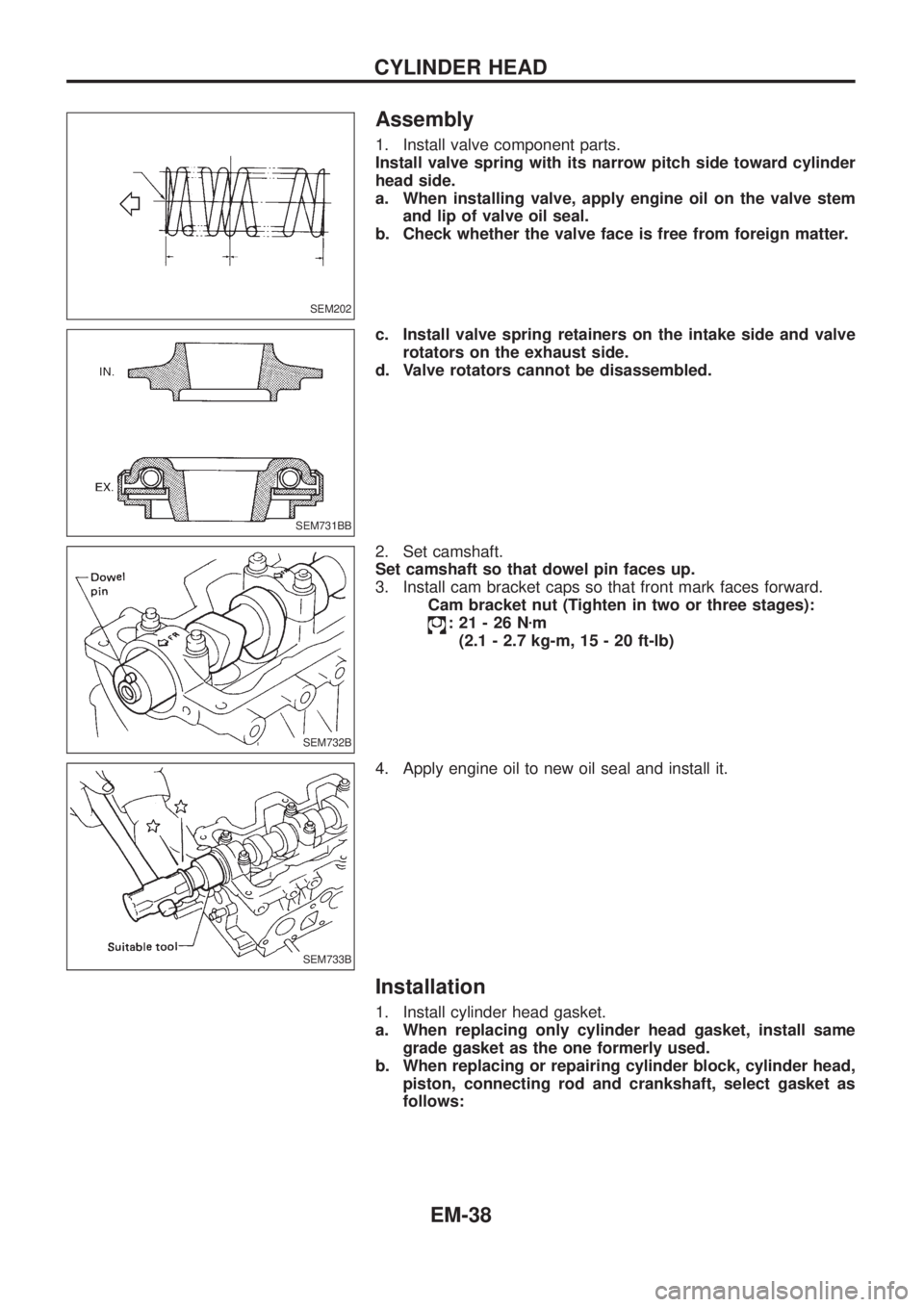
1. Install valve component parts.
Install valve spring with its narrow pitch side toward cylinder
head side.
a. When installing valve, apply engine oil on the valve stem
and lip of valve oil seal.
b. Check whether the valve face is free from foreign matter.
c. Install valve spring retainers on the intake side and valve
rotators on the exhaust side.
d. Valve rotators cannot be disassembled.
2. Set camshaft.
Set camshaft so that dowel pin faces up.
3. Install cam bracket caps so that front mark faces forward.
Cam bracket nut (Tighten in two or three stages):
:21-26Nzm
(2.1 - 2.7 kg-m, 15 - 20 ft-lb)
4. Apply engine oil to new oil seal and install it.
Installation
1. Install cylinder head gasket.
a. When replacing only cylinder head gasket, install same
grade gasket as the one formerly used.
b. When replacing or repairing cylinder block, cylinder head,
piston, connecting rod and crankshaft, select gasket as
follows:
SEM202
SEM731BB
SEM732B
SEM733B
CYLINDER HEAD
EM-38
Page 716 of 1226
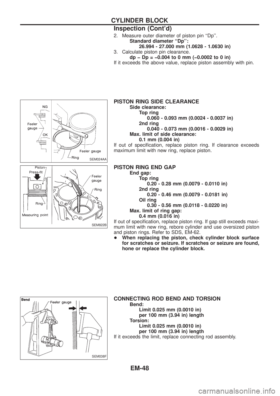
2. Measure outer diameter of piston pin ``Dp''.
Standard diameter ``Dp'':
26.994 - 27.000 mm (1.0628 - 1.0630 in)
3. Calculate piston pin clearance.
dp þ Dp = þ0.004 to 0 mm (þ0.0002 to 0 in)
If it exceeds the above value, replace piston assembly with pin.
PISTON RING SIDE CLEARANCE
Side clearance:
Top ring
0.060 - 0.093 mm (0.0024 - 0.0037 in)
2nd ring
0.040 - 0.073 mm (0.0016 - 0.0029 in)
Max. limit of side clearance:
0.1 mm (0.004 in)
If out of speci®cation, replace piston ring. If clearance exceeds
maximum limit with new ring, replace piston.
PISTON RING END GAP
End gap:
Top ring
0.20 - 0.28 mm (0.0079 - 0.0110 in)
2nd ring
0.20 - 0.46 mm (0.0079 - 0.0181 in)
Oil ring
0.30 - 0.56 mm (0.0118 - 0.0220 in)
Max. limit of ring gap:
0.4 mm (0.016 in)
If out of speci®cation, replace piston ring. If gap still exceeds maxi-
mum limit with new ring, rebore cylinder and use oversized piston
and piston rings. Refer to SDS, EM-62.
+When replacing the piston, check cylinder block surface
for scratches or seizure. If scratches or seizure are found,
hone or replace the cylinder block.
CONNECTING ROD BEND AND TORSION
Bend:
Limit 0.025 mm (0.0010 in)
per 100 mm (3.94 in) length
Torsion:
Limit 0.025 mm (0.0010 in)
per 100 mm (3.94 in) length
If it exceeds the limit, replace connecting rod assembly.
SEM024AA
SEM822B
SEM038F
CYLINDER BLOCK
Inspection (Cont'd)
EM-48
Page 721 of 1226
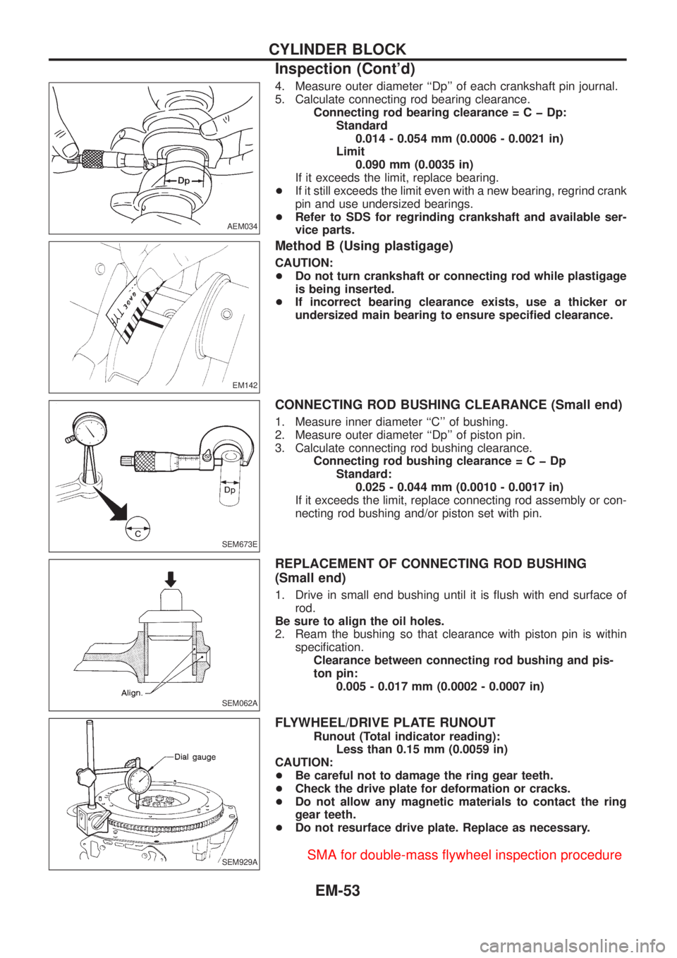
4. Measure outer diameter ``Dp'' of each crankshaft pin journal.
5. Calculate connecting rod bearing clearance.
Connecting rod bearing clearance=CþDp:
Standard
0.014 - 0.054 mm (0.0006 - 0.0021 in)
Limit
0.090 mm (0.0035 in)
If it exceeds the limit, replace bearing.
+If it still exceeds the limit even with a new bearing, regrind crank
pin and use undersized bearings.
+Refer to SDS for regrinding crankshaft and available ser-
vice parts.
Method B (Using plastigage)
CAUTION:
+Do not turn crankshaft or connecting rod while plastigage
is being inserted.
+If incorrect bearing clearance exists, use a thicker or
undersized main bearing to ensure speci®ed clearance.
CONNECTING ROD BUSHING CLEARANCE (Small end)
1. Measure inner diameter ``C'' of bushing.
2. Measure outer diameter ``Dp'' of piston pin.
3. Calculate connecting rod bushing clearance.
Connecting rod bushing clearance=CþDp
Standard:
0.025 - 0.044 mm (0.0010 - 0.0017 in)
If it exceeds the limit, replace connecting rod assembly or con-
necting rod bushing and/or piston set with pin.
REPLACEMENT OF CONNECTING ROD BUSHING
(Small end)
1. Drive in small end bushing until it is ¯ush with end surface of
rod.
Be sure to align the oil holes.
2. Ream the bushing so that clearance with piston pin is within
speci®cation.
Clearance between connecting rod bushing and pis-
ton pin:
0.005 - 0.017 mm (0.0002 - 0.0007 in)
FLYWHEEL/DRIVE PLATE RUNOUT
Runout (Total indicator reading):
Less than 0.15 mm (0.0059 in)
CAUTION:
+Be careful not to damage the ring gear teeth.
+Check the drive plate for deformation or cracks.
+Do not allow any magnetic materials to contact the ring
gear teeth.
+Do not resurface drive plate. Replace as necessary.
AEM034
EM142
SEM673E
SEM062A
SEM929A
CYLINDER BLOCK
Inspection (Cont'd)
EM-53