Page 1175 of 1226

Bleeding Hydraulic System
1. Raise front end of vehicle until wheels are clear of the ground.
2. Add ¯uid into oil tank to speci®ed level. Then, quickly turn steer-
ing wheel fully to right and left and lightly touch steering stop-
pers.
Repeat steering wheel operation until ¯uid level no longer
decreases.
3. Start engine.
Repeat step 2 above.
+Incomplete air bleeding will cause the following to occur. When
this happens, bleed air again.
a. Air bubbles in reservoir tank
b. Clicking noise in oil pump
c. Excessive buzzing in oil pump
Fluid noise may occur in the valve or oil pump. This is common
when the vehicle is stationary or while turning steering wheel
slowly. This does not affect performance or durability of the system.
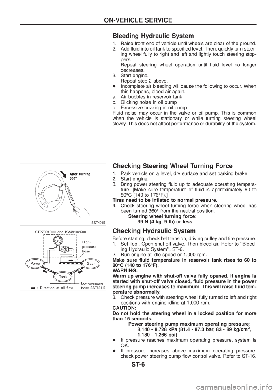
Checking Steering Wheel Turning Force
1. Park vehicle on a level, dry surface and set parking brake.
2. Start engine.
3. Bring power steering ¯uid up to adequate operating tempera-
ture. [Make sure temperature of ¯uid is approximately 60 to
80ÉC (140 to 176ÉF).]
Tires need to be in¯ated to normal pressure.
4. Check steering wheel turning force when steering wheel has
been turned 360É from the neutral position.
Steering wheel turning force:
39 N (4 kg, 9 lb) or less
Checking Hydraulic System
Before starting, check belt tension, driving pulley and tire pressure.
1. Set Tool. Open shut-off valve. Then bleed air. Refer to ``Bleed-
ing Hydraulic System'', ST-6.
2. Run engine at idle speed or 1,000 rpm.
Make sure ¯uid temperature in reservoir tank rises to 60 to
80ÉC (140 to 176ÉF).
WARNING:
Warm up engine with shut-off valve fully opened. If engine is
started with shut-off valve closed, ¯uid pressure in the power
steering pump increases to maximum. This will raise ¯uid tem-
perature abnormally.
3. Check pressure with steering wheel fully turned to left and right
positions with engine idling at 1,000 rpm.
CAUTION:
Do not hold the steering wheel in a locked position for more
than 15 seconds.
Power steering pump maximum operating pressure:
8,140 - 8,728 kPa (81.4 - 87.3 bar, 83 - 89 kg/cm
2,
1,180 - 1,266 psi)
+If pressure reaches maximum operating pressure, system is
OK.
+If pressure increases above maximum operating pressure,
check power steering pump ¯ow control valve. Refer to ST-16.
SST491B
SST834-E
ON-VEHICLE SERVICE
ST-6
Page 1189 of 1226

Disassembly
TIE-ROD
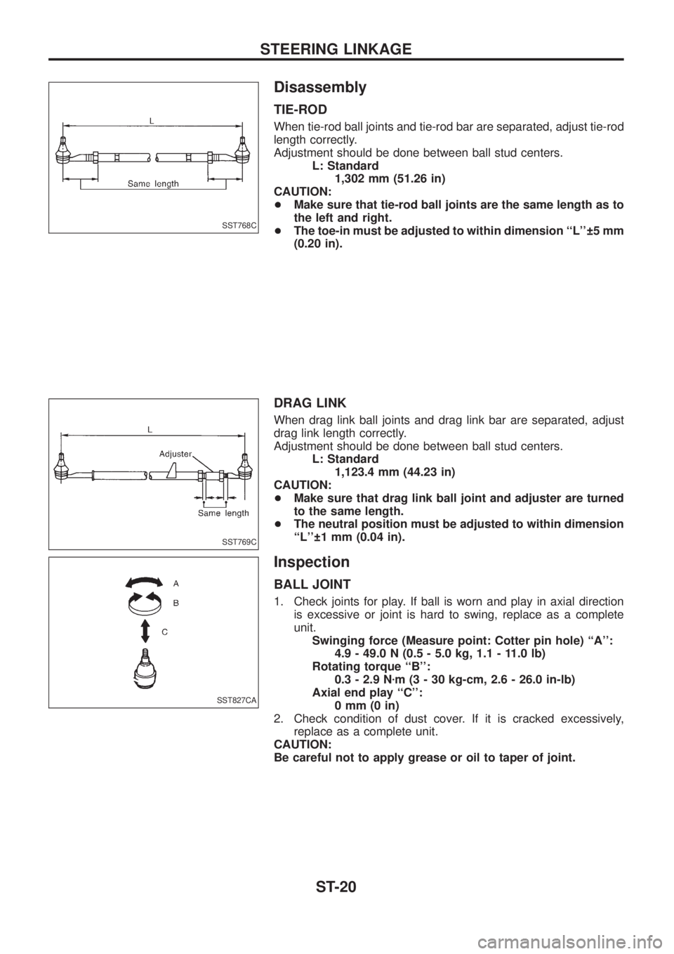
When tie-rod ball joints and tie-rod bar are separated, adjust tie-rod
length correctly.
Adjustment should be done between ball stud centers.
L: Standard
1,302 mm (51.26 in)
CAUTION:
+Make sure that tie-rod ball joints are the same length as to
the left and right.
+The toe-in must be adjusted to within dimension ``L'' 5 mm
(0.20 in).
DRAG LINK
When drag link ball joints and drag link bar are separated, adjust
drag link length correctly.
Adjustment should be done between ball stud centers.
L: Standard
1,123.4 mm (44.23 in)
CAUTION:
+Make sure that drag link ball joint and adjuster are turned
to the same length.
+The neutral position must be adjusted to within dimension
``L'' 1 mm (0.04 in).
Inspection
BALL JOINT
1. Check joints for play. If ball is worn and play in axial direction
is excessive or joint is hard to swing, replace as a complete
unit.
Swinging force (Measure point: Cotter pin hole) ``A'':
4.9 - 49.0 N (0.5 - 5.0 kg, 1.1 - 11.0 lb)
Rotating torque ``B'':
0.3 - 2.9 Nzm (3 - 30 kg-cm, 2.6 - 26.0 in-lb)
Axial end play ``C'':
0mm(0in)
2. Check condition of dust cover. If it is cracked excessively,
replace as a complete unit.
CAUTION:
Be careful not to apply grease or oil to taper of joint.
SST768C
SST769C
SST827CA
STEERING LINKAGE
ST-20
Page 1190 of 1226
TIE-ROD AND DRAG LINK
Check tie-rod and drag link for breakage, bends and cracks, and
replace with a new one if necessary.
FIXING LOCATION
+Check ®xing location (nuts and cotter pins) for looseness, play
and breakage.
+When looseness or play is found, check for wear and tapered
portion of ball joints, pitman arm and knuckle arms.
+When reassembling each joint, use new cotter pins.
STEERING DAMPER
Check for oil leakage and measure damping force. Replace if nec-
essary.
Damping force:
at 0.3 m (1.0 ft)/sec
4,443 N (453 kg, 999 lb)
... Extended direction
3,315 N (338 kg, 745 lb)
... Compressed direction
STEERING LINKAGE
Inspection (Cont'd)
ST-21
Page 1193 of 1226

TRANSFER
SECTION
TF
CONTENTS
PREPARATION................................................................1
Special Service Tools ..................................................1
Commercial Service Tools ...........................................2
NOISE, VIBRATION AND HARSHNESS (NVH)
TROUBLESHOOTING.....................................................3
NVH Troubleshooting Chart.........................................3
DESCRIPTION.................................................................4
Cross-sectional View ...................................................4
ON-VEHICLE SERVICE..................................................5
Replacing Oil Seal .......................................................5
Checking Position Switch ............................................7
REMOVAL AND INSTALLATION....................................8
Removal .......................................................................8
Installation ....................................................................8
TRANSFER GEAR CONTROL.......................................9
MAJOR OVERHAUL.....................................................10
Case Components .....................................................10
Gear Components ..................................................... 11Shift Control Components .........................................12
DISASSEMBLY..............................................................13
REPAIR FOR COMPONENT PARTS............................19
Mainshaft ...................................................................19
Front Drive Shaft .......................................................20
Counter Gear .............................................................21
Main Gear ..................................................................22
Front Case .................................................................24
Front Case Cover ......................................................24
Center Case...............................................................24
Bearing Retainer ........................................................25
Rear Case..................................................................25
Shift Control Components .........................................26
ASSEMBLY....................................................................27
SERVICE DATA AND SPECIFICATIONS (SDS)..........33
General Speci®cations ...............................................33
Inspection and Adjustment ........................................33
TF
Page 1196 of 1226
NVH Troubleshooting Chart
Use the chart below to help you ®nd the cause of the problem. The numbers indicate the order of the inspec-
tion. If necessary, repair or replace these parts.
TRANSFER
Reference page
Refer to MA section (``Checking Transfer Fluid'',
``CHASSIS AND BODY MAINTENANCE'').
TF-10
TF-10
TF-10, TF-12
TF-12
TF-11
TF-11
TF-11
TF-11
SUSPECTED PARTS (Possible cause)
FLUID (Level low)
FLUID (Wrong)
FLUID (Level too high)
LIQUID GASKET (Damaged)
OIL SEAL (Worn or damaged)
CHECK SPRING AND CHECK BALL (Worn or damaged)
SHIFT FORK (Worn)
GEAR (Worn or damaged)
BEARING (Worn or damaged)
BAULK RING (Worn or damaged)
SHIFTING INSERT (Damaged)
SymptomNoise 1 2 3 3
Fluid leakage3122
Hard to shift or will not shift 1 1 2 2
Jumps out of gear 1 2 2
NOISE, VIBRATION AND HARSHNESS (NVH) TROUBLESHOOTING
TF-3
Page 1207 of 1226
5. Remove speedometer drive gear and oil gutter.
6. Remove snap ring from 2-4 shift rod.
7. Check front drive sprocket end play.
a. While holding front drive sprocket forward as far as it will go,
measure distance ``A'' between rear surface of front drive
sprocket and front surface of 2-4 coupling sleeve.
b. While holding front drive sprocket back as far as it will go,
measure distance ``B'' as same as step a.
c. Determine front drive sprocket end play to be used by the fol-
lowing equation.
Front drive sprocket end play = A þ B
Standard:
0.20 - 0.35 mm (0.0079 - 0.0138 in)
+If not within speci®cation, disassemble and check contact sur-
face of gear to hub, washer, bushing, needle bearing and shaft.
8. Shift 2-4 coupling sleeve to 2WD position.
SMT106B
SMT107B
SMT108B
SMT110B
DISASSEMBLY
TF-14