2006 NISSAN PATROL turn signal
[x] Cancel search: turn signalPage 243 of 1226
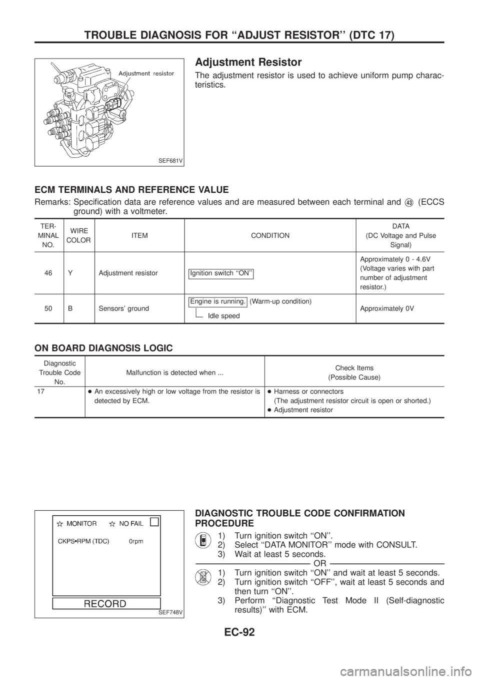
Adjustment Resistor
The adjustment resistor is used to achieve uniform pump charac-
teristics.
ECM TERMINALS AND REFERENCE VALUE
Remarks: Speci®cation data are reference values and are measured between each terminal andV43(ECCS
ground) with a voltmeter.
TER-
MINAL
NO.WIRE
COLORITEM CONDITIONDATA
(DC Voltage and Pulse
Signal)
46 Y Adjustment resistor Ignition switch ``ON''
Approximately 0 - 4.6V
(Voltage varies with part
number of adjustment
resistor.)
50 B Sensors' groundEngine is running.
(Warm-up condition)
Idle speedApproximately 0V
ON BOARD DIAGNOSIS LOGIC
Diagnostic
Trouble Code
No.Malfunction is detected when ...Check Items
(Possible Cause)
17+An excessively high or low voltage from the resistor is
detected by ECM.+Harness or connectors
(The adjustment resistor circuit is open or shorted.)
+Adjustment resistor
DIAGNOSTIC TROUBLE CODE CONFIRMATION
PROCEDURE
1) Turn ignition switch ``ON''.
2) Select ``DATA MONITOR'' mode with CONSULT.
3) Wait at least 5 seconds.
-------------------------------------------------------------------------------------------------------------------------------------------------------------------------------------------------------------------------------------------------------OR-------------------------------------------------------------------------------------------------------------------------------------------------------------------------------------------------------------------------------------------------------
1) Turn ignition switch ``ON'' and wait at least 5 seconds.
2) Turn ignition switch ``OFF'', wait at least 5 seconds and
then turn ``ON''.
3) Perform ``Diagnostic Test Mode II (Self-diagnostic
results)'' with ECM.
SEF681V
SEF748V
TROUBLE DIAGNOSIS FOR ``ADJUST RESISTOR'' (DTC 17)
EC-92
Page 247 of 1226
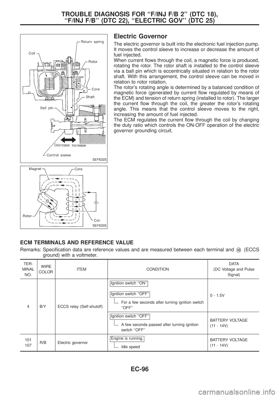
Electric Governor
The electric governor is built into the electronic fuel injection pump.
It moves the control sleeve to increase or decrease the amount of
fuel injected.
When current ¯ows through the coil, a magnetic force is produced,
rotating the rotor. The rotor shaft is installed to the control sleeve
via a ball pin which is eccentrically situated in relation to the rotor
shaft. With this arrangement, the control sleeve can be moved in
relation to rotor rotation.
The rotor's rotating angle is determined by a balanced condition of
magnetic force (generated by current ¯ow regulated by means of
the ECM) and tension of return spring (installed to rotor). The larger
the current ¯ow through the coil, the greater the rotor's rotating
angle. This means that the control sleeve moves to the right,
increasing the amount of fuel injected.
The ECM regulates the current ¯ow through the coil by changing
the duty ratio which controls the ON-OFF operation of the electric
governor grounding circuit.
ECM TERMINALS AND REFERENCE VALUE
Remarks: Speci®cation data are reference values and are measured between each terminal andV43(ECCS
ground) with a voltmeter.
TER-
MINAL
NO.WIRE
COLORITEM CONDITIONDATA
(DC Voltage and Pulse
Signal)
4 B/Y ECCS relay (Self-shutoff)Ignition switch ``ON''
Ignition switch ``OFF''
For a few seconds after turning ignition switch
``OFF''0 - 1.5V
Ignition switch ``OFF''
A few seconds passed after turning ignition
switch ``OFF''BATTERY VOLTAGE
(11 - 14V)
101
107R/B Electric governorEngine is running.
Idle speedBATTERY VOLTAGE
(11 - 14V)
SEF632S
SEF633S
TROUBLE DIAGNOSIS FOR ``F/INJ F/B 2'' (DTC 18),
``F/INJ F/B'' (DTC 22), ``ELECTRIC GOV'' (DTC 25)
EC-96
Page 252 of 1226
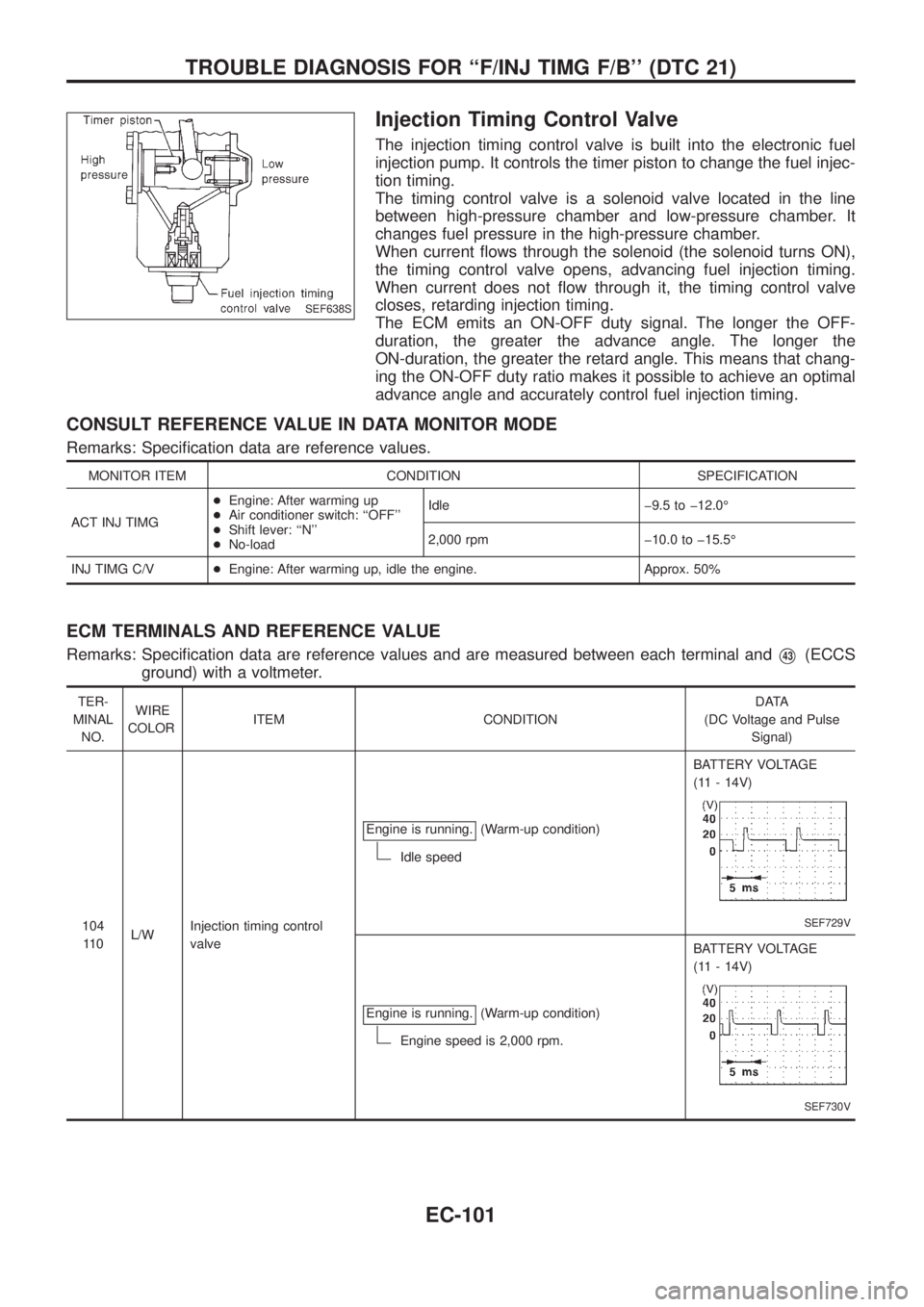
Injection Timing Control Valve
The injection timing control valve is built into the electronic fuel
injection pump. It controls the timer piston to change the fuel injec-
tion timing.
The timing control valve is a solenoid valve located in the line
between high-pressure chamber and low-pressure chamber. It
changes fuel pressure in the high-pressure chamber.
When current ¯ows through the solenoid (the solenoid turns ON),
the timing control valve opens, advancing fuel injection timing.
When current does not ¯ow through it, the timing control valve
closes, retarding injection timing.
The ECM emits an ON-OFF duty signal. The longer the OFF-
duration, the greater the advance angle. The longer the
ON-duration, the greater the retard angle. This means that chang-
ing the ON-OFF duty ratio makes it possible to achieve an optimal
advance angle and accurately control fuel injection timing.
CONSULT REFERENCE VALUE IN DATA MONITOR MODE
Remarks: Speci®cation data are reference values.
MONITOR ITEM CONDITION SPECIFICATION
ACT INJ TIMG+Engine: After warming up
+Air conditioner switch: ``OFF''
+Shift lever: ``N''
+No-loadIdle þ9.5 to þ12.0É
2,000 rpm þ10.0 to þ15.5É
INJ TIMG C/V+Engine: After warming up, idle the engine. Approx. 50%
ECM TERMINALS AND REFERENCE VALUE
Remarks: Speci®cation data are reference values and are measured between each terminal andV43(ECCS
ground) with a voltmeter.
TER-
MINAL
NO.WIRE
COLORITEM CONDITIONDATA
(DC Voltage and Pulse
Signal)
104
11 0L/WInjection timing control
valveEngine is running.
(Warm-up condition)
Idle speedBATTERY VOLTAGE
(11 - 14V)
SEF729V
Engine is running.(Warm-up condition)
Engine speed is 2,000 rpm.BATTERY VOLTAGE
(11 - 14V)
SEF730V
SEF638S
TROUBLE DIAGNOSIS FOR ``F/INJ TIMG F/B'' (DTC 21)
EC-101
Page 255 of 1226
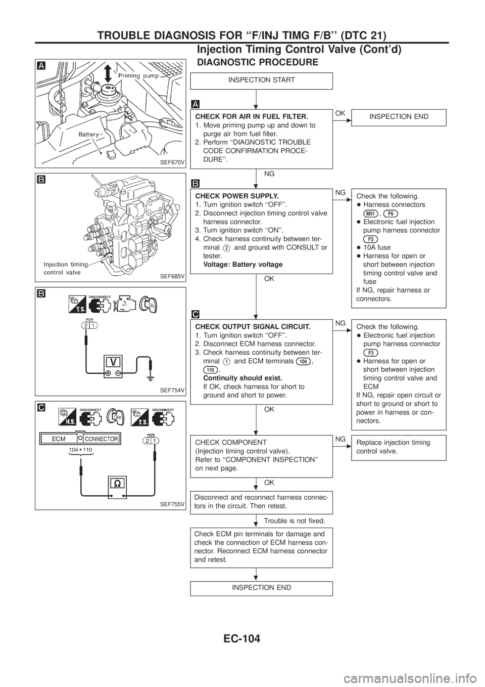
DIAGNOSTIC PROCEDURE
INSPECTION START
CHECK FOR AIR IN FUEL FILTER.
1. Move priming pump up and down to
purge air from fuel ®lter.
2. Perform ``DIAGNOSTIC TROUBLE
CODE CONFIRMATION PROCE-
DURE''.
NG
cOK
INSPECTION END
CHECK POWER SUPPLY.
1. Turn ignition switch ``OFF''.
2. Disconnect injection timing control valve
harness connector.
3. Turn ignition switch ``ON''.
4. Check harness continuity between ter-
minal
V2and ground with CONSULT or
tester.
Voltage: Battery voltage
OK
cNG
Check the following.
+Harness connectors
M51,F6
+Electronic fuel injection
pump harness connector
F3
+10A fuse
+Harness for open or
short between injection
timing control valve and
fuse
If NG, repair harness or
connectors.
CHECK OUTPUT SIGNAL CIRCUIT.
1. Turn ignition switch ``OFF''.
2. Disconnect ECM harness connector.
3. Check harness continuity between ter-
minal
V1and ECM terminals104,
11 0.
Continuity should exist.
If OK, check harness for short to
ground and short to power.
OK
cNG
Check the following.
+Electronic fuel injection
pump harness connector
F3
+Harness for open or
short between injection
timing control valve and
ECM
If NG, repair open circuit or
short to ground or short to
power in harness or con-
nectors.
CHECK COMPONENT
(Injection timing control valve).
Refer to ``COMPONENT INSPECTION''
on next page.
OK
cNG
Replace injection timing
control valve.
Disconnect and reconnect harness connec-
tors in the circuit. Then retest.
Trouble is not ®xed.
Check ECM pin terminals for damage and
check the connection of ECM harness con-
nector. Reconnect ECM harness connector
and retest.
INSPECTION END
SEF670V
SEF685V
SEF754V
SEF755V
.
.
.
.
.
.
.
TROUBLE DIAGNOSIS FOR ``F/INJ TIMG F/B'' (DTC 21)
Injection Timing Control Valve (Cont'd)
EC-104
Page 260 of 1226
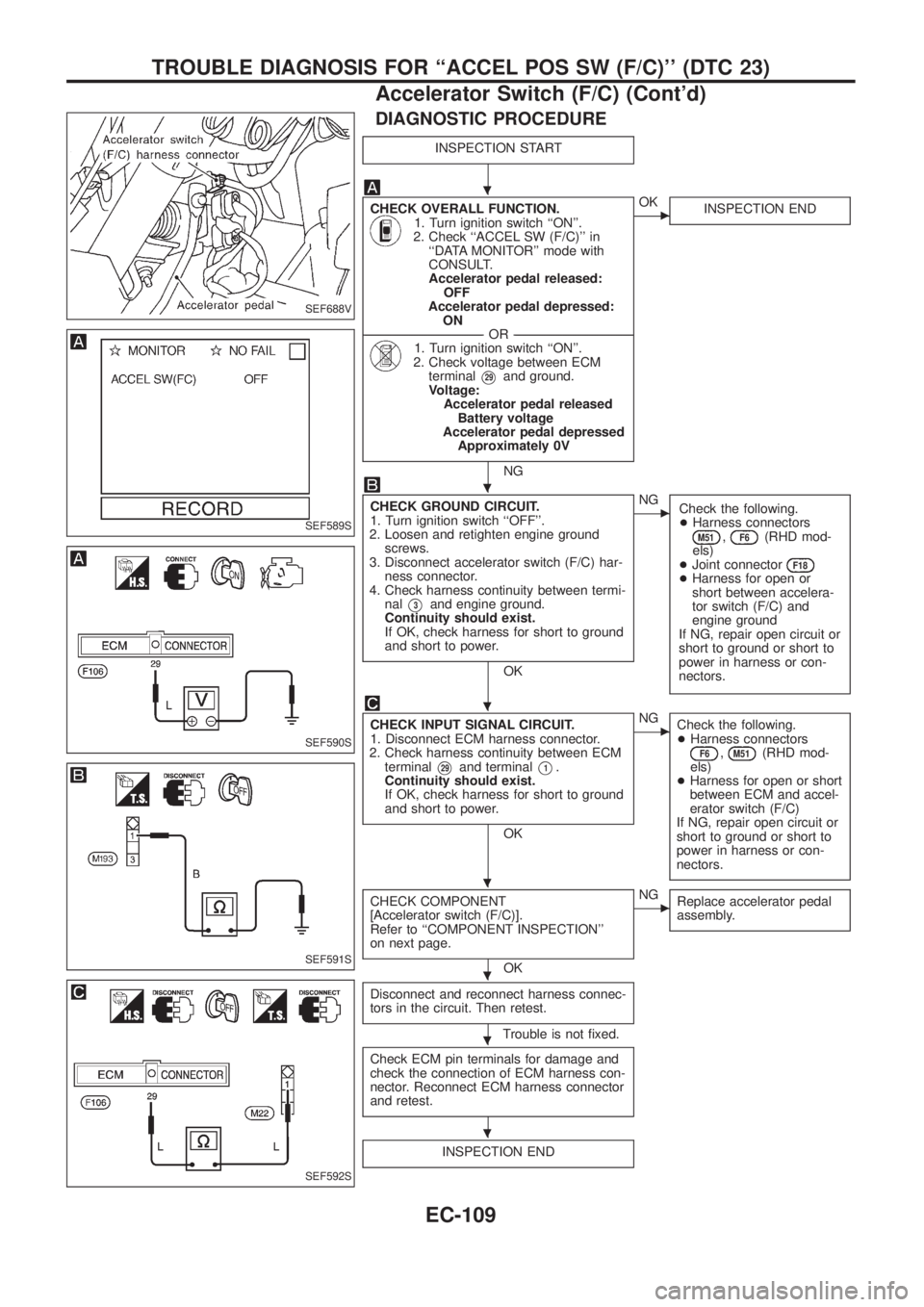
DIAGNOSTIC PROCEDURE
INSPECTION START
CHECK OVERALL FUNCTION.1. Turn ignition switch ``ON''.
2. Check ``ACCEL SW (F/C)'' in
``DATA MONITOR'' mode with
CONSULT.
Accelerator pedal released:
OFF
Accelerator pedal depressed:
ON
--------------------------------------------------------------------------------------------------------------------------------------OR--------------------------------------------------------------------------------------------------------------------------------------
1. Turn ignition switch ``ON''.
2. Check voltage between ECM
terminal
V29and ground.
Voltage:
Accelerator pedal released
Battery voltage
Accelerator pedal depressed
Approximately 0V
NG
cOK
INSPECTION END
CHECK GROUND CIRCUIT.
1. Turn ignition switch ``OFF''.
2. Loosen and retighten engine ground
screws.
3. Disconnect accelerator switch (F/C) har-
ness connector.
4. Check harness continuity between termi-
nal
V3and engine ground.
Continuity should exist.
If OK, check harness for short to ground
and short to power.
OK
cNG
Check the following.
+Harness connectors
M51,F6(RHD mod-
els)
+Joint connector
F18+Harness for open or
short between accelera-
tor switch (F/C) and
engine ground
If NG, repair open circuit or
short to ground or short to
power in harness or con-
nectors.
CHECK INPUT SIGNAL CIRCUIT.
1. Disconnect ECM harness connector.
2. Check harness continuity between ECM
terminal
V29and terminalV1.
Continuity should exist.
If OK, check harness for short to ground
and short to power.
OK
cNG
Check the following.
+Harness connectors
F6,M51(RHD mod-
els)
+Harness for open or short
between ECM and accel-
erator switch (F/C)
If NG, repair open circuit or
short to ground or short to
power in harness or con-
nectors.
CHECK COMPONENT
[Accelerator switch (F/C)].
Refer to ``COMPONENT INSPECTION''
on next page.
OK
cNG
Replace accelerator pedal
assembly.
Disconnect and reconnect harness connec-
tors in the circuit. Then retest.
Trouble is not ®xed.
Check ECM pin terminals for damage and
check the connection of ECM harness con-
nector. Reconnect ECM harness connector
and retest.
INSPECTION END
SEF688V
SEF589S
SEF590S
SEF591S
SEF592S
.
.
.
.
.
.
.
TROUBLE DIAGNOSIS FOR ``ACCEL POS SW (F/C)'' (DTC 23)
Accelerator Switch (F/C) (Cont'd)
EC-109
Page 262 of 1226
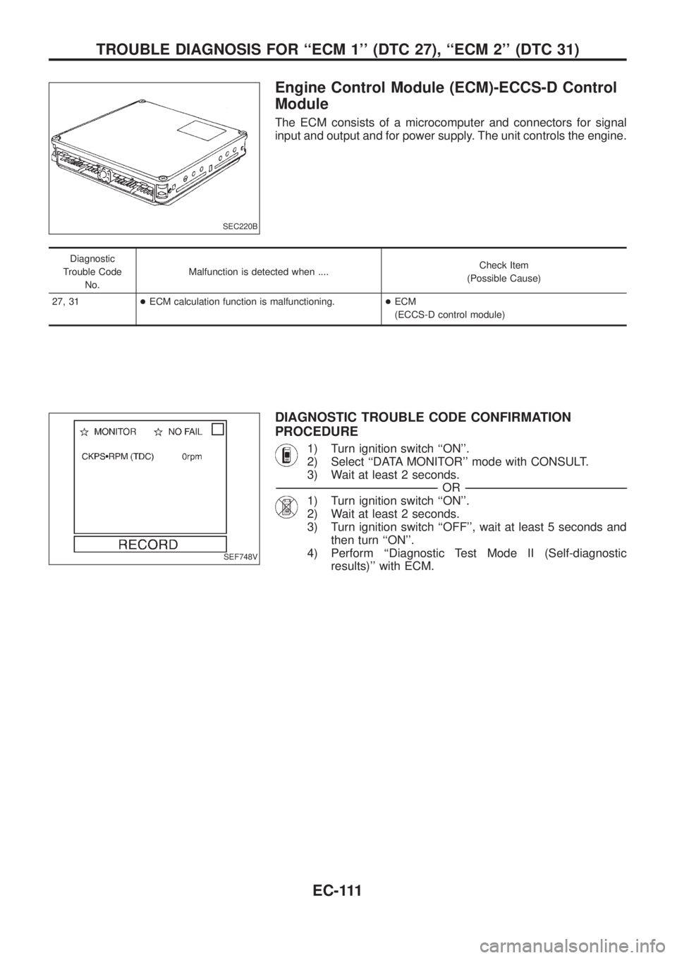
Engine Control Module (ECM)-ECCS-D Control
Module
The ECM consists of a microcomputer and connectors for signal
input and output and for power supply. The unit controls the engine.
Diagnostic
Trouble Code
No.Malfunction is detected when ....Check Item
(Possible Cause)
27, 31+ECM calculation function is malfunctioning.+ECM
(ECCS-D control module)
DIAGNOSTIC TROUBLE CODE CONFIRMATION
PROCEDURE
1) Turn ignition switch ``ON''.
2) Select ``DATA MONITOR'' mode with CONSULT.
3) Wait at least 2 seconds.
-------------------------------------------------------------------------------------------------------------------------------------------------------------------------------------------------------------------------------------------------------OR-------------------------------------------------------------------------------------------------------------------------------------------------------------------------------------------------------------------------------------------------------
1) Turn ignition switch ``ON''.
2) Wait at least 2 seconds.
3) Turn ignition switch ``OFF'', wait at least 5 seconds and
then turn ``ON''.
4) Perform ``Diagnostic Test Mode II (Self-diagnostic
results)'' with ECM.
SEC220B
SEF748V
TROUBLE DIAGNOSIS FOR ``ECM 1'' (DTC 27), ``ECM 2'' (DTC 31)
EC-111
Page 273 of 1226
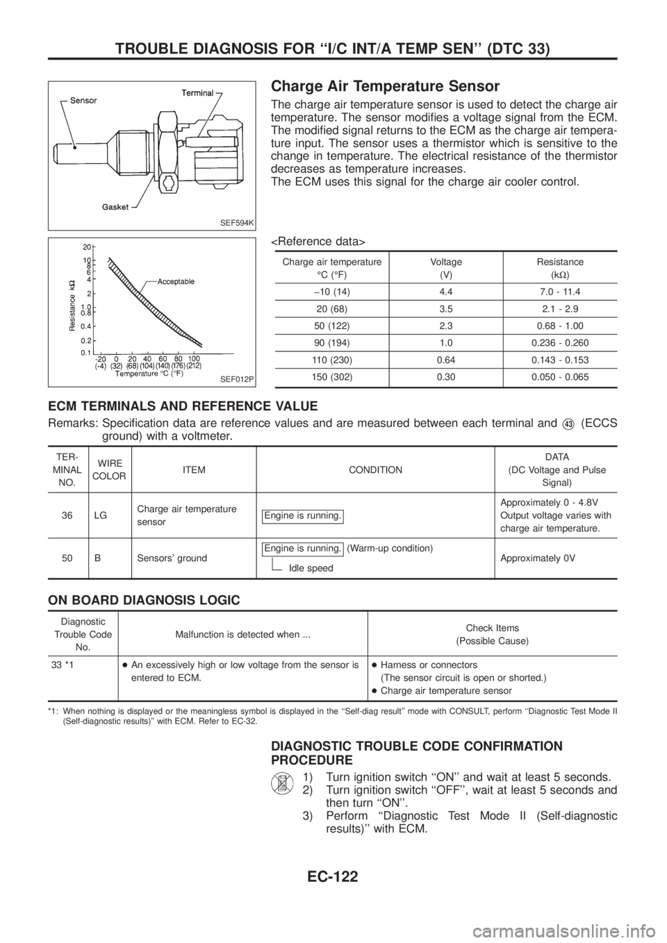
Charge Air Temperature Sensor
The charge air temperature sensor is used to detect the charge air
temperature. The sensor modi®es a voltage signal from the ECM.
The modi®ed signal returns to the ECM as the charge air tempera-
ture input. The sensor uses a thermistor which is sensitive to the
change in temperature. The electrical resistance of the thermistor
decreases as temperature increases.
The ECM uses this signal for the charge air cooler control.
Charge air temperatureÉC (ÉF) Voltage
(V) Resistance
(kW)
þ10 (14) 4.4 7.0 - 11.4 20 (68) 3.5 2.1 - 2.9
50 (122) 2.3 0.68 - 1.00
90 (194) 1.0 0.236 - 0.260
110 (230) 0.64 0.143 - 0.153
150 (302) 0.30 0.050 - 0.065
ECM TERMINALS AND REFERENCE VALUE
Remarks: Speci®cation data are reference values and are measured between each terminal andV43(ECCS
ground) with a voltmeter.
TER-
MINAL NO. WIRE
COLOR ITEM CONDITION DATA
(DC Voltage and Pulse Signal)
36 LG Charge air temperature
sensor Engine is running.
Approximatel
y 0 - 4.8V
Output voltage varies with
charge air temperature.
50 B Sensors' ground Engine is running.
(Warm-up condition)
Idle speed Approximately 0V
ON BOARD DIAGNOSIS LOGIC
Diagnostic
Trouble Code No. Malfunction is detected when ...
Check Items
(Possible Cause)
33 *1 +An excessively high or low voltage from the sensor is
entered to ECM. +
Harness or connectors
(The sensor circuit is open or shorted.)
+ Charge air temperature sensor
*1: When nothing is displayed or the meaningless symbol is displayed in the ``Self-diag result'' mode with CONSULT, perform ``Diagnostic Test Mode II
(Self-diagnostic results)'' with ECM. Refer to EC-32.
DIAGNOSTIC TROUBLE CODE CONFIRMATION
PROCEDURE
1) Turn ignition switch ``ON'' and wait at least 5 seconds.
2) Turn ignition switch ``OFF'', wait at least 5 seconds and then turn ``ON''.
3) Perform ``Diagnostic Test Mode II (Self-diagnostic results)'' with ECM.
SEF594K
SEF012P
TROUBLE DIAGNOSIS FOR ``I/C INT/A TEMP SEN'' (DTC 33)
EC-122
Page 280 of 1226
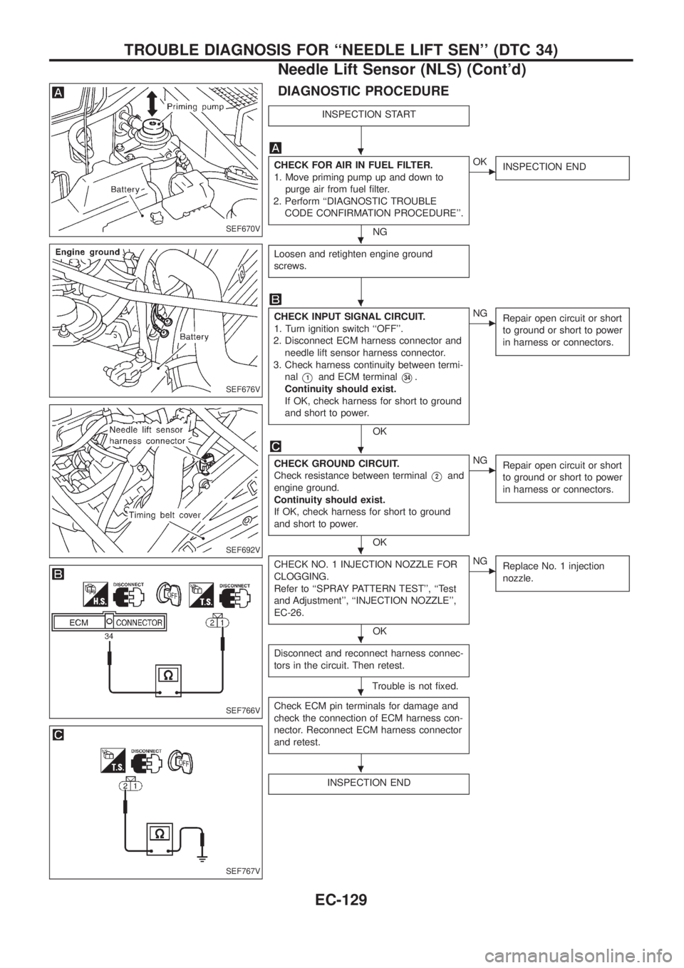
DIAGNOSTIC PROCEDURE
INSPECTION START
CHECK FOR AIR IN FUEL FILTER.
1. Move priming pump up and down to
purge air from fuel ®lter.
2. Perform ``DIAGNOSTIC TROUBLE
CODE CONFIRMATION PROCEDURE''.
NG
cOK
INSPECTION END
Loosen and retighten engine ground
screws.
CHECK INPUT SIGNAL CIRCUIT.
1. Turn ignition switch ``OFF''.
2. Disconnect ECM harness connector and
needle lift sensor harness connector.
3. Check harness continuity between termi-
nal
V1and ECM terminalV34.
Continuity should exist.
If OK, check harness for short to ground
and short to power.
OK
cNG
Repair open circuit or short
to ground or short to power
in harness or connectors.
CHECK GROUND CIRCUIT.
Check resistance between terminal
V2and
engine ground.
Continuity should exist.
If OK, check harness for short to ground
and short to power.
OK
cNG
Repair open circuit or short
to ground or short to power
in harness or connectors.
CHECK NO. 1 INJECTION NOZZLE FOR
CLOGGING.
Refer to ``SPRAY PATTERN TEST'', ``Test
and Adjustment'', ``INJECTION NOZZLE'',
EC-26.
OK
cNG
Replace No. 1 injection
nozzle.
Disconnect and reconnect harness connec-
tors in the circuit. Then retest.
Trouble is not ®xed.
Check ECM pin terminals for damage and
check the connection of ECM harness con-
nector. Reconnect ECM harness connector
and retest.
INSPECTION END
SEF670V
SEF676V
SEF692V
SEF766V
SEF767V
.
.
.
.
.
.
.
.
TROUBLE DIAGNOSIS FOR ``NEEDLE LIFT SEN'' (DTC 34)
Needle Lift Sensor (NLS) (Cont'd)
EC-129