Page 1112 of 1226

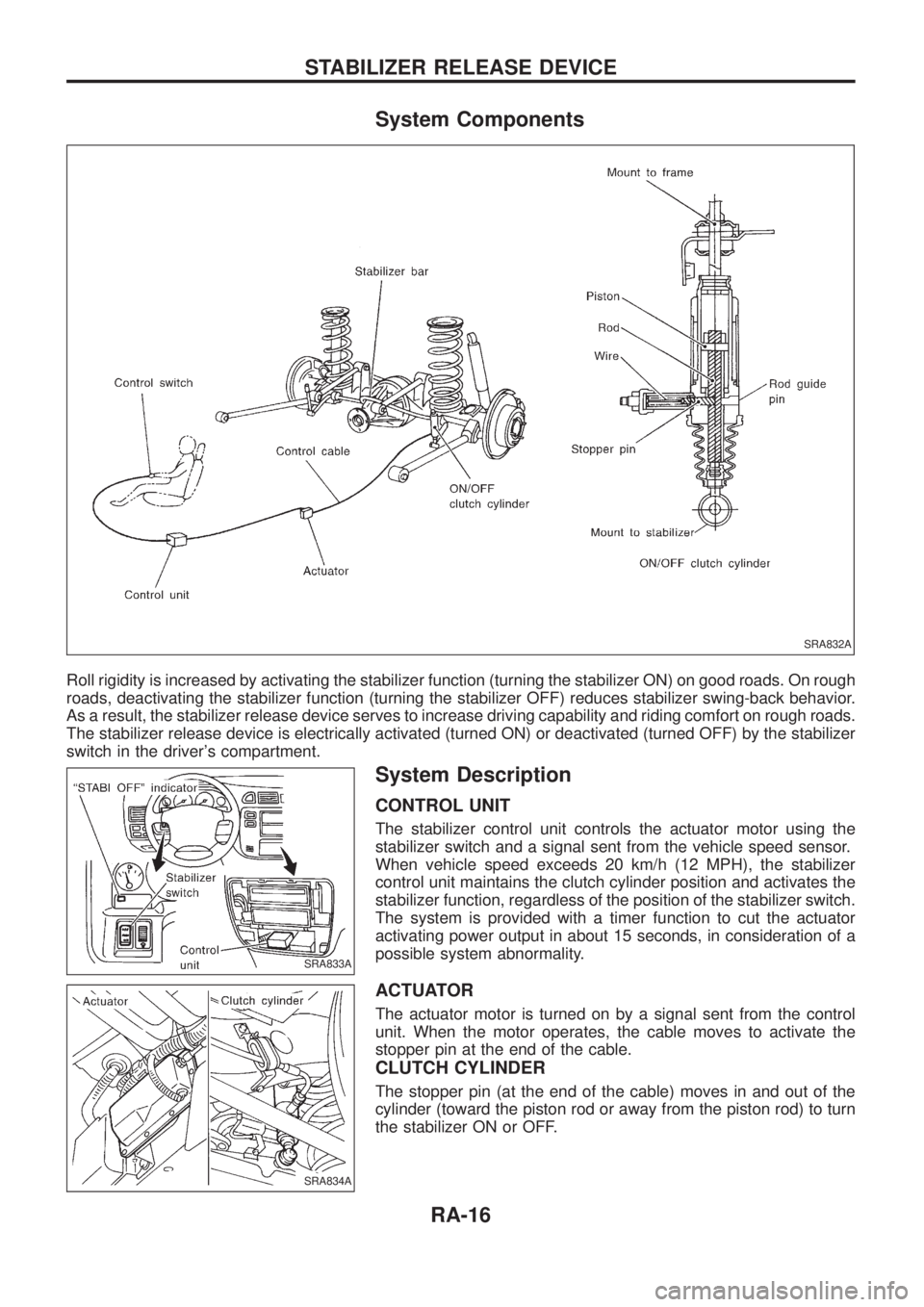
System Components
Roll rigidity is increased by activating the stabilizer function (turning the stabilizer ON) on good roads. On rough
roads, deactivating the stabilizer function (turning the stabilizer OFF) reduces stabilizer swing-back behavior.
As a result, the stabilizer release device serves to increase driving capability and riding comfort on rough roads.
The stabilizer release device is electrically activated (turned ON) or deactivated (turned OFF) by the stabilizer
switch in the driver's compartment.
System Description
CONTROL UNIT
The stabilizer control unit controls the actuator motor using the
stabilizer switch and a signal sent from the vehicle speed sensor.
When vehicle speed exceeds 20 km/h (12 MPH), the stabilizer
control unit maintains the clutch cylinder position and activates the
stabilizer function, regardless of the position of the stabilizer switch.
The system is provided with a timer function to cut the actuator
activating power output in about 15 seconds, in consideration of a
possible system abnormality.
ACTUATOR
The actuator motor is turned on by a signal sent from the control
unit. When the motor operates, the cable moves to activate the
stopper pin at the end of the cable.
CLUTCH CYLINDER
The stopper pin (at the end of the cable) moves in and out of the
cylinder (toward the piston rod or away from the piston rod) to turn
the stabilizer ON or OFF.
SRA832A
SRA833A
SRA834A
STABILIZER RELEASE DEVICE
RA-16
Page 1161 of 1226

Trouble Diagnoses without CONSULT
DIAGNOSTIC PROCEDURE 6
Inspecting SRS malfunctioning parts by using ``AIR BAG''
warning lamp Ð Diagnosis mode
NOTE:
SRS will not enter Diagnosis mode if no malfunction is
detected in User mode.
1. Open driver's door.
2. Turn ignition switch from ``OFF'' to ``ON''.
3. Press driver's door switch at least 5 times within 7 seconds
after turning ignition switch ``ON''.
SRS is now in Diagnosis mode.
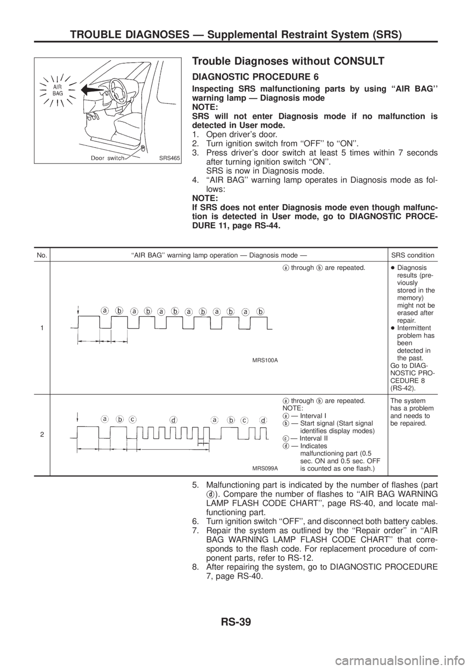
4. ``AIR BAG'' warning lamp operates in Diagnosis mode as fol-
lows:
NOTE:
If SRS does not enter Diagnosis mode even though malfunc-
tion is detected in User mode, go to DIAGNOSTIC PROCE-
DURE 11, page RS-44.
No. ``AIR BAG'' warning lamp operation Ð Diagnosis mode Ð SRS condition
1
MRS100A
jathroughjbare repeated.+Diagnosis
results (pre-
viously
stored in the
memory)
might not be
erased after
repair.
+Intermittent
problem has
been
detected in
the past.
Go to DIAG-
NOSTIC PRO-
CEDURE 8
(RS-42).
2
MRS099A
jathroughjbare repeated.
NOTE:
j
aÐ Interval I
jbÐ Start signal (Start signal
identi®es display modes)
j
cÐ Interval II
jdÐ Indicates
malfunctioning part (0.5
sec. ON and 0.5 sec. OFF
is counted as one ¯ash.)The system
has a problem
and needs to
be repaired.
5. Malfunctioning part is indicated by the number of ¯ashes (part
j
d). Compare the number of ¯ashes to ``AIR BAG WARNING
LAMP FLASH CODE CHART'', page RS-40, and locate mal-
functioning part.
6. Turn ignition switch ``OFF'', and disconnect both battery cables.
7. Repair the system as outlined by the ``Repair order'' in ``AIR
BAG WARNING LAMP FLASH CODE CHART'' that corre-
sponds to the ¯ash code. For replacement procedure of com-
ponent parts, refer to RS-12.
8. After repairing the system, go to DIAGNOSTIC PROCEDURE
7, page RS-40.
SRS465
TROUBLE DIAGNOSES Ð Supplemental Restraint System (SRS)
RS-39
Page 1163 of 1226

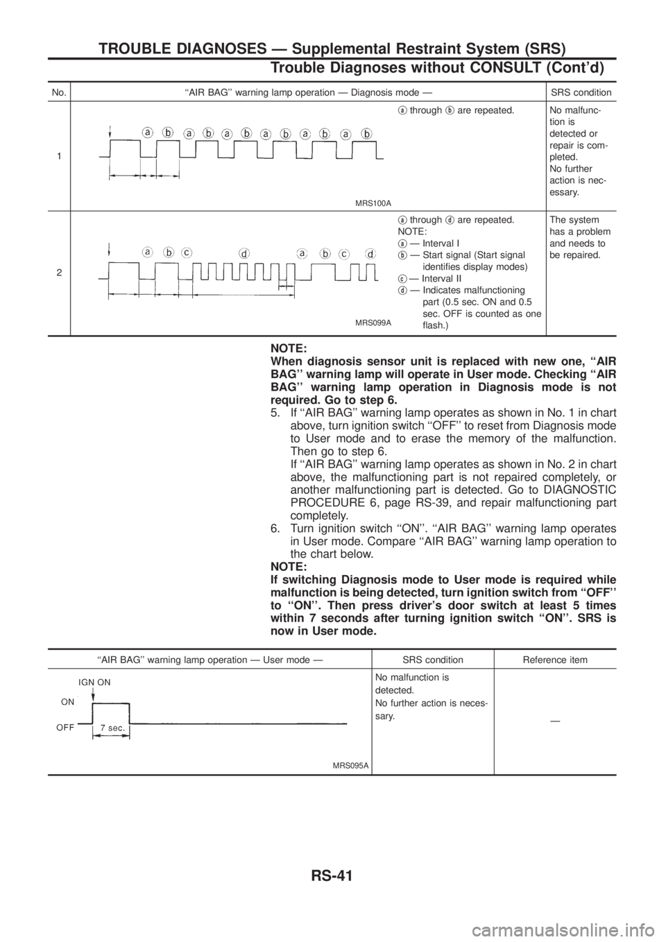
No. ``AIR BAG'' warning lamp operation Ð Diagnosis mode Ð SRS condition
1
MRS100A
jathroughjbare repeated. No malfunc-
tion is
detected or
repair is com-
pleted.
No further
action is nec-
essary.
2
MRS099A
jathroughjdare repeated.
NOTE:
j
aÐ Interval I
jbÐ Start signal (Start signal
identi®es display modes)
j
cÐ Interval II
jdÐ Indicates malfunctioning
part (0.5 sec. ON and 0.5
sec. OFF is counted as one
¯ash.)The system
has a problem
and needs to
be repaired.
NOTE:
When diagnosis sensor unit is replaced with new one, ``AIR
BAG'' warning lamp will operate in User mode. Checking ``AIR
BAG'' warning lamp operation in Diagnosis mode is not
required. Go to step 6.
5. If ``AIR BAG'' warning lamp operates as shown in No. 1 in chart
above, turn ignition switch ``OFF'' to reset from Diagnosis mode
to User mode and to erase the memory of the malfunction.
Then go to step 6.
If ``AIR BAG'' warning lamp operates as shown in No. 2 in chart
above, the malfunctioning part is not repaired completely, or
another malfunctioning part is detected. Go to DIAGNOSTIC
PROCEDURE 6, page RS-39, and repair malfunctioning part
completely.
6. Turn ignition switch ``ON''. ``AIR BAG'' warning lamp operates
in User mode. Compare ``AIR BAG'' warning lamp operation to
the chart below.
NOTE:
If switching Diagnosis mode to User mode is required while
malfunction is being detected, turn ignition switch from ``OFF''
to ``ON''. Then press driver's door switch at least 5 times
within 7 seconds after turning ignition switch ``ON''. SRS is
now in User mode.
``AIR BAG'' warning lamp operation Ð User mode Ð SRS condition Reference item
MRS095A
No malfunction is
detected.
No further action is neces-
sary.
Ð
TROUBLE DIAGNOSES Ð Supplemental Restraint System (SRS)
Trouble Diagnoses without CONSULT (Cont'd)
RS-41