2006 NISSAN PATROL parking
[x] Cancel search: parkingPage 786 of 1226
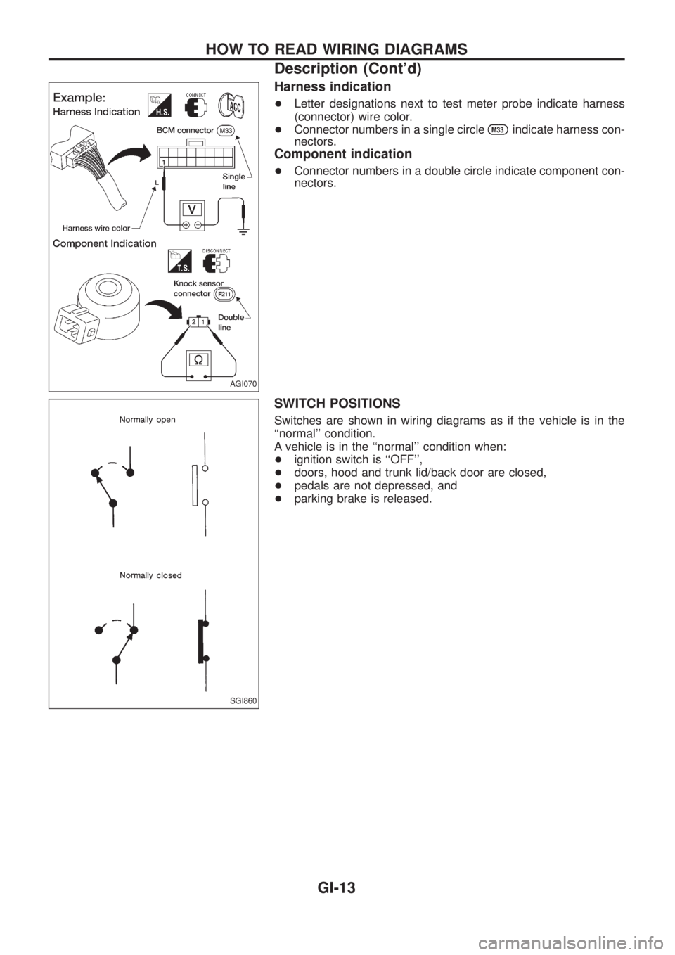
Harness indication
+Letter designations next to test meter probe indicate harness
(connector) wire color.
+Connector numbers in a single circle
M33indicate harness con-
nectors.
Component indication
+Connector numbers in a double circle indicate component con-
nectors.
SWITCH POSITIONS
Switches are shown in wiring diagrams as if the vehicle is in the
``normal'' condition.
A vehicle is in the ``normal'' condition when:
+ignition switch is ``OFF'',
+doors, hood and trunk lid/back door are closed,
+pedals are not depressed, and
+parking brake is released.
AGI070
SGI860
HOW TO READ WIRING DIAGRAMS
Description (Cont'd)
GI-13
Page 805 of 1226
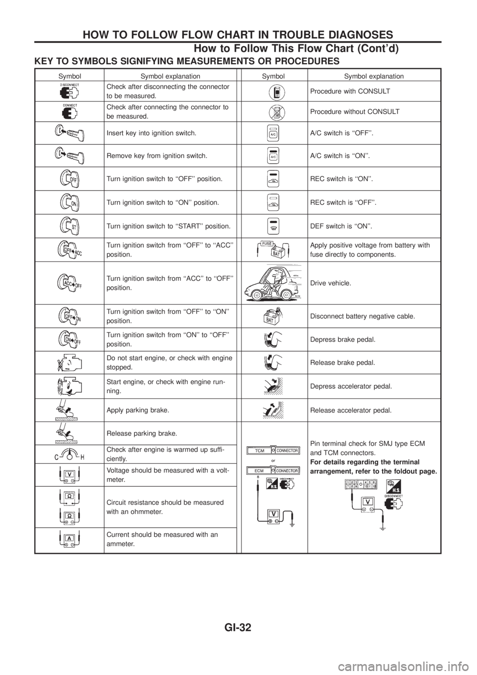
KEY TO SYMBOLS SIGNIFYING MEASUREMENTS OR PROCEDURES
Symbol Symbol explanation Symbol Symbol explanation
Check after disconnecting the connector
to be measured.Procedure with CONSULT
Check after connecting the connector to
be measured.Procedure without CONSULT
Insert key into ignition switch.A/C switch is ``OFF''.
Remove key from ignition switch.A/C switch is ``ON''.
Turn ignition switch to ``OFF'' position.REC switch is ``ON''.
Turn ignition switch to ``ON'' position.REC switch is ``OFF''.
Turn ignition switch to ``START'' position.DEF switch is ``ON''.
Turn ignition switch from ``OFF'' to ``ACC''
position.Apply positive voltage from battery with
fuse directly to components.
Turn ignition switch from ``ACC'' to ``OFF''
position.Drive vehicle.
Turn ignition switch from ``OFF'' to ``ON''
position.Disconnect battery negative cable.
Turn ignition switch from ``ON'' to ``OFF''
position.Depress brake pedal.
Do not start engine, or check with engine
stopped.Release brake pedal.
Start engine, or check with engine run-
ning.Depress accelerator pedal.
Apply parking brake.Release accelerator pedal.
Release parking brake.
Pin terminal check for SMJ type ECM
and TCM connectors.
For details regarding the terminal
arrangement, refer to the foldout page.Check after engine is warmed up suffi-
ciently.
Voltage should be measured with a volt-
meter.
Circuit resistance should be measured
with an ohmmeter.
Current should be measured with an
ammeter.
HOW TO FOLLOW FLOW CHART IN TROUBLE DIAGNOSES
How to Follow This Flow Chart (Cont'd)
GI-32
Page 814 of 1226
Tow Truck Towing
CAUTION:
+All applicable local laws regarding the towing operation
must be obeyed.
+It is necessary to use proper towing equipment to avoid
possible damage to the vehicle during a towing operation.
+Attach safety chains for all towing.
+When towing, make sure that the transmission, steering
system and power train are in good order. If any unit is
damaged, a dolly must be used.
+When towing with the front wheels on the ground:
Turn the ignition key to the ``OFF'' position and secure the
steering wheel in a straight-ahead position with a rope or
similar device. Never place the ignition key in the ``LOCK''
position. This will result in damage to the steering lock
mechanism.
+When towing manual transmission models with the rear
wheels on the ground:
Release the parking brake and move the gearshift lever to
neutral (``N'' position).
+For 4-wheel drive models:
Set the manual-lock free-running hubs to the free position and
2-way lock free-running hubs to the auto position. (See
``
Transfer case shifting procedures for 4-wheel drive
vehicles'' in ``Starting and driving'' section.) Move the transfer
case shift lever into the ``2H'' position and the transmission shift
lever into the neutral (``N'') position.
Do not shift the transfer lever to the ``4L'' position. This will
cause damage to the transmission.
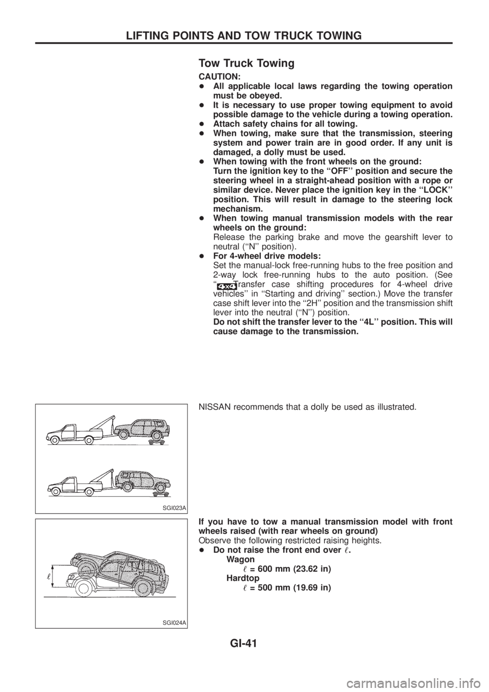
NISSAN recommends that a dolly be used as illustrated.
If you have to tow a manual transmission model with front
wheels raised (with rear wheels on ground)
Observe the following restricted raising heights.
+Do not raise the front end over!.
Wagon
!= 600 mm (23.62 in)
Hardtop
!= 500 mm (19.69 in)
SGI023A
SGI024A
LIFTING POINTS AND TOW TRUCK TOWING
GI-41
Page 979 of 1226
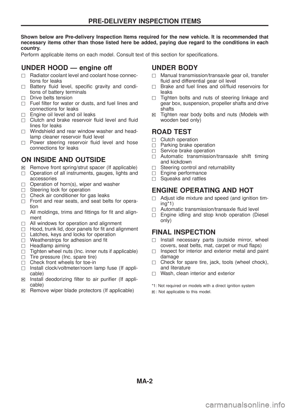
Shown below are Pre-delivery Inspection Items required for the new vehicle. It is recommended that
necessary items other than those listed here be added, paying due regard to the conditions in each
country.
Perform applicable items on each model. Consult text of this section for speci®cations.
UNDER HOOD Ð engine off
hRadiator coolant level and coolant hose connec-
tions for leaks
hBattery ¯uid level, speci®c gravity and condi-
tions of battery terminals
hDrive belts tension
hFuel ®lter for water or dusts, and fuel lines and
connections for leaks
hEngine oil level and oil leaks
hClutch and brake reservoir ¯uid level and ¯uid
lines for leaks
hWindshield and rear window washer and head-
lamp cleaner reservoir ¯uid level
hPower steering reservoir ¯uid level and hose
connections for leaks
ON INSIDE AND OUTSIDE
hXRemove front spring/strut spacer (If applicable)
hOperation of all instruments, gauges, lights and
accessories
hOperation of horn(s), wiper and washer
hSteering lock for operation
hCheck air conditioner for gas leaks
hFront and rear seats, and seat belts for opera-
tion
hAll moldings, trims and ®ttings for ®t and align-
ment
hAll windows for operation and alignment
hHood, trunk lid, door panels for ®t and alignment
hLatches, keys and locks for operation
hWeatherstrips for adhesion and ®t
hHeadlamp aiming
hTighten wheel nuts (Inc. inner nuts if applicable)
hTire pressure (Inc. spare tire)
hCheck front wheels for toe-in
hInstall clock/voltmeter/room lamp fuse (If appli-
cable)
h
XInstall deodorizing ®lter to air puri®er (If appli-
cable)
h
XRemove wiper blade protectors (If applicable)
UNDER BODY
hManual transmission/transaxle gear oil, transfer
¯uid and differential gear oil level
hBrake and fuel lines and oil/¯uid reservoirs for
leaks
hTighten bolts and nuts of steering linkage and
gear box, suspension, propeller shafts and drive
shafts
h
XTighten rear body bolts and nuts (Models with
wooden bed only)
ROAD TEST
hClutch operation
hParking brake operation
hService brake operation
hAutomatic transmission/transaxle shift timing
and kickdown
hSteering control and returnability
hEngine performance
hSqueaks and rattles
ENGINE OPERATING AND HOT
hAdjust idle mixture and speed (and ignition tim-
ing*1)
hAutomatic transmission/transaxle ¯uid level
hEngine idling and stop knob operation (Diesel
only)
FINAL INSPECTION
hInstall necessary parts (outside mirror, wheel
covers, seat belts, mat, carpet or mud ¯aps)
hInspect for interior and exterior metal and paint
damage
hCheck for spare tire, jack, tools (wheel chock),
and literature
hWash, clean interior and exterior
*1: Not required on models with a direct ignition system
h
X: Not applicable to this model.
PRE-DELIVERY INSPECTION ITEMS
MA-2
Page 980 of 1226
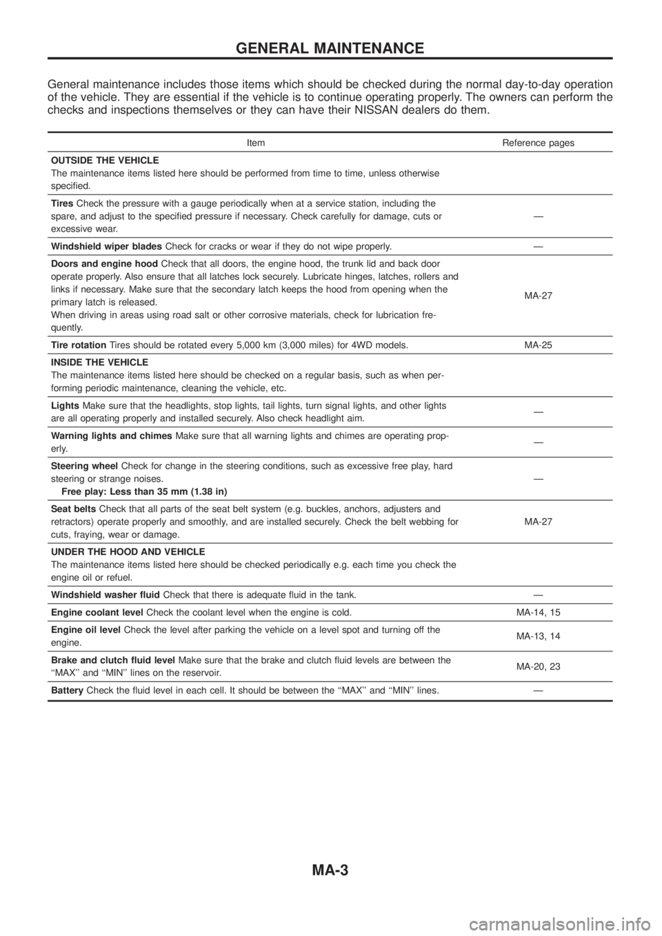
General maintenance includes those items which should be checked during the normal day-to-day operation
of the vehicle. They are essential if the vehicle is to continue operating properly. The owners can perform the
checks and inspections themselves or they can have their NISSAN dealers do them.
Item Reference pages
OUTSIDE THE VEHICLE
The maintenance items listed here should be performed from time to time, unless otherwise
speci®ed.
TiresCheck the pressure with a gauge periodically when at a service station, including the
spare, and adjust to the speci®ed pressure if necessary. Check carefully for damage, cuts or
excessive wear.Ð
Windshield wiper bladesCheck for cracks or wear if they do not wipe properly. Ð
Doors and engine hoodCheck that all doors, the engine hood, the trunk lid and back door
operate properly. Also ensure that all latches lock securely. Lubricate hinges, latches, rollers and
links if necessary. Make sure that the secondary latch keeps the hood from opening when the
primary latch is released.
When driving in areas using road salt or other corrosive materials, check for lubrication fre-
quently.MA-27
Tire rotationTires should be rotated every 5,000 km (3,000 miles) for 4WD models. MA-25
INSIDE THE VEHICLE
The maintenance items listed here should be checked on a regular basis, such as when per-
forming periodic maintenance, cleaning the vehicle, etc.
LightsMake sure that the headlights, stop lights, tail lights, turn signal lights, and other lights
are all operating properly and installed securely. Also check headlight aim.Ð
Warning lights and chimesMake sure that all warning lights and chimes are operating prop-
erly.Ð
Steering wheelCheck for change in the steering conditions, such as excessive free play, hard
steering or strange noises.
Free play: Less than 35 mm (1.38 in)Ð
Seat beltsCheck that all parts of the seat belt system (e.g. buckles, anchors, adjusters and
retractors) operate properly and smoothly, and are installed securely. Check the belt webbing for
cuts, fraying, wear or damage.MA-27
UNDER THE HOOD AND VEHICLE
The maintenance items listed here should be checked periodically e.g. each time you check the
engine oil or refuel.
Windshield washer ¯uidCheck that there is adequate ¯uid in the tank. Ð
Engine coolant levelCheck the coolant level when the engine is cold. MA-14, 15
Engine oil levelCheck the level after parking the vehicle on a level spot and turning off the
engine.MA-13, 14
Brake and clutch ¯uid levelMake sure that the brake and clutch ¯uid levels are between the
``MAX'' and ``MIN'' lines on the reservoir.MA-20, 23
BatteryCheck the ¯uid level in each cell. It should be between the ``MAX'' and ``MIN'' lines. Ð
GENERAL MAINTENANCE
MA-3
Page 983 of 1226
![NISSAN PATROL 2006 Service Manual Chassis and Body Services
Annual driving distance below 30,000 km (18,000 miles)
Abbreviations: R = Replace, I = Inspect, and correct or replace as necessary, L = Lubricate,T=Tighten.
[ ]: At the spec NISSAN PATROL 2006 Service Manual Chassis and Body Services
Annual driving distance below 30,000 km (18,000 miles)
Abbreviations: R = Replace, I = Inspect, and correct or replace as necessary, L = Lubricate,T=Tighten.
[ ]: At the spec](/manual-img/5/57368/w960_57368-982.png)
Chassis and Body Services
Annual driving distance below 30,000 km (18,000 miles)
Abbreviations: R = Replace, I = Inspect, and correct or replace as necessary, L = Lubricate,T=Tighten.
[ ]: At the speci®ed mileage only
MAINTENANCE OPERATIONMAINTENANCE INTERVAL
Reference
page Perform either at number of kilometers (miles) or months,
whichever comes ®rst.km x 1,000 10 20 30 40 50 60 70 80 90
(Miles x 1,000) (6) (12) (18) (24) (30) (36) (42) (48) (54)
Months 6 12 18 24 30 36 42 48 54
CHASSIS AND BODY Underhood and under vehicle
Brake & clutch ¯uid (For level & leaks).I I I I MA-23, 20
Brake ¯uid.R R MA-24
Brake booster vacuum hoses, connections & check valve I I MA-24
Power steering ¯uid & lines (For level & leaks) I I I I MA-26
Brake & clutch systemsI I I I MA-24, 20
Manual transmission oil (For leaks) I I I I MA-20
Manual transmission oil[R] MA-20
Transfer ¯uidI I R I MA-21
Limited slip differential (LSD) gear oil (For level & leaks).*1 I I R I MA-22
Steering gear & linkage, axle & suspension parts, propeller shaft & exhaust system.I I I I MA-26, 20 *2
Greasing points of propeller shaftLLLLMA-21
Drive shafts & steering damper.IIII *3
Body mounting bolts & nutsTTTT *4
Outside and Inside
Wheel alignment (If necessary, rotate & balance wheels) I I I I MA-25, *5
Brake pads, discs & other brake components.I I I I MA-24
Front wheel bearing grease I R I R MA-22
Axle joint in knuckle ¯angeL L MA-23
Free running hub greaseI I I I MA-23
Headlamp aimingIIII *6
Foot brake, parking brake & clutch (For free play, stroke & operation) I I I I *7
Ventilation air ®lterRRR*8
Body corrosionAnnually MA-28
Air bag systemSee NOTE (1) *9
NOTE: (1) Inspect after 10 years, then every 2 years.
(2) Maintenance items with ``.'' should be performed more frequently according to ``Maintenance Under Severe Driv-
ing Conditions''.
*1: Including differential gear with differential lock
*2: ``Front Axle and Front Suspension Parts'' in FA section, ``Rear Axle and Rear Suspension Parts'' in RA section
*3: ``FRONT AXLE Ð Drive Shaft'' in FA section
*4: ``CAB BODY'' in BT section
*5: ``Front Wheel Alignment'' in FA section
*6: ``Aiming Adjustment'' in EL section
*7: ``Brake Pedal and Bracket'' in BR section, ``Adjusting Clutch Pedal'' in CL section
*8: ``Ventilation air ®lter'' in HA section
*9: ``Maintenance Items'' in RS section
PERIODIC MAINTENANCE
MA-6
Page 984 of 1226
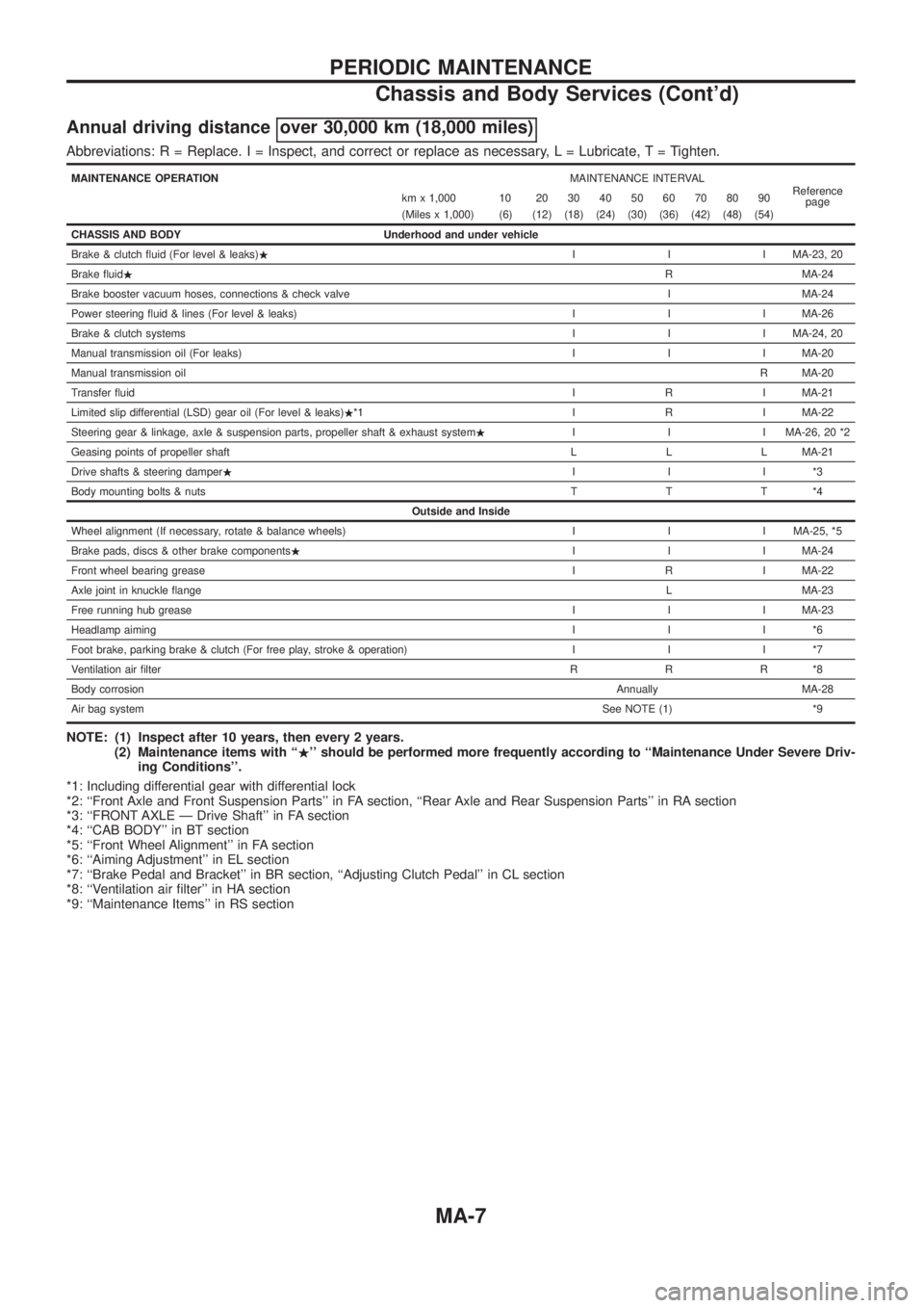
Annual driving distance over 30,000 km (18,000 miles)
Abbreviations: R = Replace. I = Inspect, and correct or replace as necessary, L = Lubricate,T=Tighten.
MAINTENANCE OPERATIONMAINTENANCE INTERVAL
Reference
page km x 1,000 10 20 30 40 50 60 70 80 90
(Miles x 1,000) (6) (12) (18) (24) (30) (36) (42) (48) (54)
CHASSIS AND BODY Underhood and under vehicle
Brake & clutch ¯uid (For level & leaks).I I I MA-23, 20
Brake ¯uid.R MA-24
Brake booster vacuum hoses, connections & check valve I MA-24
Power steering ¯uid & lines (For level & leaks) I I I MA-26
Brake & clutch systemsI I I MA-24, 20
Manual transmission oil (For leaks) I I I MA-20
Manual transmission oilR MA-20
Transfer ¯uidI R I MA-21
Limited slip differential (LSD) gear oil (For level & leaks).*1 I R I MA-22
Steering gear & linkage, axle & suspension parts, propeller shaft & exhaust system.I I I MA-26, 20 *2
Geasing points of propeller shaft L L L MA-21
Drive shafts & steering damper.III*3
Body mounting bolts & nutsTTT*4
Outside and Inside
Wheel alignment (If necessary, rotate & balance wheels) I I I MA-25, *5
Brake pads, discs & other brake components.I I I MA-24
Front wheel bearing greaseI R I MA-22
Axle joint in knuckle ¯angeL MA-23
Free running hub greaseI I I MA-23
Headlamp aimingIII*6
Foot brake, parking brake & clutch (For free play, stroke & operation) I I I *7
Ventilation air ®lterRRR*8
Body corrosionAnnually MA-28
Air bag systemSee NOTE (1) *9
NOTE: (1) Inspect after 10 years, then every 2 years.
(2) Maintenance items with ``.'' should be performed more frequently according to ``Maintenance Under Severe Driv-
ing Conditions''.
*1: Including differential gear with differential lock
*2: ``Front Axle and Front Suspension Parts'' in FA section, ``Rear Axle and Rear Suspension Parts'' in RA section
*3: ``FRONT AXLE Ð Drive Shaft'' in FA section
*4: ``CAB BODY'' in BT section
*5: ``Front Wheel Alignment'' in FA section
*6: ``Aiming Adjustment'' in EL section
*7: ``Brake Pedal and Bracket'' in BR section, ``Adjusting Clutch Pedal'' in CL section
*8: ``Ventilation air ®lter'' in HA section
*9: ``Maintenance Items'' in RS section
PERIODIC MAINTENANCE
Chassis and Body Services (Cont'd)
MA-7
Page 1001 of 1226
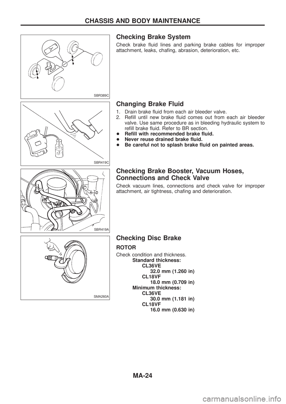
Checking Brake System
Check brake ¯uid lines and parking brake cables for improper
attachment, leaks, cha®ng, abrasion, deterioration, etc.
Changing Brake Fluid
1. Drain brake ¯uid from each air bleeder valve.
2. Re®ll until new brake ¯uid comes out from each air bleeder
valve. Use same procedure as in bleeding hydraulic system to
re®ll brake ¯uid. Refer to BR section.
+Re®ll with recommended brake ¯uid.
+Never reuse drained brake ¯uid.
+Be careful not to splash brake ¯uid on painted areas.
Checking Brake Booster, Vacuum Hoses,
Connections and Check Valve
Check vacuum lines, connections and check valve for improper
attachment, air tightness, cha®ng and deterioration.
Checking Disc Brake
ROTOR
Check condition and thickness.
Standard thickness:
CL36VE
32.0 mm (1.260 in)
CL18VF
18.0 mm (0.709 in)
Minimum thickness:
CL36VE
30.0 mm (1.181 in)
CL18VF
16.0 mm (0.630 in)
SBR389C
SBR419C
SBR419A
SMA260A
CHASSIS AND BODY MAINTENANCE
MA-24