2006 NISSAN PATROL engine control system
[x] Cancel search: engine control systemPage 169 of 1226
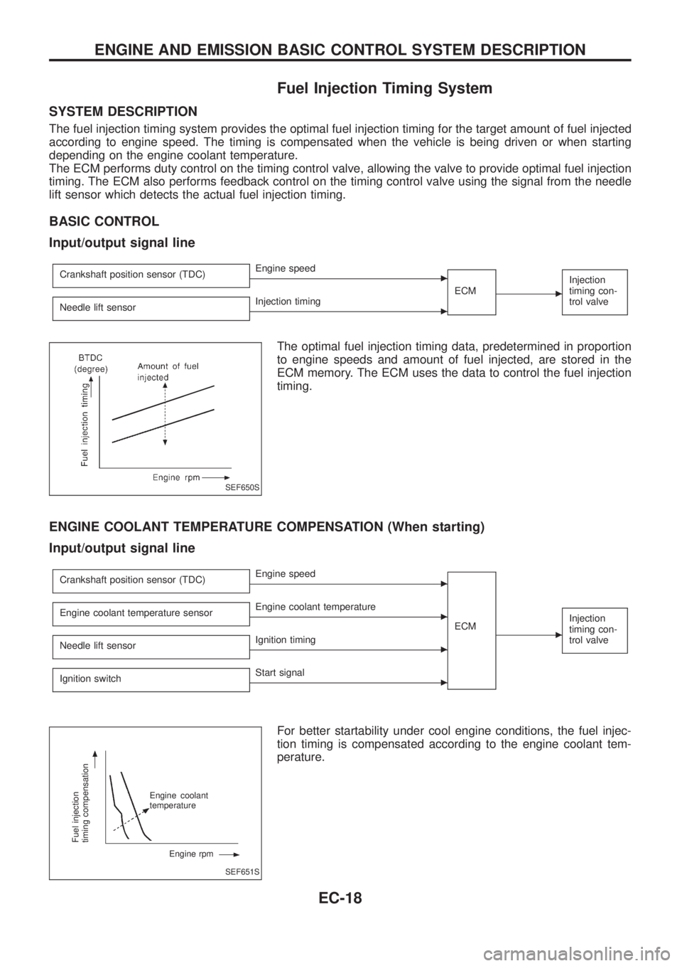
Fuel Injection Timing System
SYSTEM DESCRIPTION
The fuel injection timing system provides the optimal fuel injection timing for the target amount of fuel injected
according to engine speed. The timing is compensated when the vehicle is being driven or when starting
depending on the engine coolant temperature.
The ECM performs duty control on the timing control valve, allowing the valve to provide optimal fuel injection
timing. The ECM also performs feedback control on the timing control valve using the signal from the needle
lift sensor which detects the actual fuel injection timing.
BASIC CONTROL
Input/output signal line
Crankshaft position sensor (TDC)cEngine speed
ECM
c
Injection
timing con-
trol valve
Needle lift sensorcInjection timing
The optimal fuel injection timing data, predetermined in proportion
to engine speeds and amount of fuel injected, are stored in the
ECM memory. The ECM uses the data to control the fuel injection
timing.
ENGINE COOLANT TEMPERATURE COMPENSATION (When starting)
Input/output signal line
Crankshaft position sensor (TDC)cEngine speed
ECM
c
Injection
timing con-
trol valveEngine coolant temperature sensorcEngine coolant temperature
Needle lift sensor
cIgnition timing
Ignition switch
cStart signal
For better startability under cool engine conditions, the fuel injec-
tion timing is compensated according to the engine coolant tem-
perature.
SEF650S
SEF651S
Fuel injection
timing compensation
Engine coolant
temperature
Engine rpm
ENGINE AND EMISSION BASIC CONTROL SYSTEM DESCRIPTION
EC-18
Page 170 of 1226
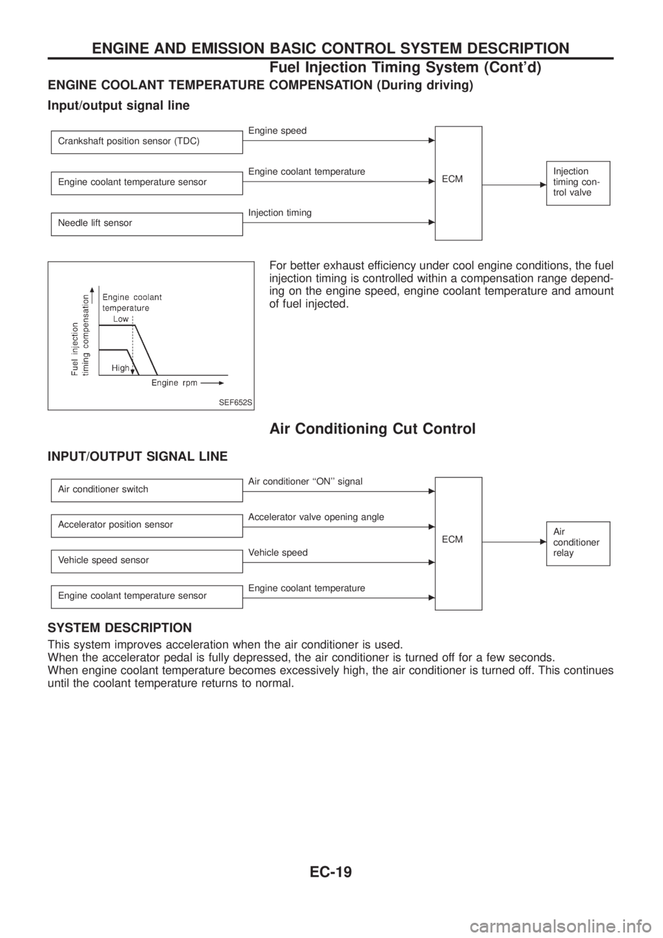
ENGINE COOLANT TEMPERATURE COMPENSATION (During driving)
Input/output signal line
Crankshaft position sensor (TDC)cEngine speed
ECM
c
Injection
timing con-
trol valveEngine coolant temperature sensorcEngine coolant temperature
Needle lift sensor
cInjection timing
For better exhaust efficiency under cool engine conditions, the fuel
injection timing is controlled within a compensation range depend-
ing on the engine speed, engine coolant temperature and amount
of fuel injected.
Air Conditioning Cut Control
INPUT/OUTPUT SIGNAL LINE
Air conditioner switchcAir conditioner ``ON'' signal
ECM
cAir
conditioner
relayAccelerator position sensorcAccelerator valve opening angle
Vehicle speed sensor
cVehicle speed
Engine coolant temperature sensor
cEngine coolant temperature
SYSTEM DESCRIPTION
This system improves acceleration when the air conditioner is used.
When the accelerator pedal is fully depressed, the air conditioner is turned off for a few seconds.
When engine coolant temperature becomes excessively high, the air conditioner is turned off. This continues
until the coolant temperature returns to normal.
SEF652S
ENGINE AND EMISSION BASIC CONTROL SYSTEM DESCRIPTION
Fuel Injection Timing System (Cont'd)
EC-19
Page 171 of 1226
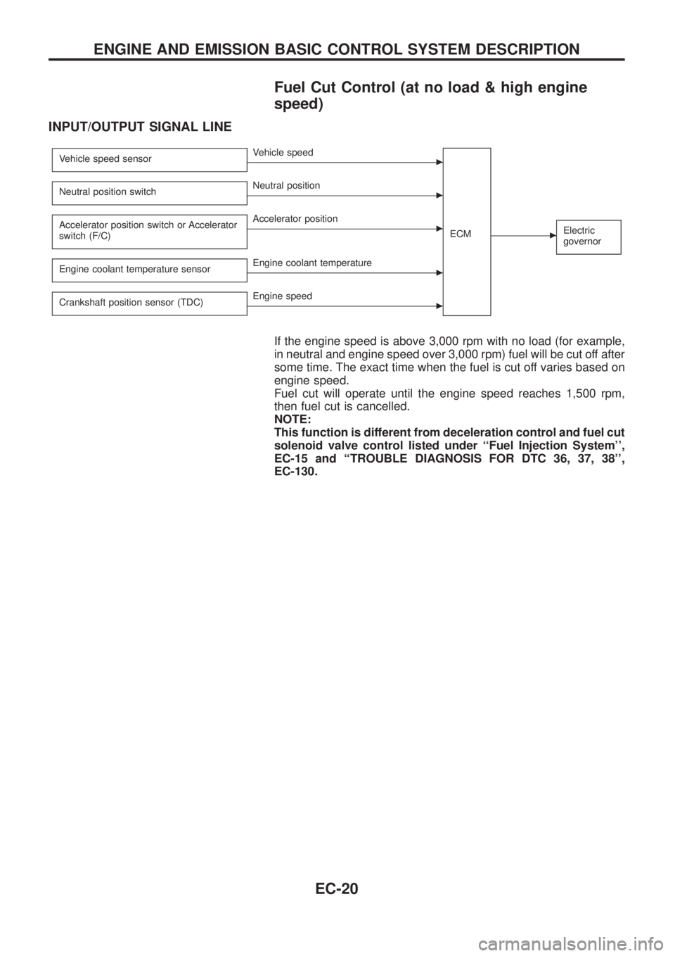
Fuel Cut Control (at no load & high engine
speed)
INPUT/OUTPUT SIGNAL LINE
Vehicle speed sensorcVehicle speed
ECM
cElectric
governor
Neutral position switchcNeutral position
Accelerator position switch or Accelerator
switch (F/C)
cAccelerator position
Engine coolant temperature sensor
cEngine coolant temperature
Crankshaft position sensor (TDC)
cEngine speed
If the engine speed is above 3,000 rpm with no load (for example,
in neutral and engine speed over 3,000 rpm) fuel will be cut off after
some time. The exact time when the fuel is cut off varies based on
engine speed.
Fuel cut will operate until the engine speed reaches 1,500 rpm,
then fuel cut is cancelled.
NOTE:
This function is different from deceleration control and fuel cut
solenoid valve control listed under ``Fuel Injection System'',
EC-15 and ``TROUBLE DIAGNOSIS FOR DTC 36, 37, 38'',
EC-130.
ENGINE AND EMISSION BASIC CONTROL SYSTEM DESCRIPTION
EC-20
Page 181 of 1226

DTC and MIL Detection Logic
When a malfunction is detected for the ®rst time, the malfunction (DTC) is stored in the ECM memory.
The MIL will light up each time the ECM detects malfunction. However, if the same malfunction is experienced
in two consecutive driving patterns and the engine is still running, the MIL will stay lit up. For diagnostic items
causing the MIL to light up, refer to ``DIAGNOSTIC TROUBLE CODE INDEX'', EC-1.
Diagnostic Trouble Code (DTC)
HOW TO READ DTC
The diagnostic trouble code can be read by the following methods.
1. The number of blinks of the malfunction indicator lamp in the Diagnostic Test Mode II (Self-Diagnostic
Results) Examples: 11, 13, 14, etc.
These DTCs are controlled by NISSAN.
2. CONSULT Examples: ``CAM POS SEN (PUMP)'', etc.
+Output of the trouble code means that the indicated circuit has a malfunction. However, in the Mode
II it does not indicate whether the malfunction is still occurring or occurred in the past and returned
to normal.
CONSULT can identify them. Therefore, using CONSULT (if available) is recommended.
HOW TO ERASE DTC
The diagnostic trouble code can be erased by the following methods.
Selecting ``ERASE'' in the ``SELF-DIAG RESULTS'' mode with CONSULT.
Changing the diagnostic test mode from Diagnostic Test Mode II to Mode I. (Refer to EC-32.)
+If the battery terminal is disconnected, the diagnostic trouble code will be lost within 24 hours.
+When you erase the DTC, using CONSULT is easier and quicker than switching the diagnostic test
modes.
HOW TO ERASE DTC (With CONSULT)
1. If the ignition switch stays ``ON'' after repair work, be sure to turn ignition switch ``OFF'' once. Wait at least
5 seconds and then turn it ``ON'' (Engine stopped) again.
2. Turn CONSULT ``ON'' and touch ``ENGINE''.
3. Touch ``SELF-DIAG RESULTS''.
4. Touch ``ERASE''. (The DTC in the ECM will be erased.)
HOW TO ERASE DTC (No Tools)
1. If the ignition switch stays ``ON'' after repair work, be sure to turn ignition switch ``OFF'' once. Wait at least
5 seconds and then turn it ``ON'' again.
2. Change the diagnostic test mode from Mode II to Mode I. (Refer to EC-32.)
SEF691S
ON BOARD DIAGNOSTIC SYSTEM DESCRIPTION
EC-30
Page 188 of 1226
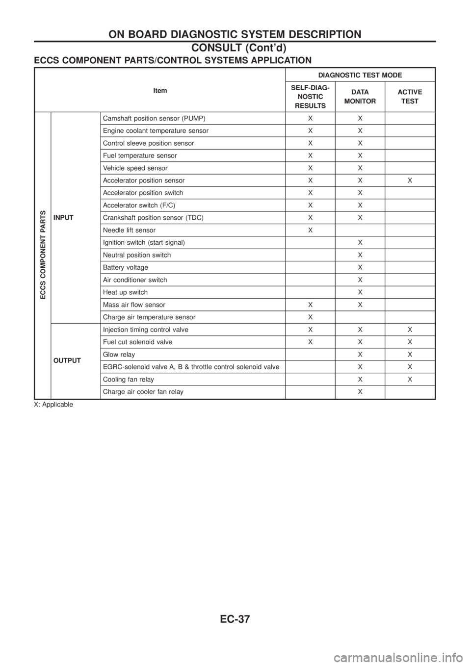
ECCS COMPONENT PARTS/CONTROL SYSTEMS APPLICATION
ItemDIAGNOSTIC TEST MODE
SELF-DIAG-
NOSTIC
RESULTSDATA
MONITORACTIVE
TEST
ECCS COMPONENT PARTS
INPUTCamshaft position sensor (PUMP) X X
Engine coolant temperature sensor X X
Control sleeve position sensor X X
Fuel temperature sensor X X
Vehicle speed sensor X X
Accelerator position sensor X X X
Accelerator position switch X X
Accelerator switch (F/C) X X
Crankshaft position sensor (TDC) X X
Needle lift sensor X
Ignition switch (start signal) X
Neutral position switch X
Battery voltage X
Air conditioner switch X
Heat up switch X
Mass air ¯ow sensor X X
Charge air temperature sensor X
OUTPUTInjection timing control valve X X X
Fuel cut solenoid valve X X X
Glow relayXX
EGRC-solenoid valve A, B & throttle control solenoid valve X X
Cooling fan relay X X
Charge air cooler fan relay X
X: Applicable
ON BOARD DIAGNOSTIC SYSTEM DESCRIPTION
CONSULT (Cont'd)
EC-37
Page 189 of 1226
![NISSAN PATROL 2006 Service Manual SELF-DIAGNOSTIC MODE
Regarding items detected in ``SELF-DIAG RESULTS mode, refer to ``DIAGNOSTIC TROUBLE CODE
INDEX, EC-1.
DATA MONITOR MODE
Monitored item
[Unit]ECM
input
signalsMain
signalsDescr NISSAN PATROL 2006 Service Manual SELF-DIAGNOSTIC MODE
Regarding items detected in ``SELF-DIAG RESULTS mode, refer to ``DIAGNOSTIC TROUBLE CODE
INDEX, EC-1.
DATA MONITOR MODE
Monitored item
[Unit]ECM
input
signalsMain
signalsDescr](/manual-img/5/57368/w960_57368-188.png)
SELF-DIAGNOSTIC MODE
Regarding items detected in ``SELF-DIAG RESULTS'' mode, refer to ``DIAGNOSTIC TROUBLE CODE
INDEX'', EC-1.
DATA MONITOR MODE
Monitored item
[Unit]ECM
input
signalsMain
signalsDescription Remarks
CKPSzRPM
(TDC) [rpm]
jj
+The engine speed computed from the
crankshaft position sensor (TDC) signal
is displayed.
CKPSzRPM
(REF) [rpm]
jj
+The engine speed [determined by the
time between pulses from the crankshaft
position sensor (TDC) signal] is dis-
played.
CMPSzRPM -
PUMP [rpm]
jj
+The engine speed computed from the
camshaft position sensor (PUMP) signal
is displayed.
COOLAN TEMP/S
[ÉC] or [ÉF]
jj
+The engine coolant temperature (deter-
mined by the signal voltage of the engine
coolant temperature sensor) is displayed.+When the engine coolant temperature
sensor is open or short-circuited, ECM
enters fail-safe mode. The engine cool-
ant temperature determined by the ECM
is displayed.
VHCL SPEED SE
[km/h] or [mph]
jj+The vehicle speed computed from the
vehicle speed sensor signal is displayed.
FUEL TEMP SEN
[ÉC] or [ÉF]
jj
+The fuel temperature (determined by the
signal voltage of the fuel temperature
sensor) is displayed.
ACCEL POS SEN [V]
jj+The accelerator position sensor signal
voltage is displayed.
FULL ACCEL SW
[ON/OFF]
jj+Indicates [ON/OFF] condition from the
accelerator position switch signal.
ACCEL SW (FC)
[OPEN/CLOSE]
jj+Indicates [OPEN/CLOSE] condition from
the accelerator switch (FC) signal.
OFF ACCEL SW
[ON/OFF]
jj+Indicates [ON/OFF] condition from the
accelerator position switch signal.
C/SLEEV POS/S [V]
jj+The control sleeve position sensor signal
voltage is displayed.
BATTERY VOLT [V]
jj+The power supply voltage of ECM is dis-
played.
P/N POSI SW
[ON/OFF]
jj+Indicates [ON/OFF] condition from the
park/neutral position switch signal.
START SIGNAL
[ON/OFF]
jj+Indicates [ON/OFF] condition from the
starter signal.+After starting the engine, [OFF] is dis-
played regardless of the starter signal.
NOTE:
Any monitored item that does not match the vehicle being diagnosed is deleted from the display automatically.
ON BOARD DIAGNOSTIC SYSTEM DESCRIPTION
CONSULT (Cont'd)
EC-38
Page 190 of 1226
![NISSAN PATROL 2006 Service Manual Monitored item
[Unit]ECM
input
signalsMain
signalsDescription Remarks
AIR COND SIG
[ON/OFF]
jj
+Indicates [ON/OFF] condition of the air
conditioner switch as determined by the
air conditioner signal.
NISSAN PATROL 2006 Service Manual Monitored item
[Unit]ECM
input
signalsMain
signalsDescription Remarks
AIR COND SIG
[ON/OFF]
jj
+Indicates [ON/OFF] condition of the air
conditioner switch as determined by the
air conditioner signal.](/manual-img/5/57368/w960_57368-189.png)
Monitored item
[Unit]ECM
input
signalsMain
signalsDescription Remarks
AIR COND SIG
[ON/OFF]
jj
+Indicates [ON/OFF] condition of the air
conditioner switch as determined by the
air conditioner signal.
IGN SW
[ON/OFF]
jj+Indicates [ON/OFF] condition from igni-
tion switch signal.
MAS AIR/FL SE [V]
jj+The signal voltage of the mass air ¯ow
sensor is displayed.+When the engine is stopped, a certain
value is indicated.
ACT INJ TIMG [É]
jj
+The actual injection timing angle deter-
mined by the ECM (an approximate
average angle between injection start
and end from TDC) is displayed.
INJ TIMG C/V [%]+Indicates the duty ratio of fuel injection
timing control valve.
DECELER F/CUT
[ON/OFF]
j
+Indicates [ON/OFF] condition from decel-
eration fuel cut signal.+When the accelerator pedal is released
quickly with engine speed at 3,000 rpm
or more, ``ON'' is displayed.
FUEL CUT S/V
[ON/OFF]
j
+The control condition of the fuel cut sole-
noid valve (determined by ECM accord-
ing to the input signal) is indicted.
+OFF ... Fuel cut solenoid valve is not
operating.
ON ... Fuel cut solenoid valve is operat-
ing.+When the fuel cut solenoid valve is not
operating, fuel is not supplied to injection
nozzles.
GLOW RLY [ON/OFF]
j
+The glow relay control condition (deter-
mined by ECM according to the input
signal) is displayed.
COOLING FAN
[LOW/HI/OFF]
j
+Indicates the control condition of the
cooling fans (determined by ECM
according to the input signal).
+LOW ... Operates at low speed.
HI ... Operates at high speed.
OFF ... Stopped.
I/C FAN RLY
[ON/OFF]
j
+Indicates the control condition of the
charge air cooler fan (determined by
ECM according to the input signals).
EGRC SOL/V A
[ON/OFF]+The control condition of the EGRC-sole-
noid valve A (determined by ECM
according to the input signal) is indi-
cated.
+OFF ... EGRC-solenoid valve A is not
operating.
ON ... EGRC-solenoid valve A is operat-
ing.
EGRC SOL/V B
[ON/OFF]+The control condition of the EGRC-sole-
noid valve B (determined by ECM
according to the input signal) is indi-
cated.
+OFF ... EGRC-solenoid valve B is not
operating.
ON ... EGRC-solenoid valve B is operat-
ing.
THROT RLY
[ON/OFF]+The control condition of the throttle con-
trol solenoid valve (determined by ECM
according to the input signal) is indi-
cated.
+OFF ... Throttle control solenoid valve is
not operating.
ON ... Throttle control solenoid valve is
operating.
ON BOARD DIAGNOSTIC SYSTEM DESCRIPTION
CONSULT (Cont'd)
EC-39
Page 193 of 1226
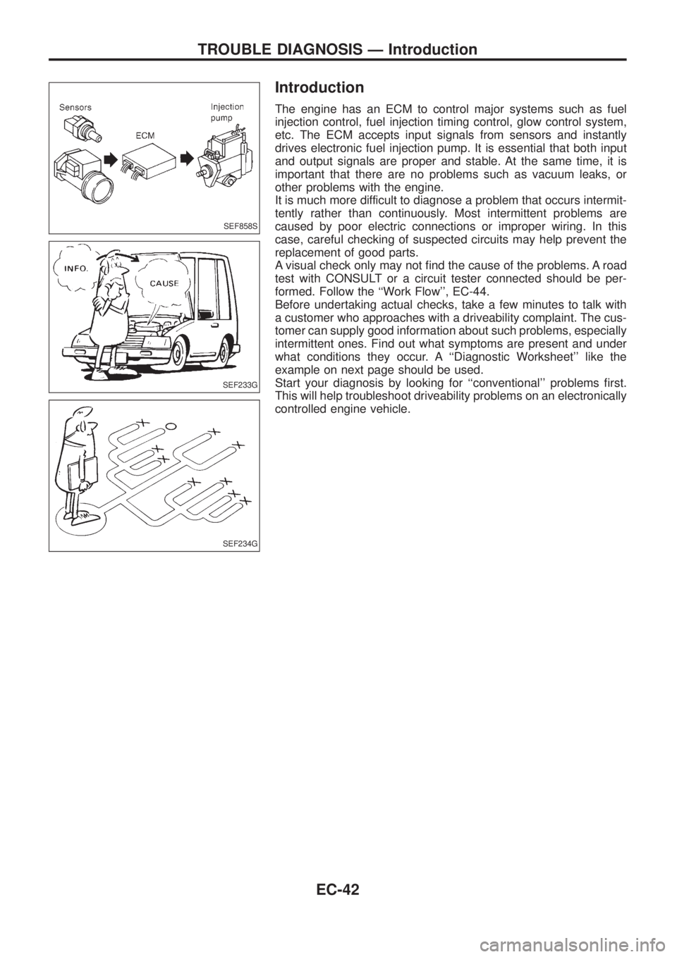
Introduction
The engine has an ECM to control major systems such as fuel
injection control, fuel injection timing control, glow control system,
etc. The ECM accepts input signals from sensors and instantly
drives electronic fuel injection pump. It is essential that both input
and output signals are proper and stable. At the same time, it is
important that there are no problems such as vacuum leaks, or
other problems with the engine.
It is much more difficult to diagnose a problem that occurs intermit-
tently rather than continuously. Most intermittent problems are
caused by poor electric connections or improper wiring. In this
case, careful checking of suspected circuits may help prevent the
replacement of good parts.
A visual check only may not ®nd the cause of the problems. A road
test with CONSULT or a circuit tester connected should be per-
formed. Follow the ``Work Flow'', EC-44.
Before undertaking actual checks, take a few minutes to talk with
a customer who approaches with a driveability complaint. The cus-
tomer can supply good information about such problems, especially
intermittent ones. Find out what symptoms are present and under
what conditions they occur. A ``Diagnostic Worksheet'' like the
example on next page should be used.
Start your diagnosis by looking for ``conventional'' problems ®rst.
This will help troubleshoot driveability problems on an electronically
controlled engine vehicle.
SEF858S
SEF233G
SEF234G
TROUBLE DIAGNOSIS Ð Introduction
EC-42