Page 585 of 1226

System Description
NATS has the following immobiliser functions:
+Since only NATS ignition keys, whose ID nos. have been registered into the ECM and IMMU of NATS,
allow the engine to run, operation of a stolen vehicle without a NATS registered key is prevented by NATS.
That is to say, NATS will immobilize the engine if someone tries to start it without the registered key of
NATS.
+Both of the originally supplied ignition key IDs have been NATS registered.
If requested by the vehicle owner, a maximum of four key IDs can be registered into the NATS compo-
nents.
+The NATS security indicator (NATS security ind.) blinks when the ignition switch is in ``OFF'' or ``ACC''
position. Therefore, NATS warns outsiders that the vehicle is equipped with the anti-theft system.
+When NATS detects trouble, the malfunction indicator lamp (MIL) blinks.
+NATS trouble diagnoses, system initialisation and additional registration of other NATS ignition key IDs
must be carried out using CONSULT hardware and CONSULT NATS software.
When NATS initialisation has been completed, the ID of the inserted ignition key is automatically NATS
registered. Then, if necessary, additional registration of other NATS ignition key IDs can be carried out.
Regarding the procedures of NATS initialisation and NATS ignition key ID registration, refer to CONSULT
operation manual, NATS.
+When servicing a malfunction of the NATS (indicated by ¯ashing of Malfunction Indicator Lamp)
or registering another NATS ignition key ID no., it may be necessary to re-register original key
identi®cation. Therefore, be sure to receive all keys from vehicle owner.
System Composition
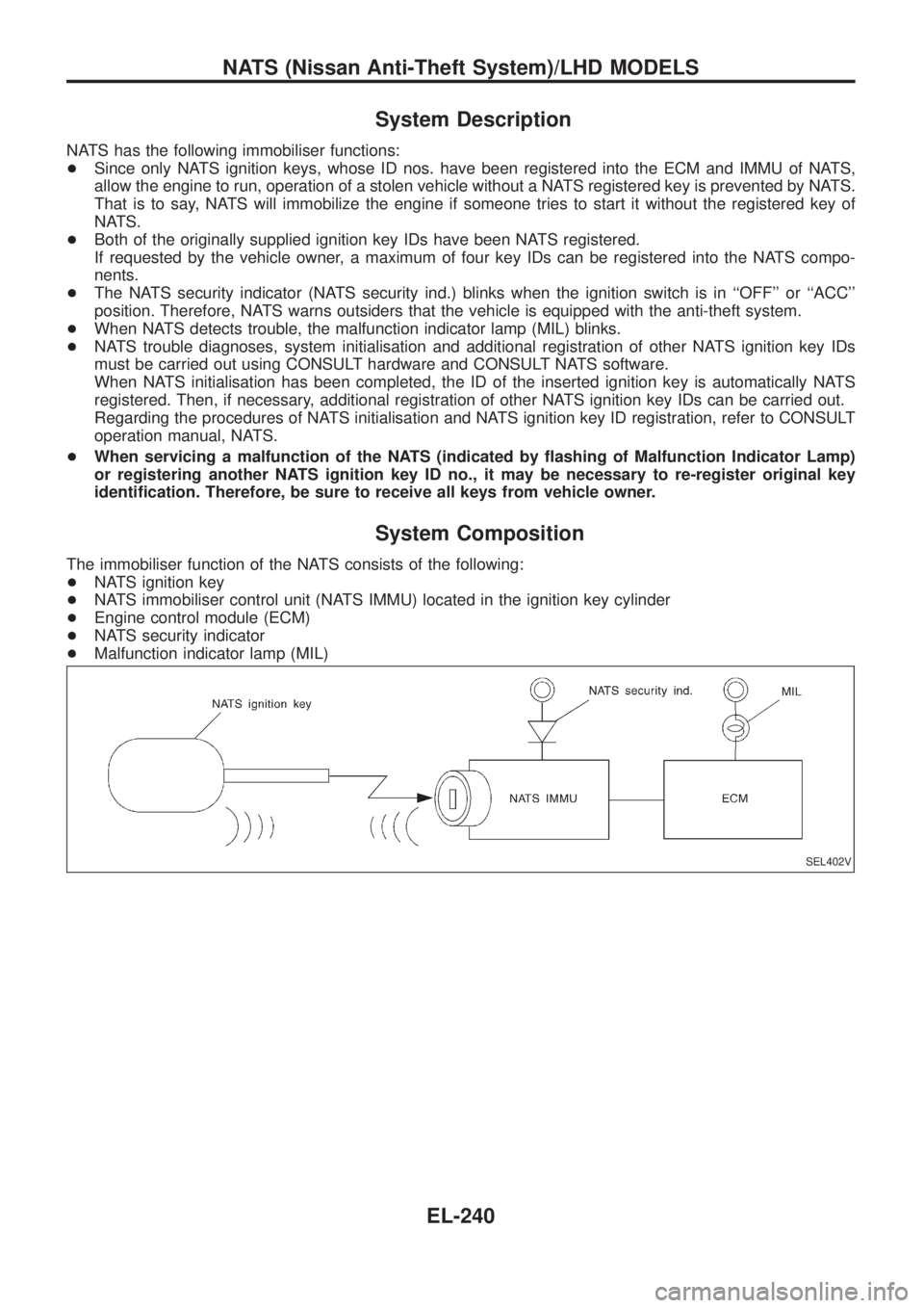
The immobiliser function of the NATS consists of the following:
+NATS ignition key
+NATS immobiliser control unit (NATS IMMU) located in the ignition key cylinder
+Engine control module (ECM)
+NATS security indicator
+Malfunction indicator lamp (MIL)
SEL402V
NATS (Nissan Anti-Theft System)/LHD MODELS
EL-240
Page 587 of 1226
CONSULT
CONSULT INSPECTION PROCEDURE
1. Turn off ignition switch.
2. Connect ``CONSULT'' to Data link connector for CONSULT.
3. Insert NATS program card into CONSULT.
: Program card
NATS-E940
4. Turn on ignition switch.
5. Touch ``START''.
6. Touch ``V.2.0 (GASOLINE)''.
NOTE: ``V.2.0 (GASOLINE)'' should be selected for electrically
controlled diesel and gasoline engines.
7. Perform each diagnostic test mode according to each service
procedure.
For further information, see the CONSULT Operation Manual,
NATS V2.0 (GASOLINE).
SEF532V
SEL327U
SEL328U
SEL329U
NATS (Nissan Anti-Theft System)/LHD MODELS
EL-242
Page 600 of 1226

System Description
NATS has the following immobiliser functions:
+Since only NATS ignition keys, whose ID nos. have been registered into the ECM and IMMU of NATS,
allow the engine to run, operation of a stolen vehicle without a NATS registered key is prevented by NATS.
That is to say, NATS will immobilize the engine if someone tries to start it without the registered key of
NATS.
+Both of the originally supplied ignition key IDs have been NATS registered.
If requested by the vehicle owner, a maximum of four key IDs can be registered into the NATS compo-
nents.
+The NATS security indicator (NATS security ind.) blinks when the ignition switch is in ``OFF'' or ``ACC''
position. Therefore, NATS warns outsiders that the vehicle is equipped with the anti-theft system.
+When NATS detects trouble, the malfunction indicator lamp (MIL) blinks.
+NATS trouble diagnoses, system initialisation and additional registration of other NATS ignition key IDs
must be carried out using CONSULT hardware and CONSULT NATS software.
When NATS initialisation has been completed, the ID of the inserted ignition key is automatically NATS
registered. Then, if necessary, additional registration of other NATS ignition key IDs can be carried out.
Regarding the procedures of NATS initialisation and NATS ignition key ID registration, refer to CONSULT
operation manual, NATS.
+When servicing a malfunction of the NATS (indicated by ¯ashing of Malfunction Indicator Lamp)
or registering another NATS ignition key ID no., it may be necessary to re-register original key
identi®cation. Therefore, be sure to receive all keys from vehicle owner.
System Composition
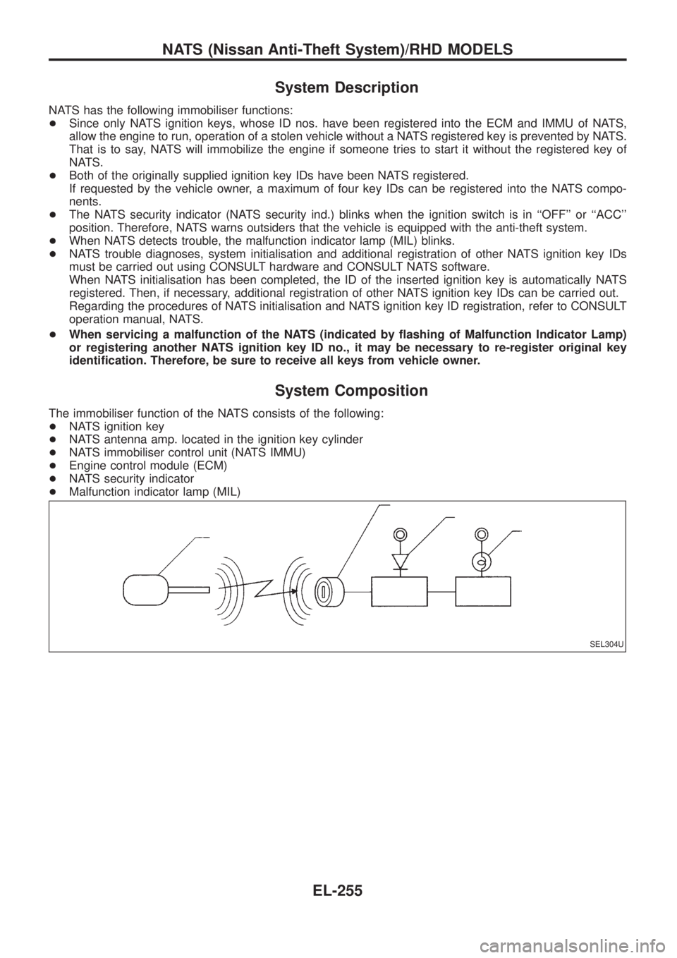
The immobiliser function of the NATS consists of the following:
+NATS ignition key
+NATS antenna amp. located in the ignition key cylinder
+NATS immobiliser control unit (NATS IMMU)
+Engine control module (ECM)
+NATS security indicator
+Malfunction indicator lamp (MIL)
SEL304U
NATS (Nissan Anti-Theft System)/RHD MODELS
EL-255
Page 602 of 1226
CONSULT
CONSULT INSPECTION PROCEDURE
1. Turn off ignition switch.
2. Connect ``CONSULT'' to Data link connector for CONSULT.
(Data link connector for CONSULT is located behind the fuse
box cover.)
3. Insert NATS program card into CONSULT.
: Program card
NATS-E940
4. Turn on ignition switch.
5. Touch ``START''.
6. Touch ``V.2.0 (GASOLINE)''.
NOTE: ``V2.0 (GASOLINE)'' should be selected for electrically
controlled diesel and gasoline engines.
7. Perform each diagnostic test mode according to each service
procedure.
For further information, see the CONSULT Operation Manual,
NATS V2.0 (GASOLINE).
SEF532V
SEL327U
SEL328U
SEL329U
NATS (Nissan Anti-Theft System)/RHD MODELS
EL-257
Page 660 of 1226

Use the chart below to ®nd out what each wiring diagram code
stands for.
Code Section Wiring Diagram Name
A/C,A HA Auto Air Conditioner
A/C CUT EC Air Conditioner Cut Control
A/C,M HA Manual Air Conditioner
A/T AT A/T
AAC/V EC IACV-AAC Valve
ABS BR Anti-lock Brake System
ACC/SW EC Accelerator Switch (FC)
ACL/SW EC Accelerator Position Switch
ADJRES EC Adjustment Resistor
APS EC Accelerator Position Sensor
ASCD EL Automatic Speed Control Device
AT/C EC A/T Control
AUDIO EL Audio
BACK/L EL Back-up Lamp
BCDD EC BCDD System
CD/CHG EL CD Auto Changer
CHARGE EL Charging System
CHIME EL Warning Chime
CHOKE EC Automatic Choke
CIGAR EL Cigarette Lighter
CKPS EC Crankshaft Position Sensor (OBD)
CLOCK EL Clock
CMPS EC Camshaft Position Sensor
COMPAS EL Compass and Thermometer
COOL/B HA Cool Box
COOL/F EC Cooling Fan Control
CORNER EL Cornering Lamp
CSPS EC Control Sleeve Position Sensor
D/LOCK EL Power Door Lock
DEICER EL Wiper Deicer
DEF EL Rear Window Defogger
DIFF/L PD Differential Lock Control System
DTRL ELHeadlamp Ð With Daytime Light
System
ECTS EC Engine Coolant Temperature Sensor
EGRC/V EC EGRC-Solenoid Valve
F/FOG EL Front Fog Lamp
F/PUMP EC Fuel Pump
FCUT EC Fuel Cut Solenoid Valve
FICD EC IACV-FICD Solenoid Valve
FTS EC Fuel Temperature SensorCode Section Wiring Diagram Name
GLOW EC Quick Glow System
GOVNR EC Electric Governor
H/AIM EL Headlamp Aiming Control System
H/LAMP EL Headlamp
HEATUP EC Heat up Switch
HLC EL Headlamp Cleaner
HORN EL Horn
HSEAT EL Heated Seat
IATS EC Intake Air Temperature Sensor
IC/FAN EC Charge Air Cooler Fan
IGN EC Ignition System
IGN/SG EC Ignition Signal
ILL EL Illumination
INJECT EC Injector
INT/L EL Spot, Vanity Mirror Lamps
KS EC Knock Sensor
MAFS EC Mass Air Flow Sensor
MAIN ECMain Power Supply and Ground Cir-
cuit
METER ELSpeedometer, Tachometer, Temp.,
Oil and Fuel Gauges
MIL/DL EC Mil and Data Link Connectors
MIRROR EL Door Mirror
MULTI EL Multi-remote Control System
NATS EL Nissan Anti-Theft System
NLS EC Needle Lift Sensor
P/ANT EL Power Antenna
PLA EC Partial Load Advance Control
PNP/SW EC Park/Neutral Position Switch
POWER EL Power Supply Routing
PST/SW EC Power Steering Oil Pressure Switch
R/COOL HA Rear Cooler System
R/FOG EL Rear Fog Lamp
R/HEAT HA Rear Heater System
ROOM/L EL Interior Room Lamp
S/LOCK EL Power Door Lock Ð Super Lock
S/SIG EC Start Signal
S/TANK FE Sub Fuel Tank Control System
SEAT EL Power Seat
SROOF EL Sunroof
SRS RS Supplemental Restraint System
WIRING DIAGRAM CODES (CELL CODES)
EL-315
Page 763 of 1226
Accelerator Control System
a. Warm up engine to normal operating temperature.
b. Check to see if throttle valve fully opens when accelerator pedal is fully depressed and if it returns
to idle position when released.
c. Adjust accelerator pedal free play by turning adjusting nut.
d. Check accelerator control parts for improper contact with any adjacent parts.
e. When connecting accelerator wire, be careful not to twist or scratch its inner wire.
f. Apply a light coat of recommended multi-purpose grease to all sliding or friction surfaces. Do not
apply grease to wire.
YFE001
ACCELERATOR CONTROL SYSTEM
FE-1
Page 776 of 1226

+Clean all disassembled parts in the designated liquid or solvent
prior to inspection or assembly.
+Replace oil seals, gaskets, packings, O-rings, locking washers,
cotter pins, self-locking nuts, etc. with new ones.
+Replace inner and outer races of tapered roller bearings and
needle bearings as a set.
+Arrange the disassembled parts in accordance with their
assembled locations and sequence.
+Do not touch the terminals of electrical components which use
microcomputers (such as ECMs).
Static electricity may damage internal electronic components.
+After disconnecting vacuum or air hoses, attach a tag to indi-
cate the proper connection.
+Use only the ¯uids and lubricants speci®ed in this manual.
+Use approved bonding agent, sealants or their equivalents
when required.
+Use tools and recommended special tools where speci®ed for
safe and efficient service repairs.
+When repairing the fuel, oil, water, vacuum or exhaust systems,
check all affected lines for leaks.
+Dispose of drained oil or the solvent used for cleaning parts in
an appropriate manner.
WARNING:
To prevent ECM from storing the diagnostic trouble codes, do
not carelessly disconnect the harness connectors which are
related to the ECCS system and TCM (Transmission Control
Module) system. The connectors should be disconnected only
when working according to the WORK FLOW of TROUBLE
DIAGNOSES in EC and AT sections.
Precautions for Multiport Fuel Injection System
or ECCS Engine
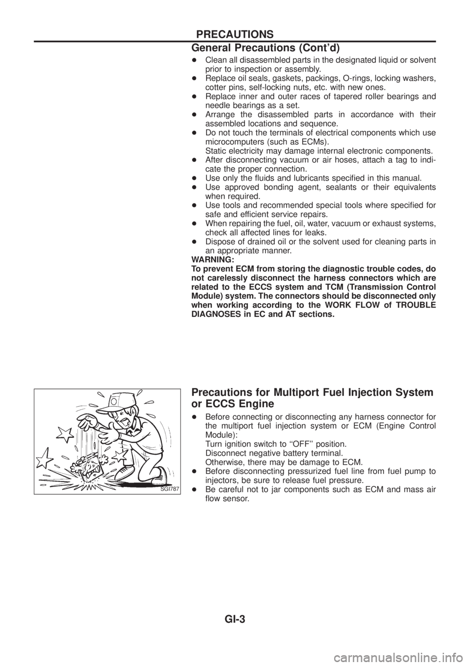
+Before connecting or disconnecting any harness connector for
the multiport fuel injection system or ECM (Engine Control
Module):
Turn ignition switch to ``OFF'' position.
Disconnect negative battery terminal.
Otherwise, there may be damage to ECM.
+
Before disconnecting pressurized fuel line from fuel pump to
injectors, be sure to release fuel pressure.
+Be careful not to jar components such as ECM and mass air
¯ow sensor.SGI787
PRECAUTIONS
General Precautions (Cont'd)
GI-3
Page 787 of 1226
DETECTABLE LINES AND NON-DETECTABLE LINES
In some wiring diagrams, two kinds of lines, representing wires,
with different weight are used.
+A line with regular weight (wider line) represents a ``detectable
line for DTC (Diagnostic Trouble Code)''. A ``detectable line for
DTC'' is a circuit in which ECM (Engine Control Module) can
detect its malfunctions with the on board diagnostic system.
+A line with less weight (thinner line) represents a ``non-detect-
able line for DTC''. A ``non-detectable line for DTC'' is a circuit
in which ECM cannot detect its malfunctions with the on board
diagnostic system.
SGI862-A
HOW TO READ WIRING DIAGRAMS
Description (Cont'd)
GI-14