2006 NISSAN PATROL differential
[x] Cancel search: differentialPage 986 of 1226
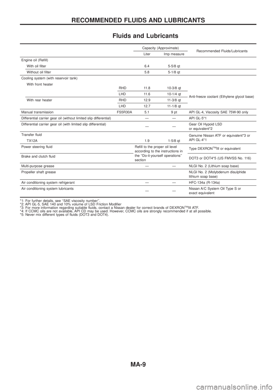
Fluids and Lubricants
Capacity (Approximate)Recommended Fluids/Lubricants
Liter Imp measure
Engine oil (Re®ll) With oil ®lter 6.4 5-5/8 qt
Without oil ®lter 5.8 5-1/8 qt
Cooling system (with reservoir tank)
Anti-freeze coolant (Ethylene glycol base)
With front heater
RHD 11.8 10-3/8 qt
LHD 11.6 10-1/4 qt
With rear heater RHD 12.9 11-3/8 qt LHD 12.7 11-1/8 qt
Manual transmission FS5R30A 5.1 9 pt API GL-4, Viscosity SAE 75W-90 only
Differential carrier gear oil (without limited slip differential) Ð Ð API GL-5*1
Differential carrier gear oil (with limited slip differential) ÐÐGearOilHypoidLSD
orequivalent*2
Transfer ¯uid Genuine Nissan ATF or equivalent*3 or
API GL-4*1
TX12A 1.9 1-5/8 qt
Power steering ¯uid Re®ll to the proper oil level according to the instructions in
the ``Do-it-yourself operations''
sectionType DEXRON
TMIII or equivalent
Brake and clutch ¯uid DOT3 or DOT4*5 (US FMVSS No. 116)
Multi-purpose grease Ð Ð NLGI No. 2 (Lithium soap base)
Propeller shaft grease NLGI No. 2 (Molybdenum disulphide
lithium soap base)
Air conditioning system refrigerant Ð Ð HFC-134a (R-134a)
Air conditioning system lubricants ÐÐNissan A/C System Oil Type S or
exact equivalent
*1: For further details, see ``SAE viscosity number''.
*2:APIGL-5,SAE140and10%volumeofLSDFrictionModi®er
*3: For more information regarding suitable ¯uids, contact a Nissan dealer for correct brands of DEXRON
TMIII ATF.
*4: If CCMC oils are not available, API CD may be used. However, CCMC oils are strongly recommended if at all possible.
*5: Never mix different types of ¯uids (DOT3 and DOT4).
RECOMMENDED FLUIDS AND LUBRICANTS
MA-9
Page 999 of 1226
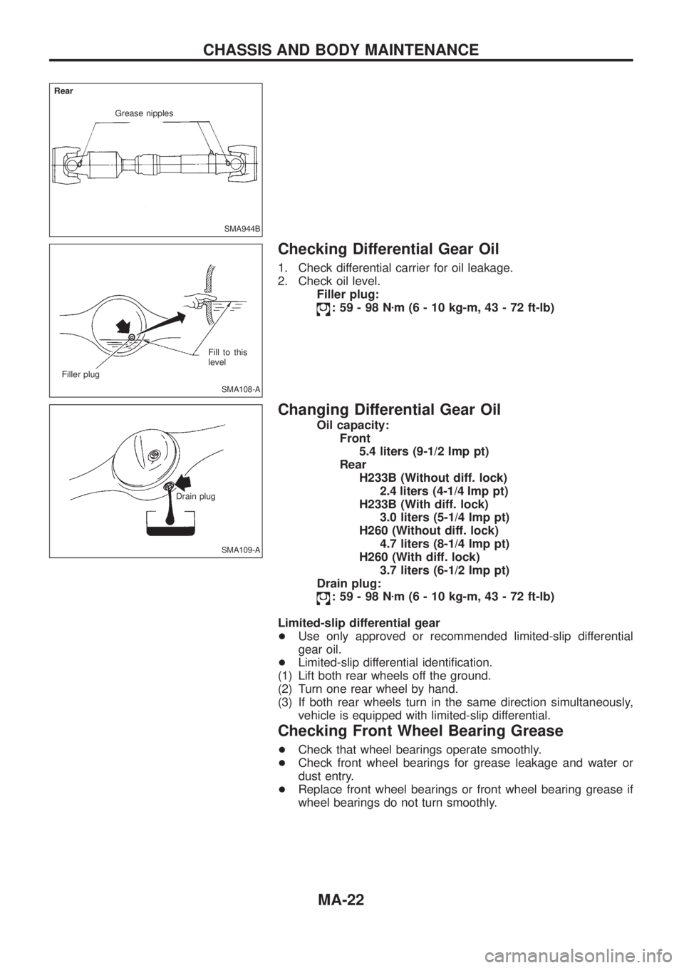
Checking Differential Gear Oil
1. Check differential carrier for oil leakage.
2. Check oil level.Filler plug:
:59-98N zm (6 - 10 kg-m, 43 - 72 ft-lb)
Changing Differential Gear Oil
Oil capacity:
Front5.4 liters (9-1/2 Imp pt)
Rear H233B (Without diff. lock) 2.4 liters(4-1/4 Imppt)
H233B (With diff. lock) 3.0 liters (5-1/4 Imp pt)
H260 (Without diff. lock) 4.7 liters (8-1/4 Imp pt)
H260 (With diff. lock) 3.7 liters (6-1/2 Imp pt)
Drain plug:
:59-98N zm (6 - 10 kg-m, 43 - 72 ft-lb)
Limited-slip differential gear
+ Use only approved or recommended limited-slip differential
gear oil.
+ Limited-slip differential identi®cation.
(1) Lift both rear wheels off the ground.
(2) Turn one rear wheel by hand.
(3) If both rear wheels turn in the same direction simultaneously, vehicle is equipped with limited-slip differential.
Checking Front Wheel Bearing Grease
+Check that wheel bearings operate smoothly.
+ Check front wheel bearings for grease leakage and water or
dust entry.
+ Replace front wheel bearings or front wheel bearing grease if
wheel bearings do not turn smoothly.
SMA944B
Grease nipples
Rear
SMA108-A
Filler plug
Fill to this
level
SMA109-A
Drain plug
CHASSIS AND BODY MAINTENANCE
MA-22
Page 1000 of 1226
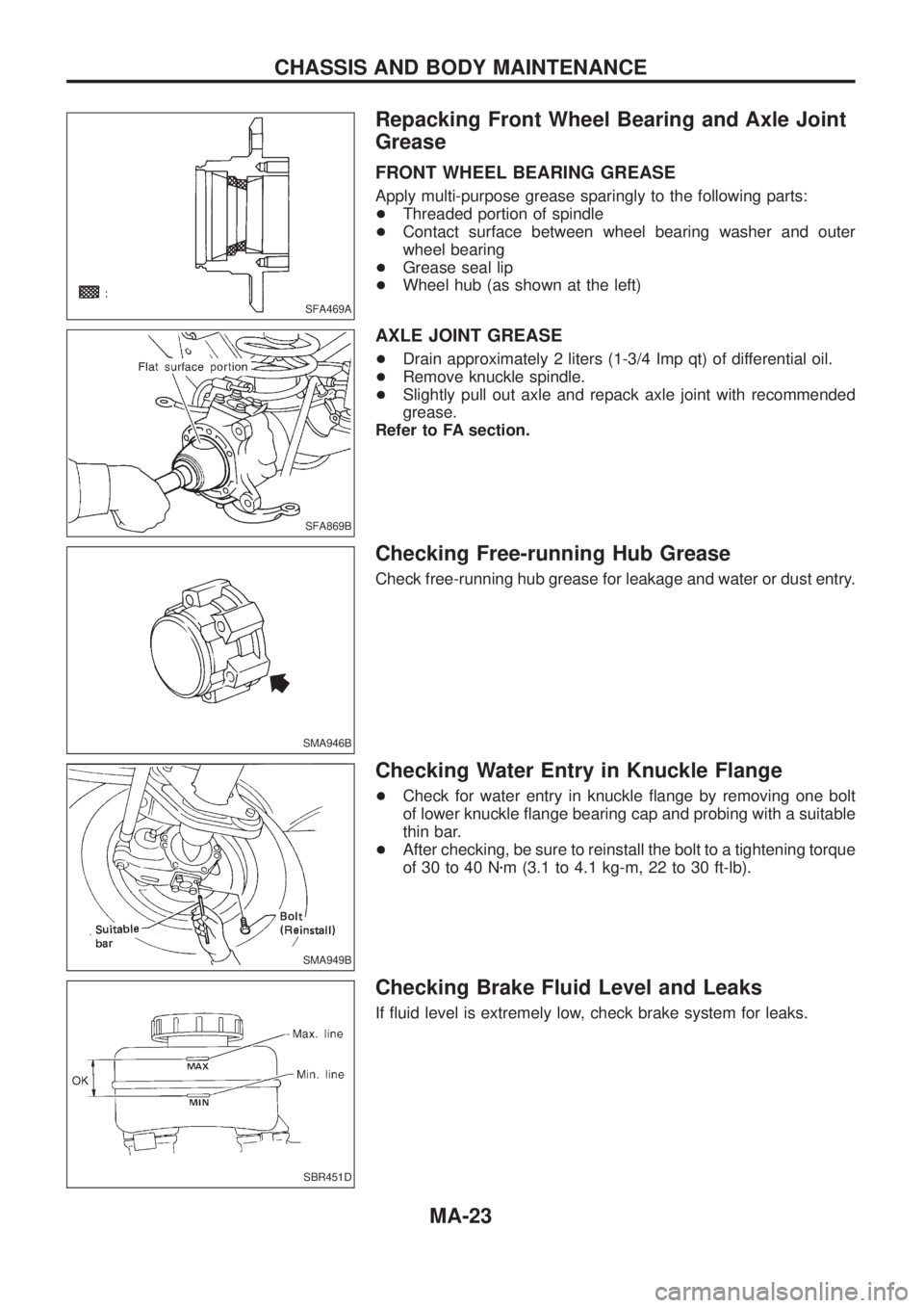
Repacking Front Wheel Bearing and Axle Joint
Grease
FRONT WHEEL BEARING GREASE
Apply multi-purpose grease sparingly to the following parts:
+Threaded portion of spindle
+Contact surface between wheel bearing washer and outer
wheel bearing
+Grease seal lip
+Wheel hub (as shown at the left)
AXLE JOINT GREASE
+Drain approximately 2 liters (1-3/4 Imp qt) of differential oil.
+Remove knuckle spindle.
+Slightly pull out axle and repack axle joint with recommended
grease.
Refer to FA section.
Checking Free-running Hub Grease
Check free-running hub grease for leakage and water or dust entry.
Checking Water Entry in Knuckle Flange
+Check for water entry in knuckle ¯ange by removing one bolt
of lower knuckle ¯ange bearing cap and probing with a suitable
thin bar.
+After checking, be sure to reinstall the bolt to a tightening torque
of 30 to 40 Nzm (3.1 to 4.1 kg-m, 22 to 30 ft-lb).
Checking Brake Fluid Level and Leaks
If ¯uid level is extremely low, check brake system for leaks.
SFA469A
SFA869B
SMA946B
SMA949B
SBR451D
CHASSIS AND BODY MAINTENANCE
MA-23
Page 1042 of 1226
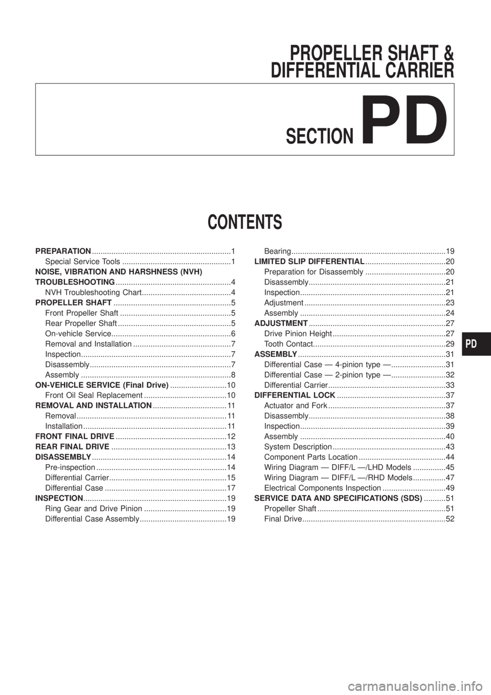
PROPELLER SHAFT &
DIFFERENTIAL CARRIER
SECTION
PD
CONTENTS
PREPARATION................................................................1
Special Service Tools ..................................................1
NOISE, VIBRATION AND HARSHNESS (NVH)
TROUBLESHOOTING.....................................................4
NVH Troubleshooting Chart.........................................4
PROPELLER SHAFT......................................................5
Front Propeller Shaft ...................................................5
Rear Propeller Shaft ....................................................5
On-vehicle Service.......................................................6
Removal and Installation .............................................7
Inspection.....................................................................7
Disassembly.................................................................7
Assembly .....................................................................8
ON-VEHICLE SERVICE (Final Drive)..........................10
Front Oil Seal Replacement ......................................10
REMOVAL AND INSTALLATION.................................. 11
Removal ..................................................................... 11
Installation .................................................................. 11
FRONT FINAL DRIVE...................................................12
REAR FINAL DRIVE.....................................................13
DISASSEMBLY..............................................................14
Pre-inspection ............................................................14
Differential Carrier......................................................15
Differential Case ........................................................17
INSPECTION..................................................................19
Ring Gear and Drive Pinion ......................................19
Differential Case Assembly........................................19Bearing.......................................................................19
LIMITED SLIP DIFFERENTIAL.....................................20
Preparation for Disassembly .....................................20
Disassembly...............................................................21
Inspection...................................................................21
Adjustment .................................................................23
Assembly ...................................................................24
ADJUSTMENT...............................................................27
Drive Pinion Height ....................................................27
Tooth Contact.............................................................29
ASSEMBLY....................................................................31
Differential Case Ð 4-pinion type Ð.........................31
Differential Case Ð 2-pinion type Ð.........................32
Differential Carrier......................................................33
DIFFERENTIAL LOCK..................................................37
Actuator and Fork ......................................................37
Disassembly...............................................................38
Inspection...................................................................39
Assembly ...................................................................40
System Description ....................................................43
Component Parts Location ........................................44
Wiring Diagram Ð DIFF/L Ð/LHD Models ...............45
Wiring Diagram Ð DIFF/L Ð/RHD Models ...............47
Electrical Components Inspection .............................49
SERVICE DATA AND SPECIFICATIONS (SDS)..........51
Propeller Shaft ...........................................................51
Final Drive..................................................................52
PD
Page 1043 of 1226
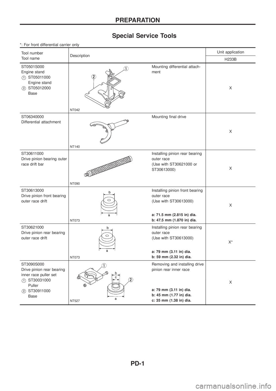
Special Service Tools
*: For front differential carrier only
Tool number
Tool nameDescriptionUnit application
H233B
ST0501S000
Engine stand
V1ST05011000
Engine stand
V2ST05012000
Base
NT042
Mounting differential attach-
ment
X
ST06340000
Differential attachment
NT140
Mounting ®nal drive
X
ST30611000
Drive pinion bearing outer
race drift bar
NT090
Installing pinion rear bearing
outer race
(Use with ST30621000 or
ST30613000)X
ST30613000
Drive pinion front bearing
outer race drift
NT073
Installing pinion front bearing
outer race
(Use with ST30613000)
X
a: 71.5 mm (2.815 in) dia.
b: 47.5 mm (1.870 in) dia.
ST30621000
Drive pinion rear bearing
outer race drift
NT073
Installing pinion rear bearing
outer race
(Use with ST30613000)
X*
a: 79 mm (3.11 in) dia.
b: 59 mm (2.32 in) dia.
ST3090S000
Drive pinion rear bearing
inner race puller set
V1ST30031000
Puller
V2ST30911000
Base
NT527
Removing and installing drive
pinion rear inner race
X
a: 79 mm (3.11 in) dia.
b: 45 mm (1.77 in) dia.
c: 35 mm (1.38 in) dia.
PREPARATION
PD-1
Page 1044 of 1226
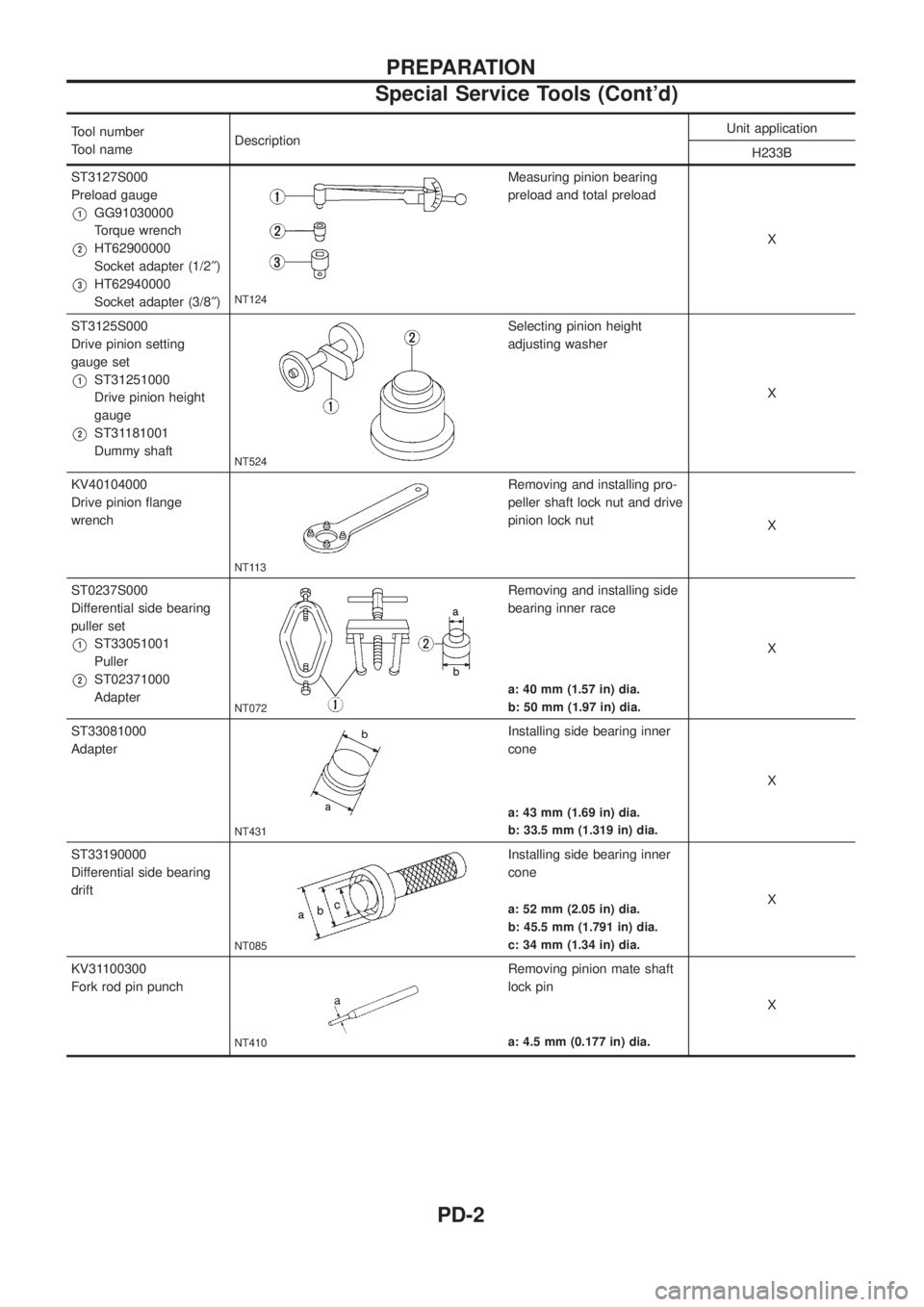
Tool number
Tool nameDescriptionUnit application
H233B
ST3127S000
Preload gauge
V1GG91030000
Torque wrench
V2HT62900000
Socket adapter (1/2²)
V3HT62940000
Socket adapter (3/8²)NT124
Measuring pinion bearing
preload and total preload
X
ST3125S000
Drive pinion setting
gauge set
V1ST31251000
Drive pinion height
gauge
V2ST31181001
Dummy shaft
NT524
Selecting pinion height
adjusting washer
X
KV40104000
Drive pinion ¯ange
wrench
NT113
Removing and installing pro-
peller shaft lock nut and drive
pinion lock nut
X
ST0237S000
Differential side bearing
puller set
V1ST33051001
Puller
V2ST02371000
Adapter
NT072
Removing and installing side
bearing inner race
X
a: 40 mm (1.57 in) dia.
b: 50 mm (1.97 in) dia.
ST33081000
Adapter
NT431
Installing side bearing inner
cone
X
a: 43 mm (1.69 in) dia.
b: 33.5 mm (1.319 in) dia.
ST33190000
Differential side bearing
drift
NT085
Installing side bearing inner
cone
X
a: 52 mm (2.05 in) dia.
b: 45.5 mm (1.791 in) dia.
c: 34 mm (1.34 in) dia.
KV31100300
Fork rod pin punch
NT410
Removing pinion mate shaft
lock pin
X
a: 4.5 mm (0.177 in) dia.
PREPARATION
Special Service Tools (Cont'd)
PD-2
Page 1045 of 1226
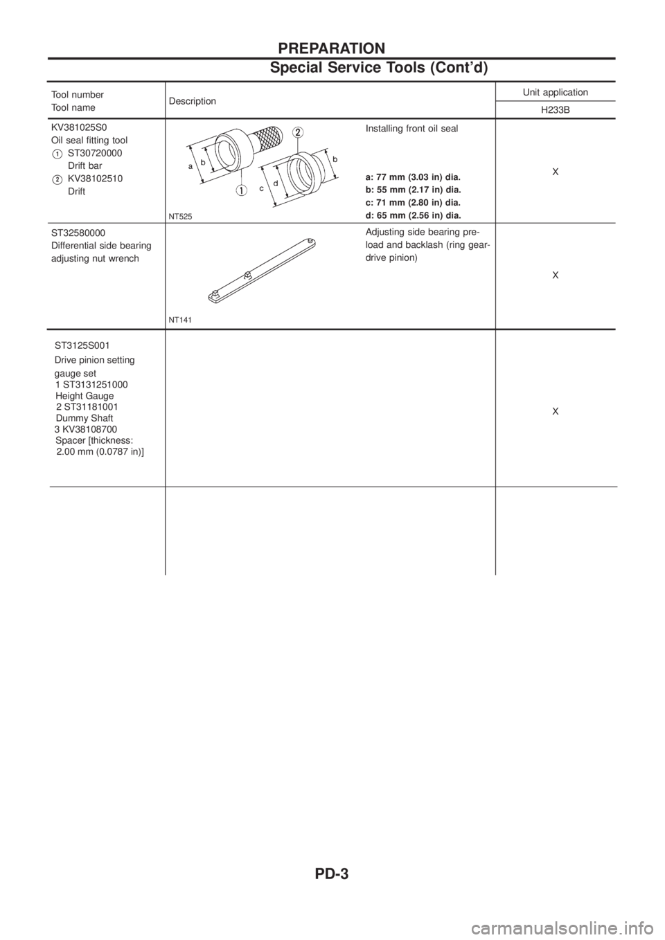
Tool number
Tool nameDescription Unit application
H233B
KV381025S0
Oil seal ®tting tool
V1ST30720000
Drift bar
V2KV38102510
Drift
NT525
Installing front oil seal
X
a: 77 mm (3.03 in) dia.
b: 55 mm (2.17 in) dia.
c: 71 mm (2.80 in) dia.
d: 65 mm (2.56 in) dia.
ST32580000
Differentialsidebearing
adjustingnutwrench
ST3125S001 Drive pinion setting gauge set 1 ST3131251000 Height Gauge 2 ST31181001
Dummy Shaft
3 KV38108700 Spacer [thickness: 2.00 mm (0.0787 in)]
NT141
Adjusting side bearing pre-
load and backlash (ring gear-
drive pinion)
X
X
PREPARATION
Special Service Tools (Cont'd)
PD-3
Page 1046 of 1226
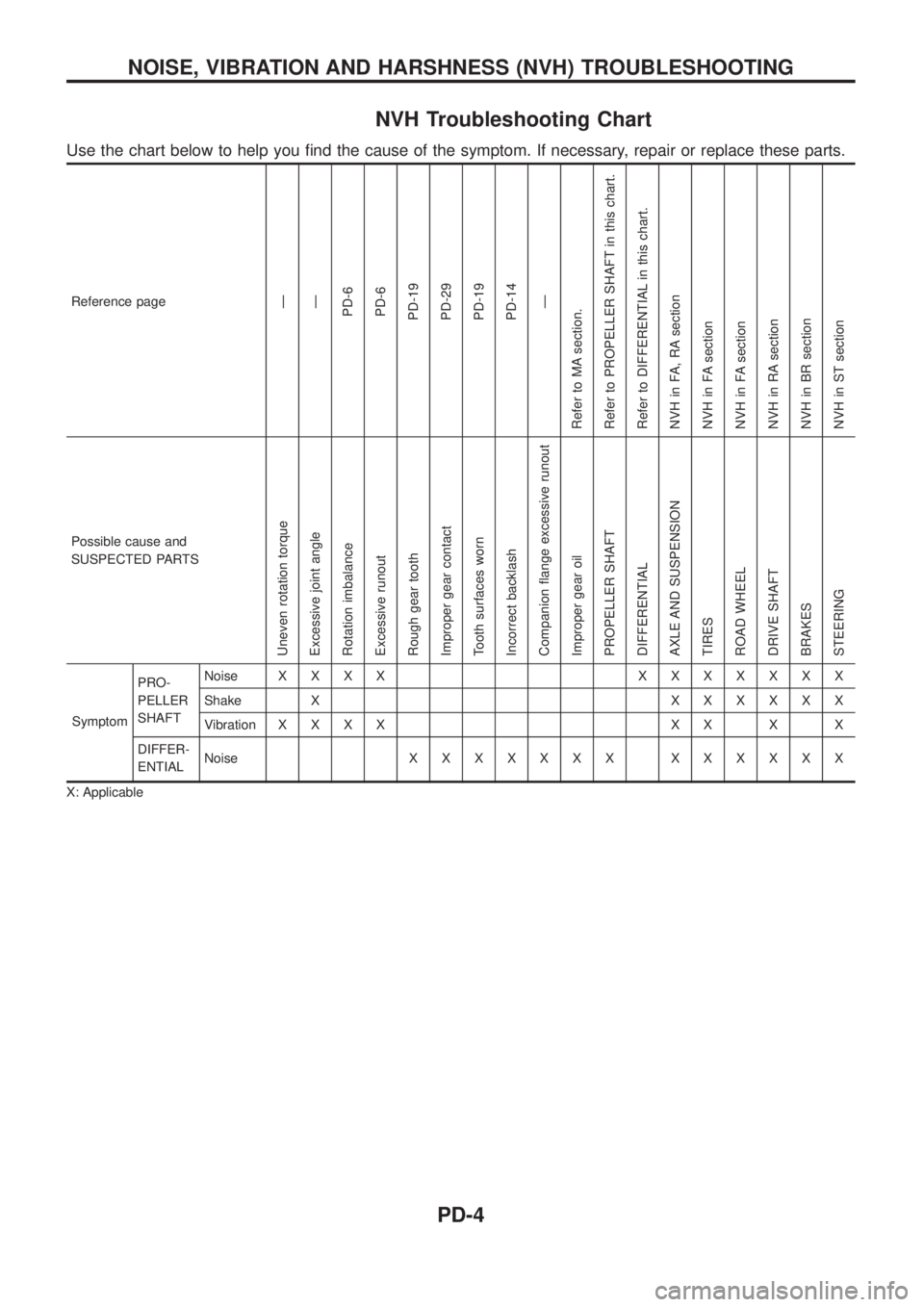
NVH Troubleshooting Chart
Use the chart below to help you ®nd the cause of the symptom. If necessary, repair or replace these parts.
Reference pageÐ
Ð
PD-6
PD-6
PD-19
PD-29
PD-19
PD-14
Ð
Refer to MA section.
Refer to PROPELLER SHAFT in this chart.
Refer to DIFFERENTIAL in this chart.
NVH in FA, RA section
NVH in FA section
NVH in FA section
NVH in RA section
NVH in BR section
NVH in ST section
Possible cause and
SUSPECTED PARTS
Uneven rotation torque
Excessive joint angle
Rotation imbalance
Excessive runout
Rough gear tooth
Improper gear contact
Tooth surfaces worn
Incorrect backlash
Companion ¯ange excessive runout
Improper gear oil
PROPELLER SHAFT
DIFFERENTIAL
AXLE AND SUSPENSION
TIRES
ROAD WHEEL
DRIVE SHAFT
BRAKES
STEERING
SymptomPRO-
PELLER
SHAFTNoiseXXXX XXXXXXX
Shake XXXXXXX
VibrationXXXX XX X X
DIFFER-
ENTIALNoiseXXXXXXX XXXXXX
X: Applicable
NOISE, VIBRATION AND HARSHNESS (NVH) TROUBLESHOOTING
PD-4