2006 NISSAN PATROL clock
[x] Cancel search: clockPage 944 of 1226

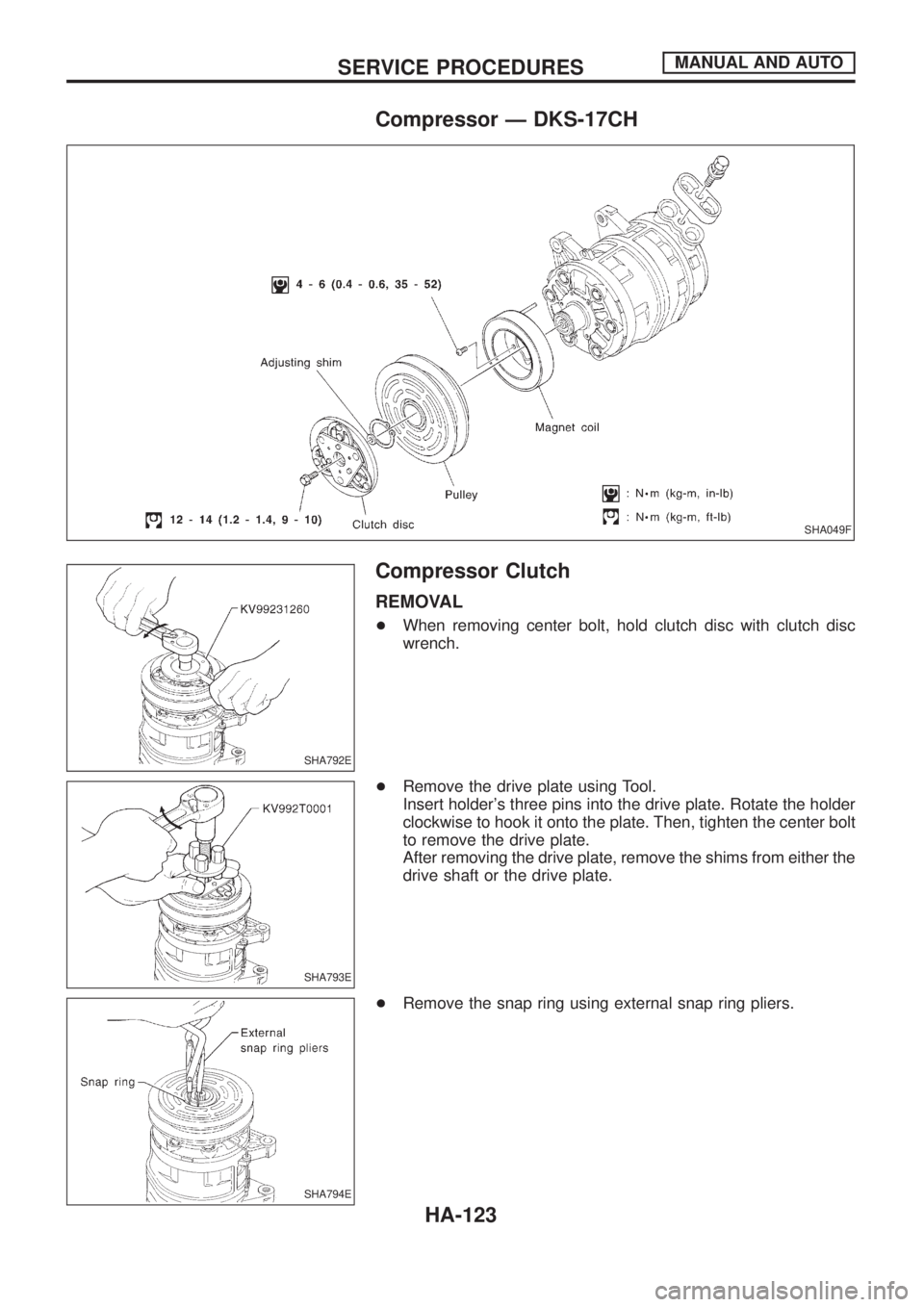
Compressor Ð DKS-17CH
Compressor Clutch
REMOVAL
+When removing center bolt, hold clutch disc with clutch disc
wrench.
+Remove the drive plate using Tool.
Insert holder's three pins into the drive plate. Rotate the holder
clockwise to hook it onto the plate. Then, tighten the center bolt
to remove the drive plate.
After removing the drive plate, remove the shims from either the
drive shaft or the drive plate.
+Remove the snap ring using external snap ring pliers.
SHA049F
SHA792E
SHA793E
SHA794E
SERVICE PROCEDURESMANUAL AND AUTO
HA-123
Page 947 of 1226

General Speci®cations
COMPRESSOR
Model ZEXEL make DKS-17CH
Type Swash plate
Displacement cm
3(cu in)/rev. 168 (10.25)
Cylinder bore x stroke mm (in) 37.0 x 25.8 (1.457 x 1.016)
Direction of rotationClockwise
(Viewed from drive end)
Drive belt A Type
LUBRICANT
Model ZEXEL make DKS-17CH
Type KLH00-PAGS0
Capacity m!(lmp ¯ oz)
Total in system 300 (10.6)
Compressor (Service parts)
charging amount300 (10.6)
Inspection and Adjustment
REFRIGERANT
Front A/C
Type HFC-134a (R-134a)
Capacity kg (lb)0.75 - 0.85
(1.65 - 1.87)
ENGINE IDLING SPEED (When A/C is ON.)
+Refer to EC section.
BELT TENSION
+Refer to MA section (``Checking Drive Belts'',
``ENGINE MAINTENANCE'').
COMPRESSOR
Model DKS-17CH
Clutch disc-to-pulley clearance
mm (in)0.3 - 0.6
(0.012 - 0.024)
SERVICE DATA AND SPECIFICATIONS
(SDS)MANUAL AND AUTO
HA-126
Page 949 of 1226

A
A/C HFC134a (R134a) system service
procedure ..................................................HA-112
A/C HFC134a system service equip-
ment precaution ............................................HA-9
A/C air ¯ow .....................................................HA-13
A/C component layout ....................................HA-12
A/C compressor precaution..............................HA-6
A/C compressor special service tool ...........HA-6, 7
A/C control linkage adjustment (auto
A/C).............................................................HA-77
A/C control operation (manual A/C) ...............HA-16
A/C harness layout (manual A/C) ..................HA-17
A/C lubricant (R134a) ...................................HA-114
A/C relay.........................................................HA-97
A/C self-diagnoses (auto A/C)........................HA-63
A/CCUT - Wiring diagram ............................EC-186
A/T control ....................................................EC-174
ABS sensor rotor ............................................FA-15
ACC/SW - Wiring diagram ...........................EC-105
ACL/SW - Wiring diagram ............................EC-164
ADJRES - Wiring diagram .............................EC-91
APS - Wiring diagram ..................................EC-138
AT/C - Wiring diagram..................................EC-174
AUDIO - Wiring diagram ...............................EL-168
Accelerator position sensor ..........................EC-138
Accelerator position switch...........................EC-164
Accelerator switch (F/C) ...............................EC-105
Adjustment resistor.........................................EC-91
Air bag disposal..............................................RS-17
Air bag ..............................................................RS-8
Air bleeding (hydraulic clutch) ..........................CL-6
Air bleeding for brake system ..........................BR-4
Air cleaner ®lter replacement .........................MA-18
Air conditioner cut control ..............................EC-19
Air ¯ow meter - See Mass air ¯ow
sensor .........................................................EC-73
Air mix door control linkage
adjustment ................................................HA-81
Alternator.........................................................EL-56
Antenna - See Power antenna .....................EL-181
Audio and A/C control removal and
installation - See Instrument panel .............BT-11
Audio .............................................................EL-168
Auto lock free running hub .............................FA-13
Automatic ampli®er .........................................HA-61
Axle housing (rear) ...........................................RA-9
B
BACK/L - Wiring diagram................................EL-78
Back door opener - See Back door ..................BT-6
Back door trim.................................................BT-24
Back door window...........................................BT-45
Back door ..........................................................BT-6Back-up lamp switch (M/T) ..............................MT-4
Back-up lamp ..................................................EL-78
Battery .............................................................EL-37
Baulk ring (M/T)..............................................MT-10
Body alignment ...............................................BT-49
Body mounting ................................................BT-48
Brake booster .................................................BR-15
Brake ¯uid change ...........................................BR-3
Brake ¯uid level and line check .......................BR-3
Brake ¯uid level .............................................MA-23
Brake hydraulic line ..........................................BR-5
Brake inspection ............................................MA-24
Brake master cylinder ....................................BR-12
Brake pedal ....................................................BR-10
Bulb speci®cations ........................................EL-314
Bumper, front ................................................... BT-4
Bumper, rear .....................................................BT-6
C
CD/CHG - Wiring diagram ............................EL-176
CHIME - Wiring diagram...............................EL-136
CIGAR - Wiring diagram ...............................EL-156
CKPS - Wiring diagram ................................EC-143
CLOCK - Wiring diagram ..............................EL-157
CMPS - Wiring diagram .................................EC-68
COMPAS - Wiring diagram ...........................EL-117
CONSULT for ECCS ......................................EC-36
CONSULT general information ........................GI-33
COOL/F - Wiring diagram ............................EC-112
CSPS - Wiring diagram ..................................EC-86
Cab body.........................................................BT-47
Camshaft inspection ......................................EM-36
Camshaft position sensor (PUMP).................EC-68
Center case (Transfer) ....................................TF-10
Charge air cooler fan control .......................EC-177
Charge air temperature sensor ....................EC-121
Chassis and body maintenance ....................MA-20
Cigarette lighter.............................................EL-156
Circuit breaker.................................................EL-14
Clock .............................................................EL-157
Clutch booster...................................................CL-9
Clutch cover ....................................................CL-14
Clutch damper ..................................................CL-7
Clutch disc ......................................................CL-13
Clutch ¯uid level.............................................MA-20
Clutch master cylinder ......................................CL-7
Clutch operating cylinder ..................................CL-8
Clutch pedal ......................................................CL-5
Clutch release bearing ....................................CL-11
Clutch release mechanism .............................CL-11
Clutch withdrawal lever ...................................CL-11
Coil spring (front) ............................................FA-25
Coil spring (rear) ............................................RA-14
Collision diagnosis..........................................RS-45
Combination meter removal and instal-
lation - See Instrument panel ......................BT-11
ALPHABETICAL INDEX
IDX-2
Page 979 of 1226

Shown below are Pre-delivery Inspection Items required for the new vehicle. It is recommended that
necessary items other than those listed here be added, paying due regard to the conditions in each
country.
Perform applicable items on each model. Consult text of this section for speci®cations.
UNDER HOOD Ð engine off
hRadiator coolant level and coolant hose connec-
tions for leaks
hBattery ¯uid level, speci®c gravity and condi-
tions of battery terminals
hDrive belts tension
hFuel ®lter for water or dusts, and fuel lines and
connections for leaks
hEngine oil level and oil leaks
hClutch and brake reservoir ¯uid level and ¯uid
lines for leaks
hWindshield and rear window washer and head-
lamp cleaner reservoir ¯uid level
hPower steering reservoir ¯uid level and hose
connections for leaks
ON INSIDE AND OUTSIDE
hXRemove front spring/strut spacer (If applicable)
hOperation of all instruments, gauges, lights and
accessories
hOperation of horn(s), wiper and washer
hSteering lock for operation
hCheck air conditioner for gas leaks
hFront and rear seats, and seat belts for opera-
tion
hAll moldings, trims and ®ttings for ®t and align-
ment
hAll windows for operation and alignment
hHood, trunk lid, door panels for ®t and alignment
hLatches, keys and locks for operation
hWeatherstrips for adhesion and ®t
hHeadlamp aiming
hTighten wheel nuts (Inc. inner nuts if applicable)
hTire pressure (Inc. spare tire)
hCheck front wheels for toe-in
hInstall clock/voltmeter/room lamp fuse (If appli-
cable)
h
XInstall deodorizing ®lter to air puri®er (If appli-
cable)
h
XRemove wiper blade protectors (If applicable)
UNDER BODY
hManual transmission/transaxle gear oil, transfer
¯uid and differential gear oil level
hBrake and fuel lines and oil/¯uid reservoirs for
leaks
hTighten bolts and nuts of steering linkage and
gear box, suspension, propeller shafts and drive
shafts
h
XTighten rear body bolts and nuts (Models with
wooden bed only)
ROAD TEST
hClutch operation
hParking brake operation
hService brake operation
hAutomatic transmission/transaxle shift timing
and kickdown
hSteering control and returnability
hEngine performance
hSqueaks and rattles
ENGINE OPERATING AND HOT
hAdjust idle mixture and speed (and ignition tim-
ing*1)
hAutomatic transmission/transaxle ¯uid level
hEngine idling and stop knob operation (Diesel
only)
FINAL INSPECTION
hInstall necessary parts (outside mirror, wheel
covers, seat belts, mat, carpet or mud ¯aps)
hInspect for interior and exterior metal and paint
damage
hCheck for spare tire, jack, tools (wheel chock),
and literature
hWash, clean interior and exterior
*1: Not required on models with a direct ignition system
h
X: Not applicable to this model.
PRE-DELIVERY INSPECTION ITEMS
MA-2