2006 NISSAN PATROL charging
[x] Cancel search: chargingPage 831 of 1226
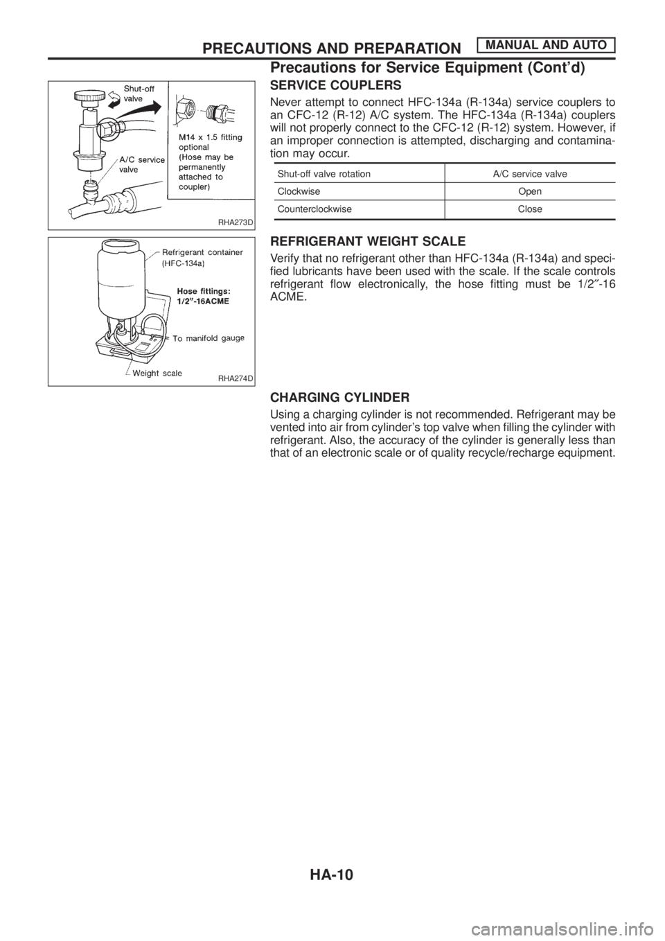
SERVICE COUPLERS
Never attempt to connect HFC-134a (R-134a) service couplers to
an CFC-12 (R-12) A/C system. The HFC-134a (R-134a) couplers
will not properly connect to the CFC-12 (R-12) system. However, if
an improper connection is attempted, discharging and contamina-
tion may occur.
Shut-off valve rotation A/C service valve
Clockwise Open
Counterclockwise Close
REFRIGERANT WEIGHT SCALE
Verify that no refrigerant other than HFC-134a (R-134a) and speci-
®ed lubricants have been used with the scale. If the scale controls
refrigerant ¯ow electronically, the hose ®tting must be 1/2²-16
ACME.
CHARGING CYLINDER
Using a charging cylinder is not recommended. Refrigerant may be
vented into air from cylinder's top valve when ®lling the cylinder with
refrigerant. Also, the accuracy of the cylinder is generally less than
that of an electronic scale or of quality recycle/recharge equipment.
RHA273D
RHA274D
PRECAUTIONS AND PREPARATIONMANUAL AND AUTO
Precautions for Service Equipment (Cont'd)
HA-10
Page 933 of 1226
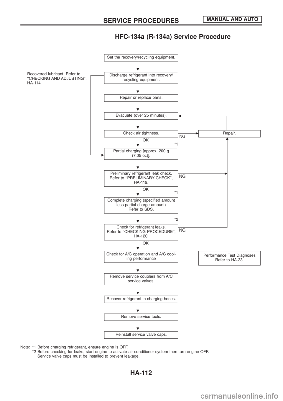
HFC-134a (R-134a) Service Procedure
Set the recovery/recycling equipment.
Recovered lubricant. Refer to
``CHECKING AND ADJUSTING'',
HA-114.
c
Discharge refrigerant into recovery/
recycling equipment.
Repair or replace parts.
Evacuate (over 25 minutes).b
Check air tightness.
OK
*1
cNGRepair.m
Partial charging [approx. 200 g
(7.05 oz)].
Preliminary refrigerant leak check.
Refer to ``PRELIMINARY CHECK'',
HA-119.
OK
*1
cNG
Complete charging (speci®ed amount
less partial charge amount)
Refer to SDS.
*2
Check for refrigerant leaks.
Refer to ``CHECKING PROCEDURE'',
HA-120.
OK
NG
Check for A/C operation and A/C cool-
ing performance..................
Performance Test Diagnoses
Refer to HA-33.
Remove service couplers from A/C
service valves.
Recover refrigerant in charging hoses.
Remove service tools.
Reinstall service valve caps.
Note: *1 Before charging refrigerant, ensure engine is OFF.
*2 Before checking for leaks, start engine to activate air conditioner system then turn engine OFF.
Service valve caps must be installed to prevent leakage.
.
.
.
.
.
.
.
.
.
.
.
.
.
SERVICE PROCEDURESMANUAL AND AUTO
HA-112
Page 934 of 1226
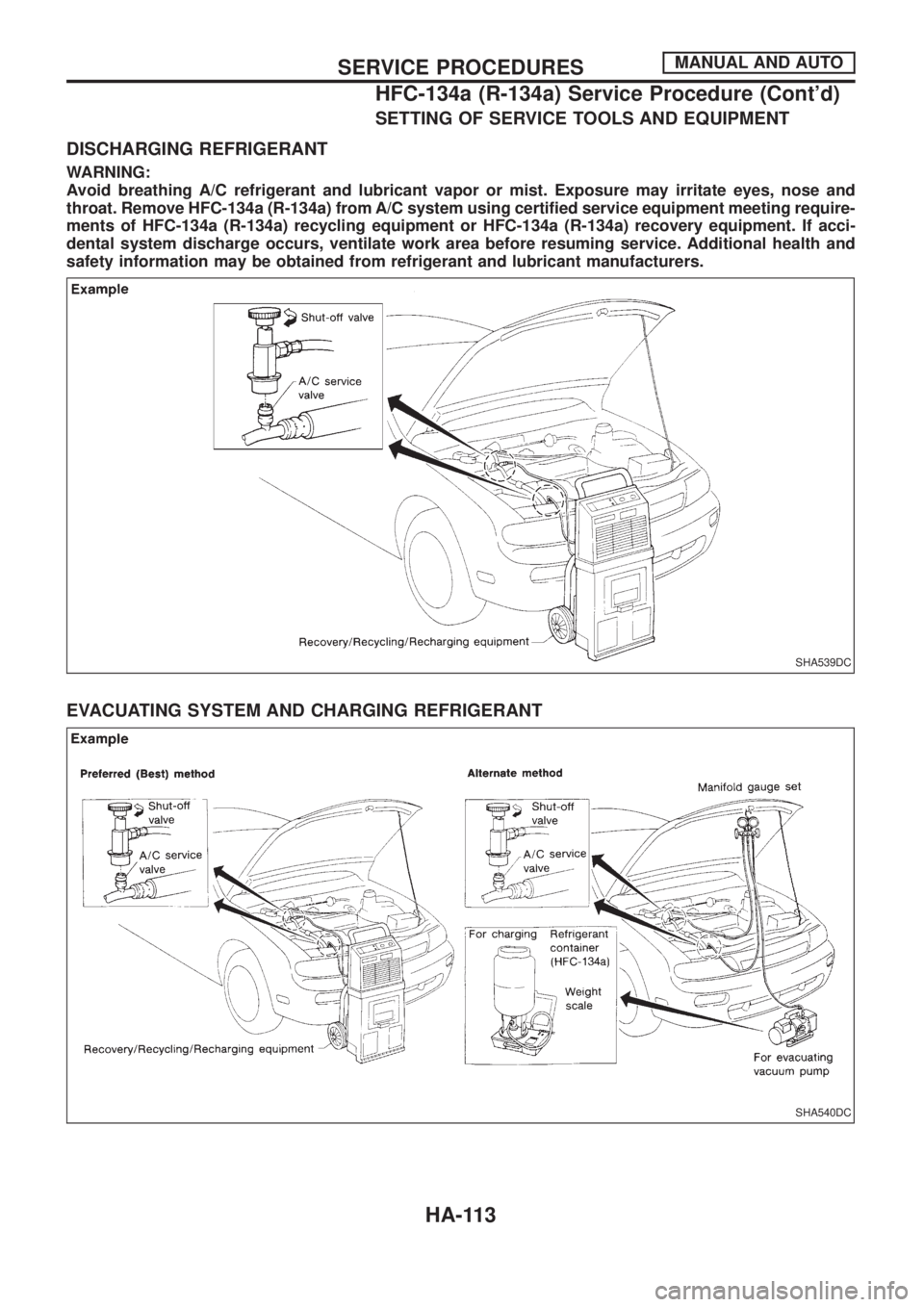
SETTING OF SERVICE TOOLS AND EQUIPMENT
DISCHARGING REFRIGERANT
WARNING:
Avoid breathing A/C refrigerant and lubricant vapor or mist. Exposure may irritate eyes, nose and
throat. Remove HFC-134a (R-134a) from A/C system using certi®ed service equipment meeting require-
ments of HFC-134a (R-134a) recycling equipment or HFC-134a (R-134a) recovery equipment. If acci-
dental system discharge occurs, ventilate work area before resuming service. Additional health and
safety information may be obtained from refrigerant and lubricant manufacturers.
EVACUATING SYSTEM AND CHARGING REFRIGERANT
SHA539DC
SHA540DC
SERVICE PROCEDURESMANUAL AND AUTO
HFC-134a (R-134a) Service Procedure (Cont'd)
HA-113
Page 936 of 1226
jA
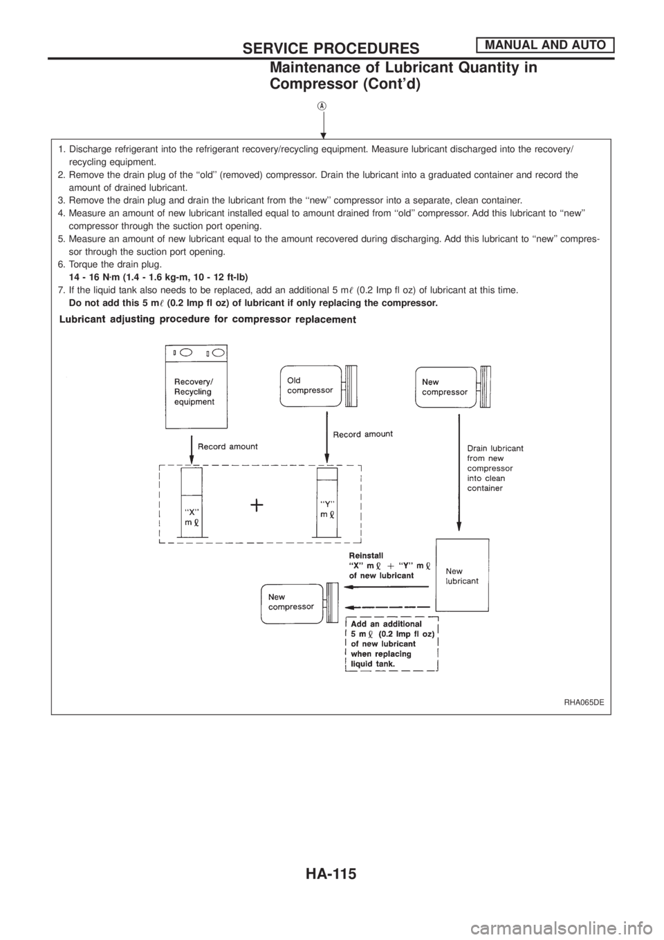
1. Discharge refrigerant into the refrigerant recovery/recycling equipment. Measure lubricant discharged into the recovery/
recycling equipment.
2. Remove the drain plug of the ``old'' (removed) compressor. Drain the lubricant into a graduated container and record the
amount of drained lubricant.
3. Remove the drain plug and drain the lubricant from the ``new'' compressor into a separate, clean container.
4. Measure an amount of new lubricant installed equal to amount drained from ``old'' compressor. Add this lubricant to ``new''
compressor through the suction port opening.
5. Measure an amount of new lubricant equal to the amount recovered during discharging. Add this lubricant to ``new'' compres-
sor through the suction port opening.
6. Torque the drain plug.
14-16Nzm (1.4 - 1.6 kg-m, 10 - 12 ft-lb)
7. If the liquid tank also needs to be replaced, add an additional 5 m!(0.2 Imp ¯ oz) of lubricant at this time.
Do not add this 5 m!(0.2 Imp ¯ oz) of lubricant if only replacing the compressor.
RHA065DE
.
SERVICE PROCEDURESMANUAL AND AUTO
Maintenance of Lubricant Quantity in
Compressor (Cont'd)
HA-115
Page 947 of 1226
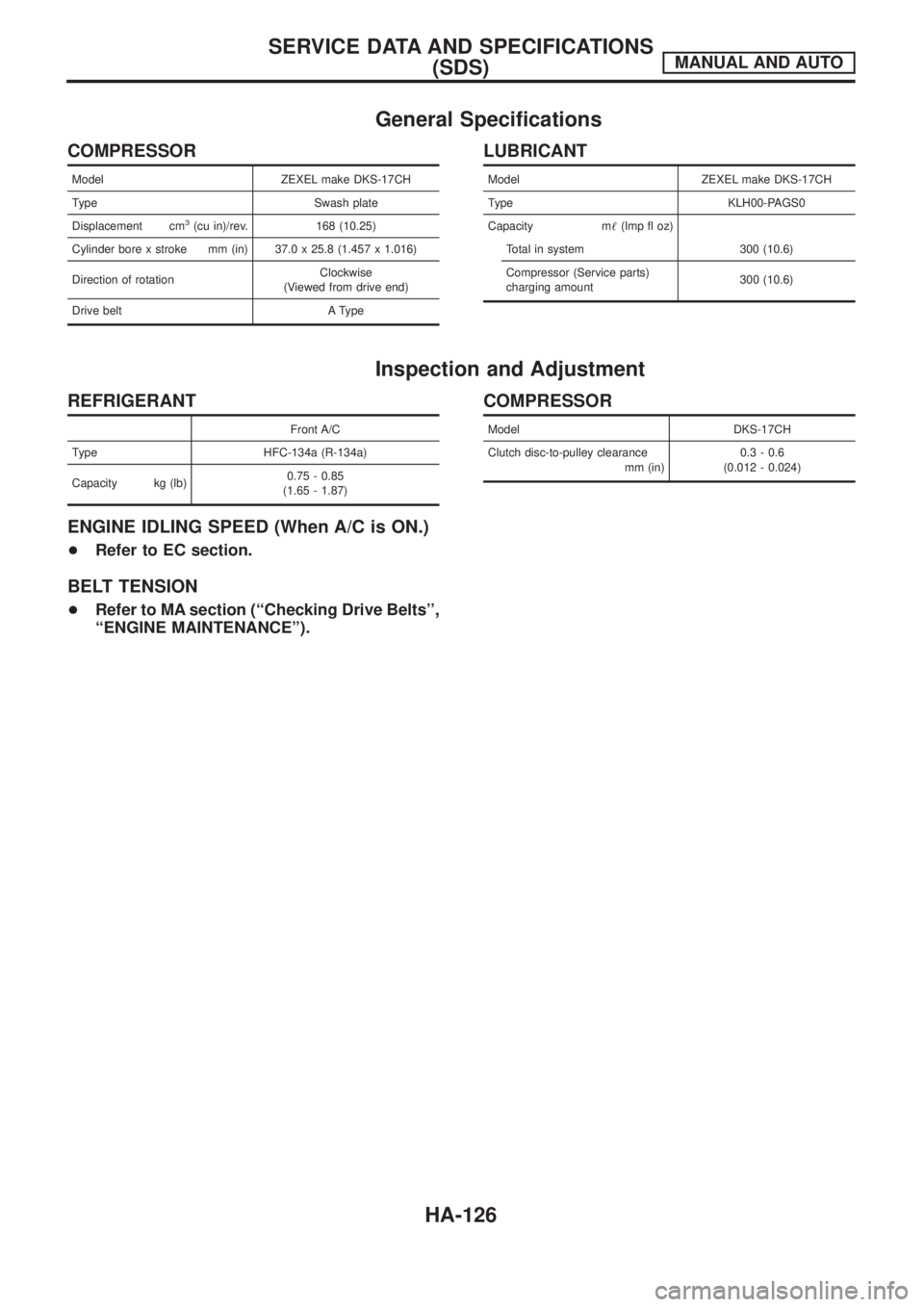
General Speci®cations
COMPRESSOR
Model ZEXEL make DKS-17CH
Type Swash plate
Displacement cm
3(cu in)/rev. 168 (10.25)
Cylinder bore x stroke mm (in) 37.0 x 25.8 (1.457 x 1.016)
Direction of rotationClockwise
(Viewed from drive end)
Drive belt A Type
LUBRICANT
Model ZEXEL make DKS-17CH
Type KLH00-PAGS0
Capacity m!(lmp ¯ oz)
Total in system 300 (10.6)
Compressor (Service parts)
charging amount300 (10.6)
Inspection and Adjustment
REFRIGERANT
Front A/C
Type HFC-134a (R-134a)
Capacity kg (lb)0.75 - 0.85
(1.65 - 1.87)
ENGINE IDLING SPEED (When A/C is ON.)
+Refer to EC section.
BELT TENSION
+Refer to MA section (``Checking Drive Belts'',
``ENGINE MAINTENANCE'').
COMPRESSOR
Model DKS-17CH
Clutch disc-to-pulley clearance
mm (in)0.3 - 0.6
(0.012 - 0.024)
SERVICE DATA AND SPECIFICATIONS
(SDS)MANUAL AND AUTO
HA-126
Page 953 of 1226
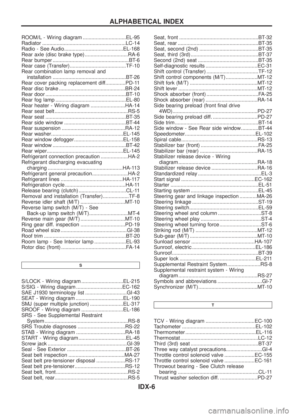
ROOM/L - Wiring diagram ..............................EL-95
Radiator ..........................................................LC-14
Radio - See Audio.........................................EL-168
Rear axle (disc brake type) ..............................RA-6
Rear bumper .....................................................BT-6
Rear case (Transfer) .......................................TF-10
Rear combination lamp removal and
installation ...................................................BT-26
Rear cover packing replacement diff..............PD-11
Rear disc brake ..............................................BR-24
Rear door ........................................................BT-10
Rear fog lamp .................................................EL-80
Rear heater - Wiring diagram ........................HA-14
Rear seat belt ...................................................RS-5
Rear seat ........................................................BT-35
Rear side window ...........................................BT-44
Rear suspension ............................................RA-12
Rear washer..................................................EL-145
Rear window defogger ..................................EL-158
Rear window ...................................................BT-42
Rear wiper.....................................................EL-145
Refrigerant connection precaution ...................HA-2
Refrigerant discharging evacuating
charging ....................................................HA-113
Refrigerant general precaution.........................HA-2
Refrigerant lines ...........................................HA-117
Refrigeration cycle ..........................................HA-11
Release bearing (clutch) .................................CL-11
Removal and installation (Transfer) ..................TF-8
Reverse idler shaft (M/T) ...............................MT-10
Reverse lamp switch (M/T) - See
Back-up lamp switch (M/T)...........................MT-4
Reverse main gear (M/T) ...............................MT-10
Ring gear diff. inspection ...............................PD-19
Road wheel size ..............................................GI-38
Roof trim .........................................................BT-20
Room lamp - See Interior lamp ......................EL-93
Rotor disc (front) .............................................FA-14
S
S/LOCK - Wiring diagram .............................EL-215
S/SIG - Wiring diagram ................................EC-162
SAE J1930 terminology list .............................GI-43
SEAT - Wiring diagram .................................EL-190
SMJ (super multiple junction) .......................EL-317
SROOF - Wiring diagram .............................EL-186
SRS - See Supplemental Restraint
System ..........................................................RS-8
SRS Trouble diagnoses .................................RS-22
STAB - Wiring diagram ..................................RA-18
START - Wiring diagram .................................EL-45
Screw jack .......................................................GI-39
Seal - See Exterior .........................................BT-26
Seat belt inspection .......................................MA-27
Seat belt pre-tensioner disposal ....................RS-17
Seat belt pre-tensioner ...................................RS-12
Seat belt, front ..................................................RS-2
Seat belt, rear...................................................RS-5Seat, front .......................................................BT-32
Seat, rear ........................................................BT-35
Seat, second (2nd) .........................................BT-35
Seat, third (3rd) ...............................................BT-37
Second (2nd) seat ..........................................BT-35
Self-diagnostic results ....................................EC-31
Shift control (Transfer) ....................................TF-12
Shift control components (M/T) ......................MT-12
Shift fork (M/T) ...............................................MT-12
Shift lever .......................................................MT-12
Shock absorber (front) ....................................FA-25
Shock absorber (rear) ....................................RA-14
Side bearing preload (front ®nal drive
4WD)...........................................................PD-27
Side bearing preload diff. ...............................PD-27
Side trim ..........................................................BT-14
Side window - See Rear side window ............BT-44
Speedometer.................................................EL-102
Spiral cable.....................................................RS-13
Stabilizer bar (front) ........................................FA-25
Stabilizer bar (rear) ........................................RA-15
Stabilizer release device - Wiring
diagram .......................................................RA-18
Stabilizer release device ................................RA-16
Standardized relay ............................................EL-3
Start signal ...................................................EC-162
Starter .............................................................EL-51
Starting system ...............................................EL-45
Steering gear and linkage inspection ............MA-26
Steering linkage ..............................................ST-19
Steering switch................................................EL-59
Steering wheel and column ..............................ST-8
Steering wheel play ..........................................ST-4
Steering wheel turning force .............................ST-6
Striking rod (M/T) ...........................................MT-12
Sub-gear (M/T) ...............................................MT-10
Sunload sensor ............................................HA-107
Sunroof, electric ............................................EL-186
Sunroof............................................................BT-39
Super lock .....................................................EL-211
Supplemental Restraint System .......................RS-8
Supplemental restraint system - Wiring
diagram .......................................................RS-27
Symbols and abbreviations ...............................GI-7
Synchronizer (M/T) .........................................MT-10
T
TCV - Wiring diagram ..................................EC-100
Tachometer ...................................................EL-102
Thermometer .................................................EL-116
Thermostat ......................................................LC-12
Third (3rd) seat ...............................................BT-37
Three way catalyst precautions.........................GI-4
Throttle control solenoid valve .....................EC-155
Throttle control solenoid valve .....................EC-161
Throwout bearing - See Clutch release
bearing ........................................................CL-11
Thrust washer selection diff. ..........................PD-27
ALPHABETICAL INDEX
IDX-6
Page 1155 of 1226
![NISSAN PATROL 2006 Service Manual If no self-diagnostic failure is detected on ``SELF-DIAG [CUR-
RENT] even though malfunction is detected in SRS Operation
Check (User mode), check the battery voltage. If the battery volt-
age is le NISSAN PATROL 2006 Service Manual If no self-diagnostic failure is detected on ``SELF-DIAG [CUR-
RENT] even though malfunction is detected in SRS Operation
Check (User mode), check the battery voltage. If the battery volt-
age is le](/manual-img/5/57368/w960_57368-1154.png)
If no self-diagnostic failure is detected on ``SELF-DIAG [CUR-
RENT]'' even though malfunction is detected in SRS Operation
Check (User mode), check the battery voltage. If the battery volt-
age is less than 9V, charge the battery. Then go to DIAGNOSTIC
PROCEDURE 3, page RS-34. If the battery voltage is OK, go to
DIAGNOSTIC PROCEDURE 4, page RS-36, to diagnose the fol-
lowing cases:
+Self-diagnostic failure ``SELF-DIAG [PAST]'' (previously stored
in the memory) might not be erased after repair.
+The SRS system malfunctions intermittently.
8. Touch ``PRINT''.
9. Compare diagnostic codes to ``CONSULT DIAGNOSTIC CODE
CHART'', page RS-33.
10. Touch ``BACK'' key of CONSULT until ``SELECT SYSTEM''
appears in order to return to User mode from Diagnosis mode,
then turn off CONSULT.
11. Turn ignition switch ``OFF'', then disconnect CONSULT and
both battery cables.
12. Repair the system as outlined by the ``Repair order'' in ``CON-
SULT DIAGNOSTIC CODE CHART'', that corresponds to the
problem code. For replacement procedure of component parts,
refer to RS-12.
13. After repairing the system, go to DIAGNOSTIC PROCEDURE
3, page RS-34 for ®nal checking.
CONSULT can only show one seat belt pre-tensioner malfunc-
tion as self-diagnosis result at a time. Check self-diagnosis
result with CONSULT whether other malfunctions are detected
after repairing one seat belt pre-tensioner malfunction.
CONSULT DIAGNOSTIC CODE CHART (``SELF-DIAG
[CURRENT]'')
Diagnostic item ExplanationRepair order
``Recheck SRS at each replacement.''
NO SELF DIAGNOSTIC
FAILURE INDICATED.When malfunction is
indicated by the ``AIR
BAG'' warning lamp in
User mode+Low battery voltage
(Less than 9V)+Go to DIAGNOSTIC PROCEDURE 3 (RS-34)
after charging battery.
+Self-diagnostic fail-
ure ``SELF-DIAG
[PAST]'' (previously
stored in the
memory) might not
be erased after
repair.
+Intermittent problem
has been detected
in the past.+Go to DIAGNOSTIC PROCEDURE 4 (RS-36).
+No malfunction is detected.+Go to DIAGNOSTIC PROCEDURE 3 (RS-34).
AIRBAG MODULE
[OPEN]+Driver's air bag module circuit is open.
(including the spiral cable)1. Visually check the wiring harness connection.
2. Replace the harness if it has visible damage.
3. Replace the spiral cable.
4. Replace driver's air bag module. (Before disposal
of it, it must be deployed.)
5. Replace the diagnosis sensor unit.
6. Replace the harness. AIRBAG MODULE
[VB-SHORT]+Driver's air bag module circuit is shorted to
some power supply circuit. (including the spi-
ral cable)
AIRBAG MODULE
[GND-SHORT]+Driver's air bag module circuit is shorted to
ground. (including the spiral cable)
AIRBAG MODULE
[SHORT]+Driver's air bag module circuits are shorted to
each other.
SRS049
TROUBLE DIAGNOSES Ð Supplemental Restraint System (SRS)
Trouble Diagnoses with CONSULT (Cont'd)
RS-33
Page 1160 of 1226
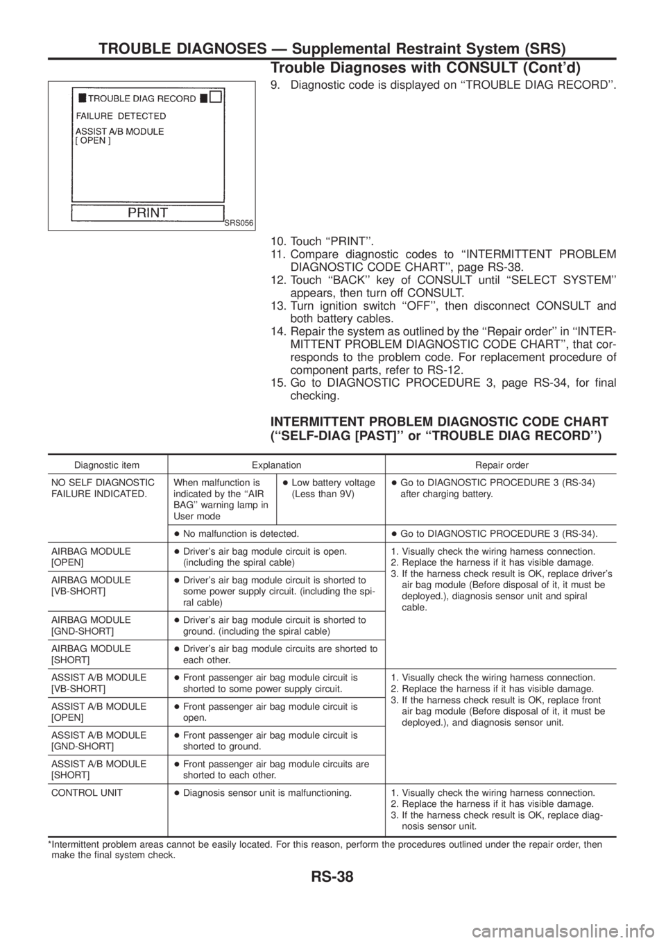
9. Diagnostic code is displayed on ``TROUBLE DIAG RECORD''.
10. Touch ``PRINT''.
11. Compare diagnostic codes to ``INTERMITTENT PROBLEM
DIAGNOSTIC CODE CHART'', page RS-38.
12. Touch ``BACK'' key of CONSULT until ``SELECT SYSTEM''
appears, then turn off CONSULT.
13. Turn ignition switch ``OFF'', then disconnect CONSULT and
both battery cables.
14. Repair the system as outlined by the ``Repair order'' in ``INTER-
MITTENT PROBLEM DIAGNOSTIC CODE CHART'', that cor-
responds to the problem code. For replacement procedure of
component parts, refer to RS-12.
15. Go to DIAGNOSTIC PROCEDURE 3, page RS-34, for ®nal
checking.
INTERMITTENT PROBLEM DIAGNOSTIC CODE CHART
(``SELF-DIAG [PAST]'' or ``TROUBLE DIAG RECORD'')
Diagnostic item Explanation Repair order
NO SELF DIAGNOSTIC
FAILURE INDICATED.When malfunction is
indicated by the ``AIR
BAG'' warning lamp in
User mode+Low battery voltage
(Less than 9V)+Go to DIAGNOSTIC PROCEDURE 3 (RS-34)
after charging battery.
+No malfunction is detected.+Go to DIAGNOSTIC PROCEDURE 3 (RS-34).
AIRBAG MODULE
[OPEN]+Driver's air bag module circuit is open.
(including the spiral cable)1. Visually check the wiring harness connection.
2. Replace the harness if it has visible damage.
3. If the harness check result is OK, replace driver's
air bag module (Before disposal of it, it must be
deployed.), diagnosis sensor unit and spiral
cable. AIRBAG MODULE
[VB-SHORT]+Driver's air bag module circuit is shorted to
some power supply circuit. (including the spi-
ral cable)
AIRBAG MODULE
[GND-SHORT]+Driver's air bag module circuit is shorted to
ground. (including the spiral cable)
AIRBAG MODULE
[SHORT]+Driver's air bag module circuits are shorted to
each other.
ASSIST A/B MODULE
[VB-SHORT]+Front passenger air bag module circuit is
shorted to some power supply circuit.1. Visually check the wiring harness connection.
2. Replace the harness if it has visible damage.
3. If the harness check result is OK, replace front
air bag module (Before disposal of it, it must be
deployed.), and diagnosis sensor unit. ASSIST A/B MODULE
[OPEN]+Front passenger air bag module circuit is
open.
ASSIST A/B MODULE
[GND-SHORT]+Front passenger air bag module circuit is
shorted to ground.
ASSIST A/B MODULE
[SHORT]+Front passenger air bag module circuits are
shorted to each other.
CONTROL UNIT+Diagnosis sensor unit is malfunctioning. 1. Visually check the wiring harness connection.
2. Replace the harness if it has visible damage.
3. If the harness check result is OK, replace diag-
nosis sensor unit.
*Intermittent problem areas cannot be easily located. For this reason, perform the procedures outlined under the repair order, then
make the ®nal system check.
SRS056
TROUBLE DIAGNOSES Ð Supplemental Restraint System (SRS)
Trouble Diagnoses with CONSULT (Cont'd)
RS-38