2006 NISSAN PATROL bulb
[x] Cancel search: bulbPage 949 of 1226
A
A/C HFC134a (R134a) system service
procedure ..................................................HA-112
A/C HFC134a system service equip-
ment precaution ............................................HA-9
A/C air ¯ow .....................................................HA-13
A/C component layout ....................................HA-12
A/C compressor precaution..............................HA-6
A/C compressor special service tool ...........HA-6, 7
A/C control linkage adjustment (auto
A/C).............................................................HA-77
A/C control operation (manual A/C) ...............HA-16
A/C harness layout (manual A/C) ..................HA-17
A/C lubricant (R134a) ...................................HA-114
A/C relay.........................................................HA-97
A/C self-diagnoses (auto A/C)........................HA-63
A/CCUT - Wiring diagram ............................EC-186
A/T control ....................................................EC-174
ABS sensor rotor ............................................FA-15
ACC/SW - Wiring diagram ...........................EC-105
ACL/SW - Wiring diagram ............................EC-164
ADJRES - Wiring diagram .............................EC-91
APS - Wiring diagram ..................................EC-138
AT/C - Wiring diagram..................................EC-174
AUDIO - Wiring diagram ...............................EL-168
Accelerator position sensor ..........................EC-138
Accelerator position switch...........................EC-164
Accelerator switch (F/C) ...............................EC-105
Adjustment resistor.........................................EC-91
Air bag disposal..............................................RS-17
Air bag ..............................................................RS-8
Air bleeding (hydraulic clutch) ..........................CL-6
Air bleeding for brake system ..........................BR-4
Air cleaner ®lter replacement .........................MA-18
Air conditioner cut control ..............................EC-19
Air ¯ow meter - See Mass air ¯ow
sensor .........................................................EC-73
Air mix door control linkage
adjustment ................................................HA-81
Alternator.........................................................EL-56
Antenna - See Power antenna .....................EL-181
Audio and A/C control removal and
installation - See Instrument panel .............BT-11
Audio .............................................................EL-168
Auto lock free running hub .............................FA-13
Automatic ampli®er .........................................HA-61
Axle housing (rear) ...........................................RA-9
B
BACK/L - Wiring diagram................................EL-78
Back door opener - See Back door ..................BT-6
Back door trim.................................................BT-24
Back door window...........................................BT-45
Back door ..........................................................BT-6Back-up lamp switch (M/T) ..............................MT-4
Back-up lamp ..................................................EL-78
Battery .............................................................EL-37
Baulk ring (M/T)..............................................MT-10
Body alignment ...............................................BT-49
Body mounting ................................................BT-48
Brake booster .................................................BR-15
Brake ¯uid change ...........................................BR-3
Brake ¯uid level and line check .......................BR-3
Brake ¯uid level .............................................MA-23
Brake hydraulic line ..........................................BR-5
Brake inspection ............................................MA-24
Brake master cylinder ....................................BR-12
Brake pedal ....................................................BR-10
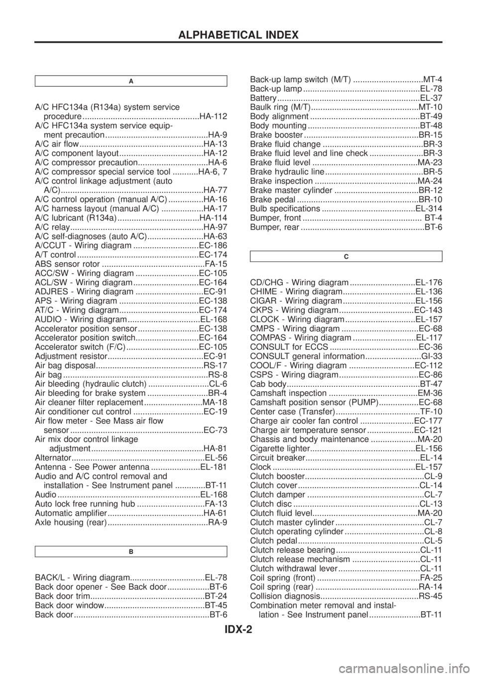
Bulb speci®cations ........................................EL-314
Bumper, front ................................................... BT-4
Bumper, rear .....................................................BT-6
C
CD/CHG - Wiring diagram ............................EL-176
CHIME - Wiring diagram...............................EL-136
CIGAR - Wiring diagram ...............................EL-156
CKPS - Wiring diagram ................................EC-143
CLOCK - Wiring diagram ..............................EL-157
CMPS - Wiring diagram .................................EC-68
COMPAS - Wiring diagram ...........................EL-117
CONSULT for ECCS ......................................EC-36
CONSULT general information ........................GI-33
COOL/F - Wiring diagram ............................EC-112
CSPS - Wiring diagram ..................................EC-86
Cab body.........................................................BT-47
Camshaft inspection ......................................EM-36
Camshaft position sensor (PUMP).................EC-68
Center case (Transfer) ....................................TF-10
Charge air cooler fan control .......................EC-177
Charge air temperature sensor ....................EC-121
Chassis and body maintenance ....................MA-20
Cigarette lighter.............................................EL-156
Circuit breaker.................................................EL-14
Clock .............................................................EL-157
Clutch booster...................................................CL-9
Clutch cover ....................................................CL-14
Clutch damper ..................................................CL-7
Clutch disc ......................................................CL-13
Clutch ¯uid level.............................................MA-20
Clutch master cylinder ......................................CL-7
Clutch operating cylinder ..................................CL-8
Clutch pedal ......................................................CL-5
Clutch release bearing ....................................CL-11
Clutch release mechanism .............................CL-11
Clutch withdrawal lever ...................................CL-11
Coil spring (front) ............................................FA-25
Coil spring (rear) ............................................RA-14
Collision diagnosis..........................................RS-45
Combination meter removal and instal-
lation - See Instrument panel ......................BT-11
ALPHABETICAL INDEX
IDX-2
Page 1118 of 1226
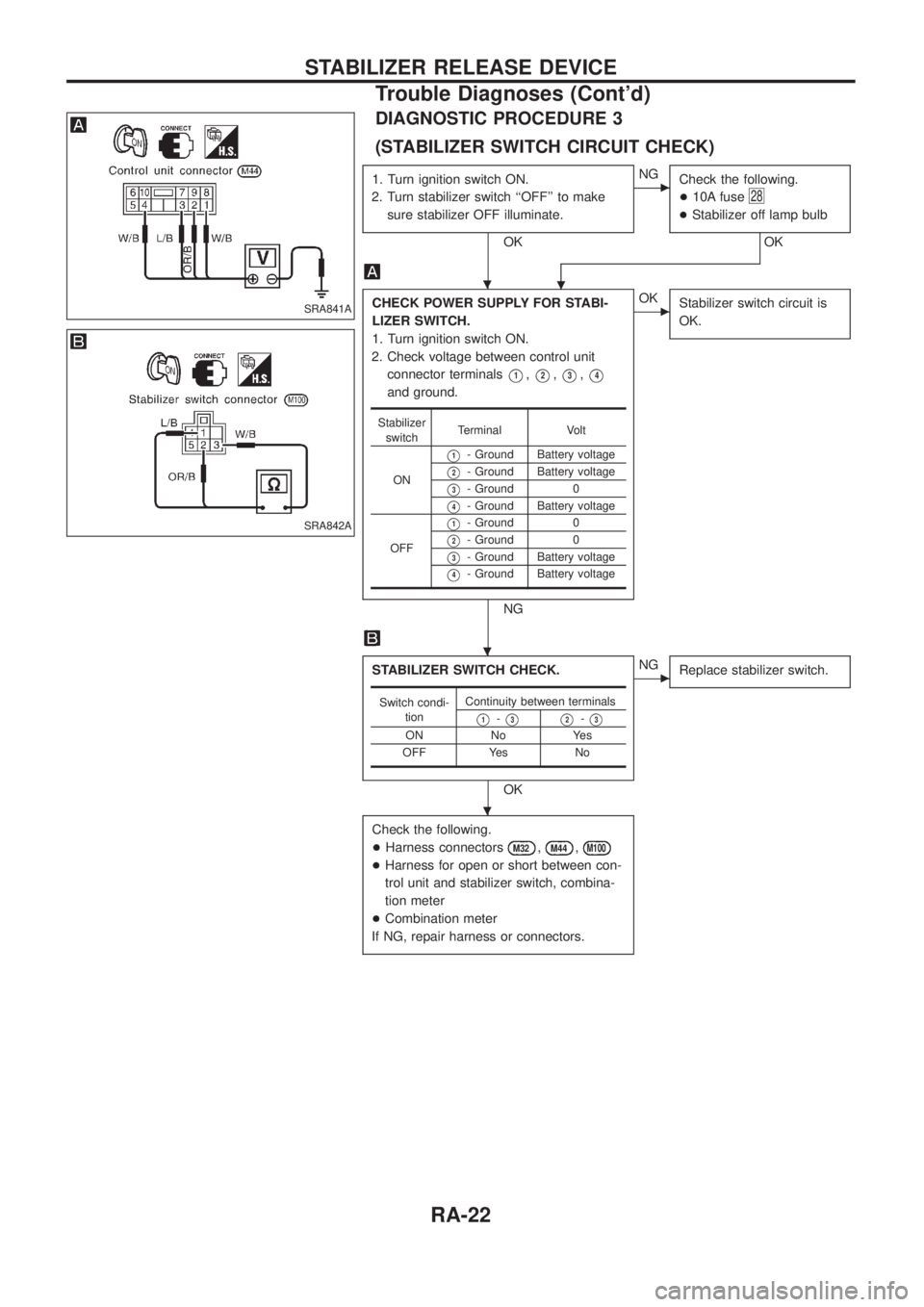
DIAGNOSTIC PROCEDURE 3
(STABILIZER SWITCH CIRCUIT CHECK)
1. Turn ignition switch ON.
2. Turn stabilizer switch ``OFF'' to make
sure stabilizer OFF illuminate.
OK
cNG
Check the following.
+10A fuse
28
+Stabilizer off lamp bulb
OK
.
CHECK POWER SUPPLY FOR STABI-
LIZER SWITCH.
1. Turn ignition switch ON.
2. Check voltage between control unit
connector terminals
V1,V2,V3,V4
and ground.
NG
cOK
Stabilizer switch circuit is
OK.
STABILIZER SWITCH CHECK.
OK
cNG
Replace stabilizer switch.
Check the following.
+Harness connectors
M32,M44,M100
+Harness for open or short between con-
trol unit and stabilizer switch, combina-
tion meter
+Combination meter
If NG, repair harness or connectors.
Stabilizer
switchTerminal Volt
ON
V1- Ground Battery voltage
V2- Ground Battery voltage
V3- Ground 0
V4- Ground Battery voltage
OFF
V1- Ground 0
V2- Ground 0
V3- Ground Battery voltage
V4- Ground Battery voltage
Switch condi-
tionContinuity between terminals
V1-V3V2-V3
ON No Yes
OFF Yes No
SRA841A
SRA842A
.
.
.
STABILIZER RELEASE DEVICE
Trouble Diagnoses (Cont'd)
RA-22
Page 1133 of 1226
Maintenance Items
CAUTION:
Do not use a circuit tester to check SRS circuit.
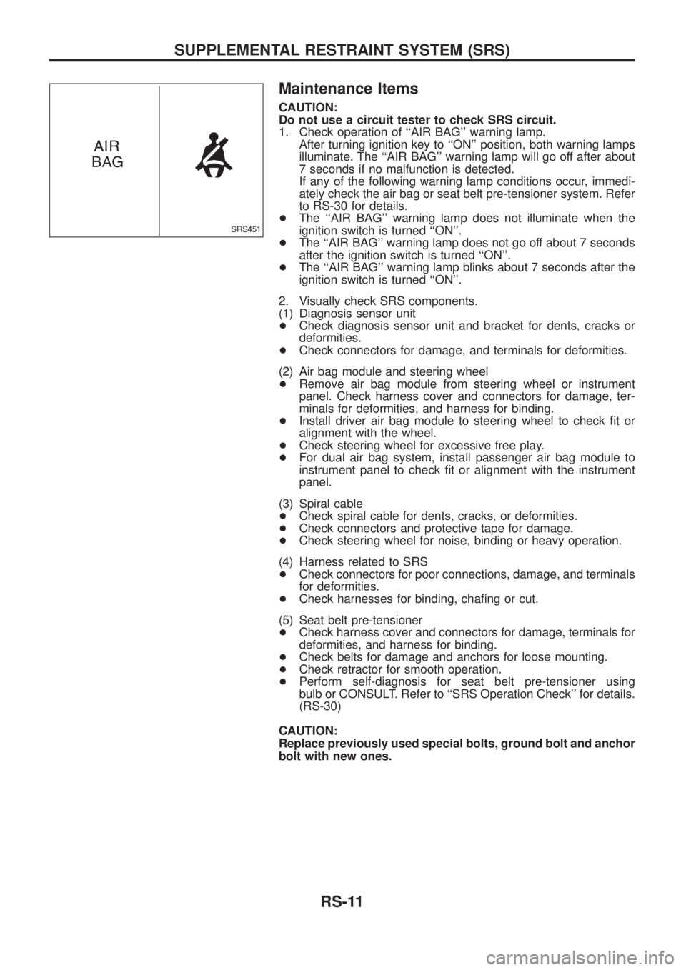
1. Check operation of ``AIR BAG'' warning lamp.
After turning ignition key to ``ON'' position, both warning lamps
illuminate. The ``AIR BAG'' warning lamp will go off after about
7 seconds if no malfunction is detected.
If any of the following warning lamp conditions occur, immedi-
ately check the air bag or seat belt pre-tensioner system. Refer
to RS-30 for details.
+The ``AIR BAG'' warning lamp does not illuminate when the
ignition switch is turned ``ON''.
+The ``AIR BAG'' warning lamp does not go off about 7 seconds
after the ignition switch is turned ``ON''.
+The ``AIR BAG'' warning lamp blinks about 7 seconds after the
ignition switch is turned ``ON''.
2. Visually check SRS components.
(1) Diagnosis sensor unit
+Check diagnosis sensor unit and bracket for dents, cracks or
deformities.
+Check connectors for damage, and terminals for deformities.
(2) Air bag module and steering wheel
+Remove air bag module from steering wheel or instrument
panel. Check harness cover and connectors for damage, ter-
minals for deformities, and harness for binding.
+Install driver air bag module to steering wheel to check ®t or
alignment with the wheel.
+Check steering wheel for excessive free play.
+For dual air bag system, install passenger air bag module to
instrument panel to check ®t or alignment with the instrument
panel.
(3) Spiral cable
+Check spiral cable for dents, cracks, or deformities.
+Check connectors and protective tape for damage.
+Check steering wheel for noise, binding or heavy operation.
(4) Harness related to SRS
+Check connectors for poor connections, damage, and terminals
for deformities.
+Check harnesses for binding, cha®ng or cut.
(5) Seat belt pre-tensioner
+Check harness cover and connectors for damage, terminals for
deformities, and harness for binding.
+Check belts for damage and anchors for loose mounting.
+Check retractor for smooth operation.
+Perform self-diagnosis for seat belt pre-tensioner using
bulb or CONSULT. Refer to ``SRS Operation Check'' for details.
(RS-30)
CAUTION:
Replace previously used special bolts, ground bolt and anchor
bolt with new ones.
SRS451
SUPPLEMENTAL RESTRAINT SYSTEM (SRS)
RS-11
Page 1147 of 1226
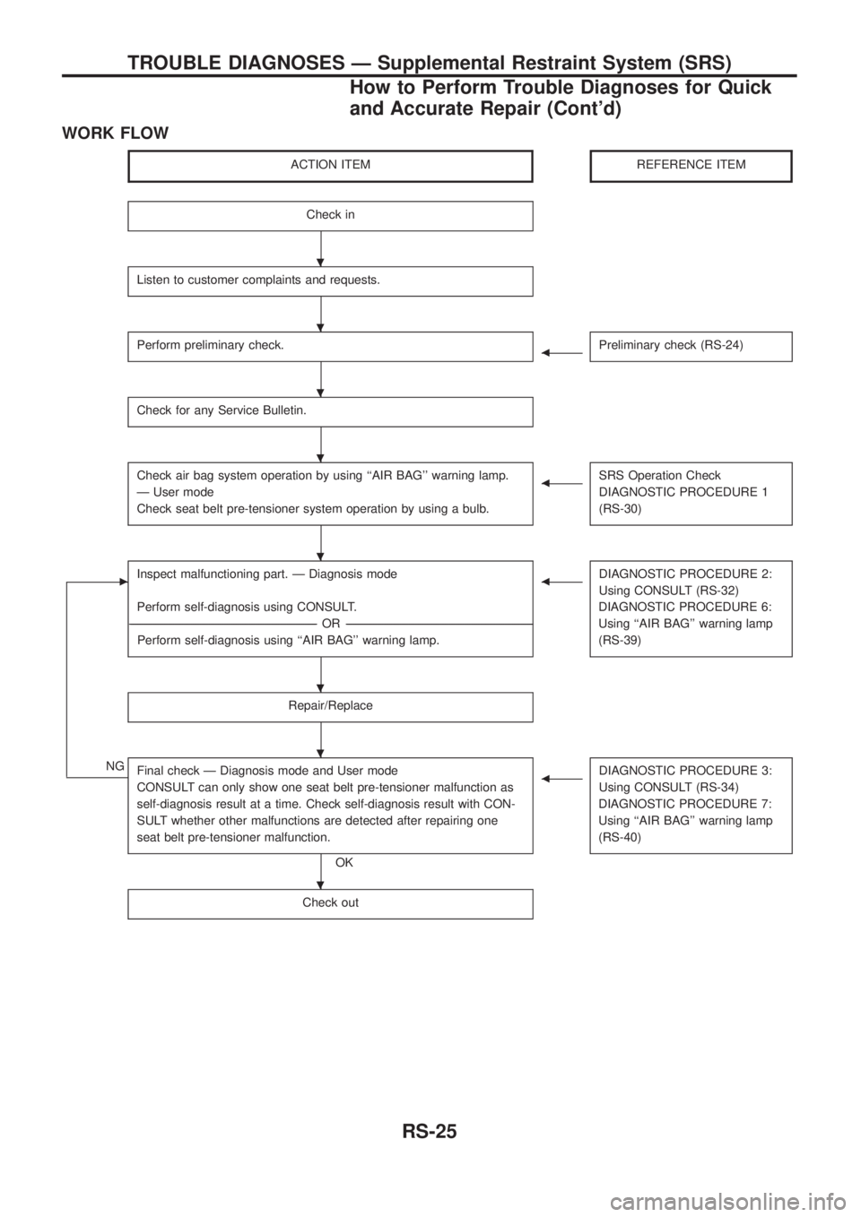
WORK FLOW
ACTION ITEMREFERENCE ITEM
Check in
Listen to customer complaints and requests.
Perform preliminary check.bPreliminary check (RS-24)
Check for any Service Bulletin.
Check air bag system operation by using ``AIR BAG'' warning lamp.
Ð User mode
Check seat belt pre-tensioner system operation by using a bulb.bSRS Operation Check
DIAGNOSTIC PROCEDURE 1
(RS-30)
cInspect malfunctioning part. Ð Diagnosis mode
Perform self-diagnosis using CONSULT.
----------------------------------------------------------------------------------------------------------------------------------------------------------------------------------------------------------------------------------OR ----------------------------------------------------------------------------------------------------------------------------------------------------------------------------------------------------------------------------------
Perform self-diagnosis using ``AIR BAG'' warning lamp.bDIAGNOSTIC PROCEDURE 2:
Using CONSULT (RS-32)
DIAGNOSTIC PROCEDURE 6:
Using ``AIR BAG'' warning lamp
(RS-39)
Repair/Replace
NGFinal check Ð Diagnosis mode and User mode
CONSULT can only show one seat belt pre-tensioner malfunction as
self-diagnosis result at a time. Check self-diagnosis result with CON-
SULT whether other malfunctions are detected after repairing one
seat belt pre-tensioner malfunction.
OK
bDIAGNOSTIC PROCEDURE 3:
Using CONSULT (RS-34)
DIAGNOSTIC PROCEDURE 7:
Using ``AIR BAG'' warning lamp
(RS-40)
Check out
.
.
.
.
.
.
.
.
TROUBLE DIAGNOSES Ð Supplemental Restraint System (SRS)
How to Perform Trouble Diagnoses for Quick
and Accurate Repair (Cont'd)
RS-25
Page 1153 of 1226
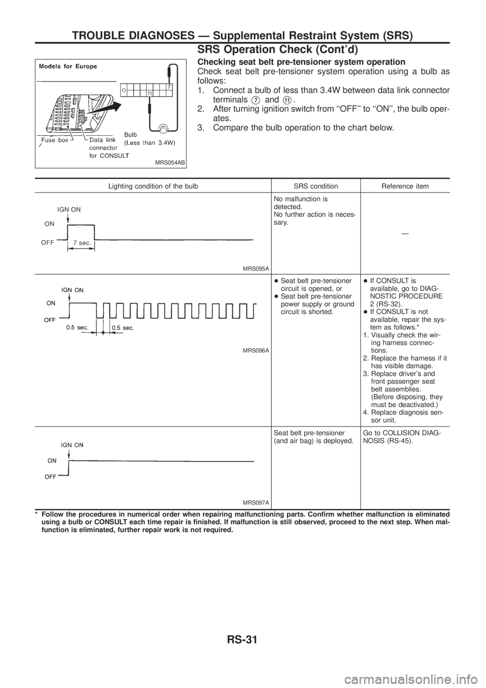
Checking seat belt pre-tensioner system operation
Check seat belt pre-tensioner system operation using a bulb as
follows:
1. Connect a bulb of less than 3.4W between data link connector
terminals
V7andV11.
2. After turning ignition switch from ``OFF'' to ``ON'', the bulb oper-
ates.
3. Compare the bulb operation to the chart below.
Lighting condition of the bulb SRS condition Reference item
MRS095A
No malfunction is
detected.
No further action is neces-
sary.
Ð
MRS096A
+Seat belt pre-tensioner
circuit is opened, or
+Seat belt pre-tensioner
power supply or ground
circuit is shorted.+If CONSULT is
available, go to DIAG-
NOSTIC PROCEDURE
2 (RS-32).
+If CONSULT is not
available, repair the sys-
tem as follows.*
1. Visually check the wir-
ing harness connec-
tions.
2. Replace the harness if it
has visible damage.
3. Replace driver's and
front passenger seat
belt assemblies.
(Before disposing, they
must be deactivated.)
4. Replace diagnosis sen-
sor unit.
MRS097A
Seat belt pre-tensioner
(and air bag) is deployed.Go to COLLISION DIAG-
NOSIS (RS-45).
* Follow the procedures in numerical order when repairing malfunctioning parts. Con®rm whether malfunction is eliminated
using a bulb or CONSULT each time repair is ®nished. If malfunction is still observed, proceed to the next step. When mal-
function is eliminated, further repair work is not required.
MRS054AB
TROUBLE DIAGNOSES Ð Supplemental Restraint System (SRS)
SRS Operation Check (Cont'd)
RS-31