2006 NISSAN PATROL timing belt
[x] Cancel search: timing beltPage 687 of 1226
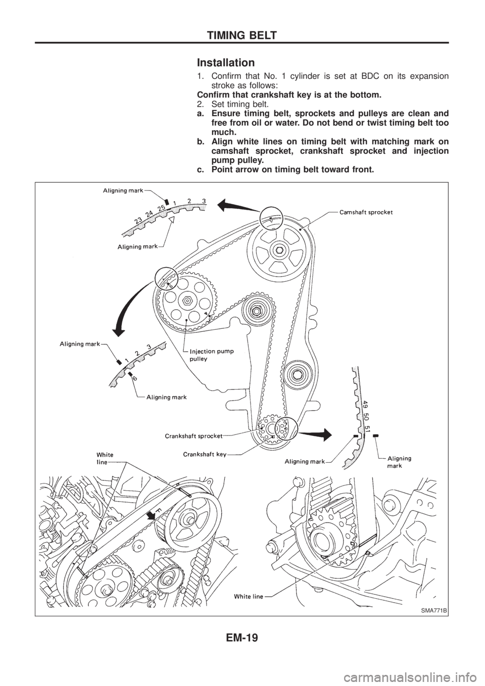
Installation
1. Con®rm that No. 1 cylinder is set at BDC on its expansion
stroke as follows:
Con®rm that crankshaft key is at the bottom.
2. Set timing belt.
a. Ensure timing belt, sprockets and pulleys are clean and
free from oil or water. Do not bend or twist timing belt too
much.
b. Align white lines on timing belt with matching mark on
camshaft sprocket, crankshaft sprocket and injection
pump pulley.
c. Point arrow on timing belt toward front.
SMA771B
TIMING BELT
EM-19
Page 688 of 1226
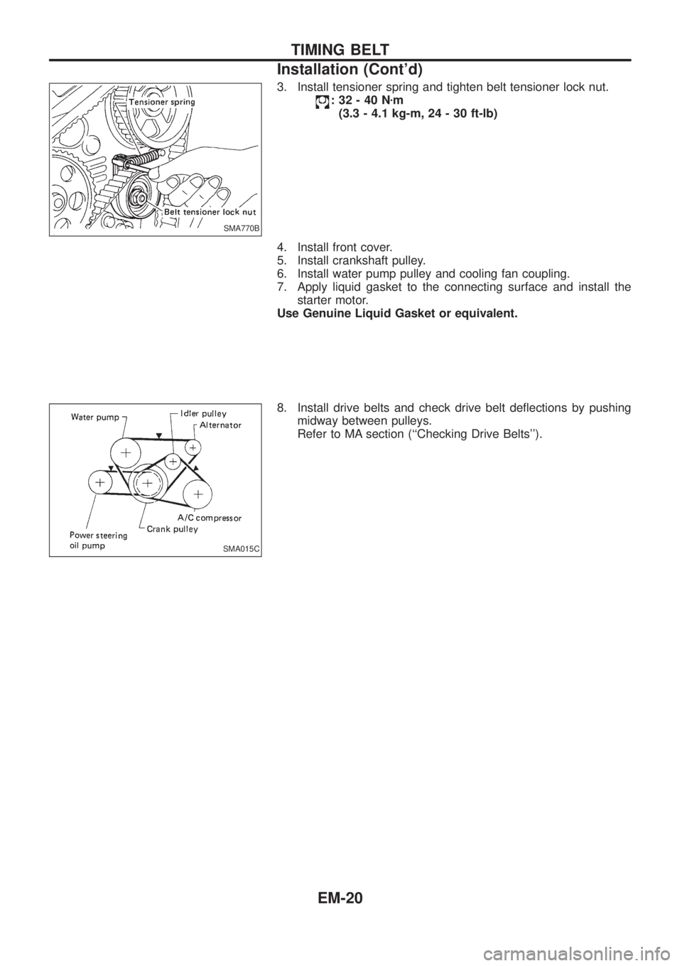
3. Install tensioner spring and tighten belt tensioner lock nut.
:32-40Nzm
(3.3 - 4.1 kg-m, 24 - 30 ft-lb)
4. Install front cover.
5. Install crankshaft pulley.
6. Install water pump pulley and cooling fan coupling.
7. Apply liquid gasket to the connecting surface and install the
starter motor.
Use Genuine Liquid Gasket or equivalent.
8. Install drive belts and check drive belt de¯ections by pushing
midway between pulleys.
Refer to MA section (``Checking Drive Belts'').
SMA770B
SMA015C
TIMING BELT
Installation (Cont'd)
EM-20
Page 689 of 1226
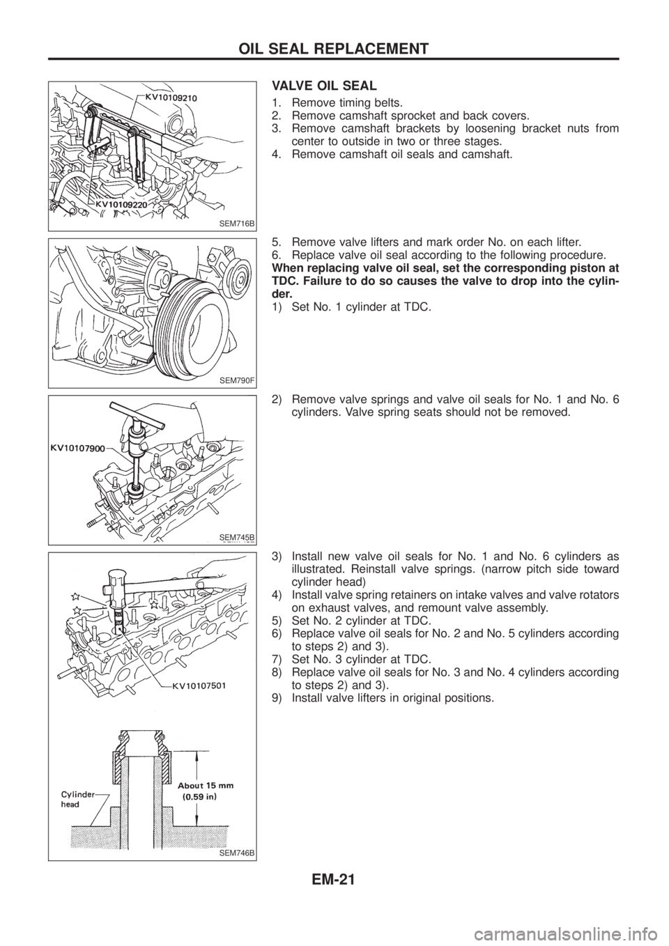
VALVE OIL SEAL
1. Remove timing belts.
2. Remove camshaft sprocket and back covers.
3. Remove camshaft brackets by loosening bracket nuts from
center to outside in two or three stages.
4. Remove camshaft oil seals and camshaft.
5. Remove valve lifters and mark order No. on each lifter.
6. Replace valve oil seal according to the following procedure.
When replacing valve oil seal, set the corresponding piston at
TDC. Failure to do so causes the valve to drop into the cylin-
der.
1) Set No. 1 cylinder at TDC.
2) Remove valve springs and valve oil seals for No. 1 and No. 6
cylinders. Valve spring seats should not be removed.
3) Install new valve oil seals for No. 1 and No. 6 cylinders as
illustrated. Reinstall valve springs. (narrow pitch side toward
cylinder head)
4) Install valve spring retainers on intake valves and valve rotators
on exhaust valves, and remount valve assembly.
5) Set No. 2 cylinder at TDC.
6) Replace valve oil seals for No. 2 and No. 5 cylinders according
to steps 2) and 3).
7) Set No. 3 cylinder at TDC.
8) Replace valve oil seals for No. 3 and No. 4 cylinders according
to steps 2) and 3).
9) Install valve lifters in original positions.
SEM716B
SEM790F
SEM745B
SEM746B
OIL SEAL REPLACEMENT
EM-21
Page 690 of 1226
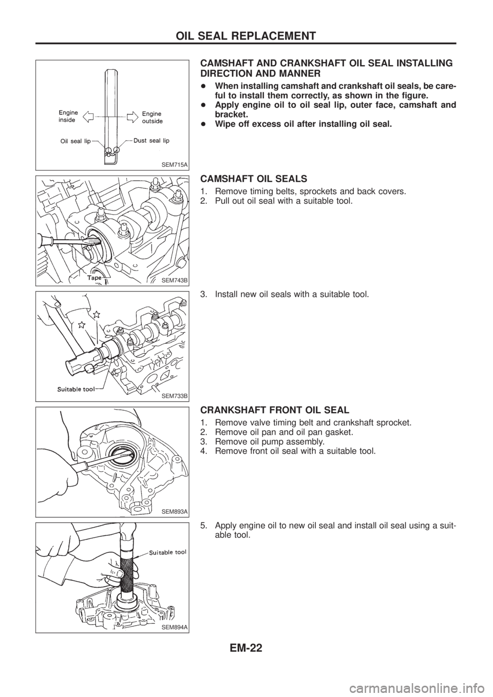
CAMSHAFT AND CRANKSHAFT OIL SEAL INSTALLING
DIRECTION AND MANNER
+When installing camshaft and crankshaft oil seals, be care-
ful to install them correctly, as shown in the ®gure.
+Apply engine oil to oil seal lip, outer face, camshaft and
bracket.
+Wipe off excess oil after installing oil seal.
CAMSHAFT OIL SEALS
1. Remove timing belts, sprockets and back covers.
2. Pull out oil seal with a suitable tool.
3. Install new oil seals with a suitable tool.
CRANKSHAFT FRONT OIL SEAL
1. Remove valve timing belt and crankshaft sprocket.
2. Remove oil pan and oil pan gasket.
3. Remove oil pump assembly.
4. Remove front oil seal with a suitable tool.
5. Apply engine oil to new oil seal and install oil seal using a suit-
able tool.
SEM715A
SEM743B
SEM733B
SEM893A
SEM894A
OIL SEAL REPLACEMENT
EM-22
Page 698 of 1226
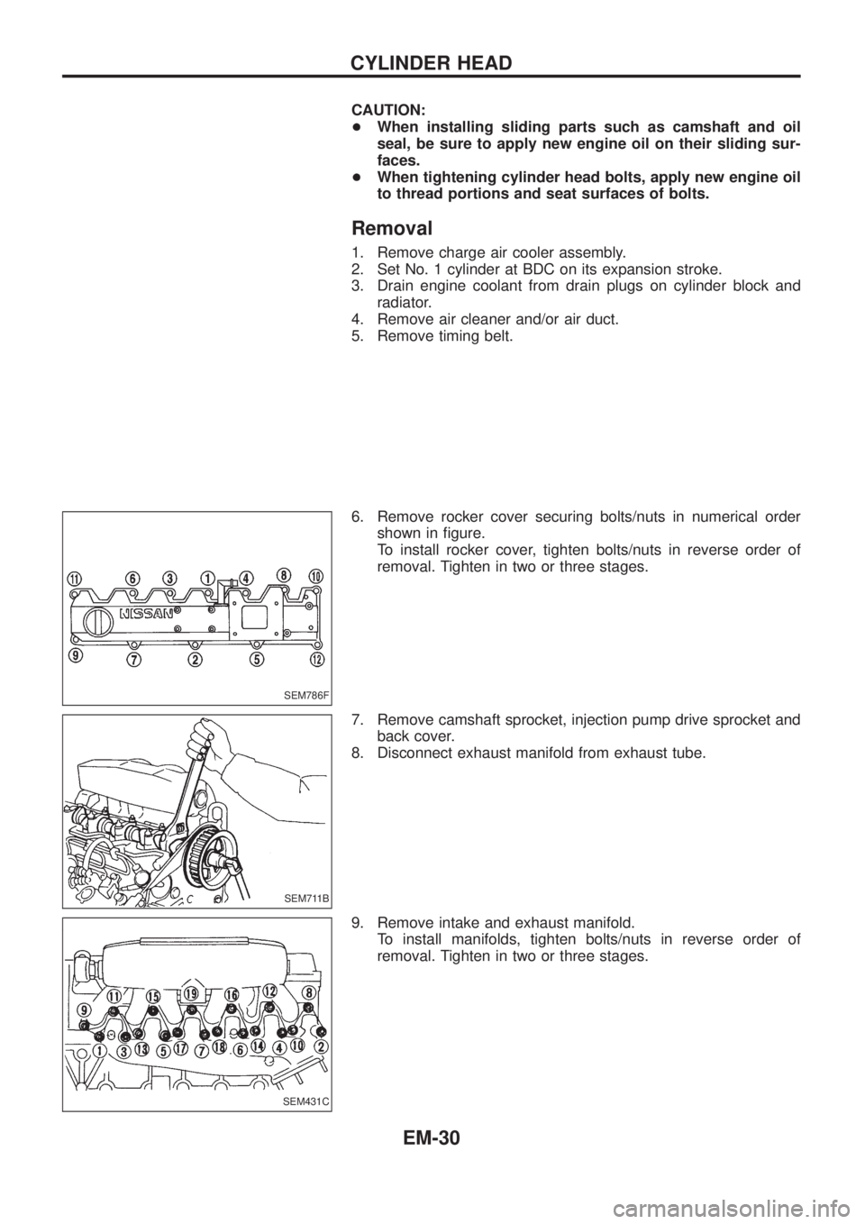
CAUTION:
+When installing sliding parts such as camshaft and oil
seal, be sure to apply new engine oil on their sliding sur-
faces.
+When tightening cylinder head bolts, apply new engine oil
to thread portions and seat surfaces of bolts.
Removal
1. Remove charge air cooler assembly.
2. Set No. 1 cylinder at BDC on its expansion stroke.
3. Drain engine coolant from drain plugs on cylinder block and
radiator.
4. Remove air cleaner and/or air duct.
5. Remove timing belt.
6. Remove rocker cover securing bolts/nuts in numerical order
shown in ®gure.
To install rocker cover, tighten bolts/nuts in reverse order of
removal. Tighten in two or three stages.
7. Remove camshaft sprocket, injection pump drive sprocket and
back cover.
8. Disconnect exhaust manifold from exhaust tube.
9. Remove intake and exhaust manifold.
To install manifolds, tighten bolts/nuts in reverse order of
removal. Tighten in two or three stages.
SEM786F
SEM711B
SEM431C
CYLINDER HEAD
EM-30
Page 708 of 1226
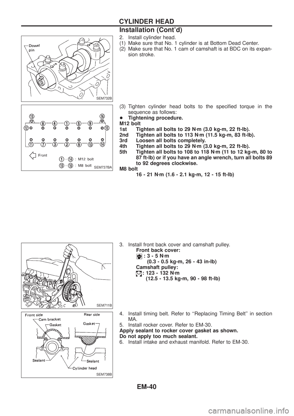
2. Install cylinder head.
(1) Make sure that No. 1 cylinder is at Bottom Dead Center.
(2) Make sure that No. 1 cam of camshaft is at BDC on its expan-
sion stroke.
(3) Tighten cylinder head bolts to the speci®ed torque in the
sequence as follows:
+Tightening procedure.
M12 bolt
1st Tighten all bolts to 29 Nzm (3.0 kg-m, 22 ft-lb).
2nd Tighten all bolts to 113 Nzm (11.5 kg-m, 83 ft-lb).
3rd Loosen all bolts completely.
4th Tighten all bolts to 29 Nzm (3.0 kg-m, 22 ft-lb).
5th Tighten all bolts to 108 to 118 Nzm (11 to 12 kg-m, 80 to
87 ft-lb) or if you have an angle wrench, turn all bolts 89
to 92 degrees clockwise.
M8 bolt
16-21Nzm (1.6 - 2.1 kg-m, 12 - 15 ft-lb)
3. Install front back cover and camshaft pulley.
Front back cover:
:3-5Nzm
(0.3 - 0.5 kg-m, 26 - 43 in-lb)
Camshaft pulley:
: 123 - 132 Nzm
(12.5 - 13.5 kg-m, 90 - 98 ft-lb)
4. Install timing belt. Refer to ``Replacing Timing Belt'' in section
MA.
5. Install rocker cover. Refer to EM-30.
Apply sealant to rocker cover gasket as shown.
Do not apply too much sealant.
6. Install intake and exhaust manifold. Refer to EM-30.
SEM732B
SEM737BA
SEM711B
SEM738B
CYLINDER HEAD
Installation (Cont'd)
EM-40
Page 715 of 1226
CAUTION:
+When installing sliding parts such as bearings and
pistons, apply engine oil to the sliding surfaces.
+Place removed parts, such as bearings and bearing caps,
in their proper order and direction.
+When installing connecting rod bolts and main bearing cap
bolts, apply new engine oil to threads and seating surfaces
of nuts.
+Do not allow any magnetic materials to contact the ring
gear teeth of drive plate.
Disassembly
PISTON AND CRANKSHAFT
1. Place engine on a work stand.
2. Remove timing belt and injection pump.
3. Drain coolant and remove water pump.
4. Remove front cover.
5. Drain oil.
6. Remove oil pan and oil pump.
7. Remove cylinder head.
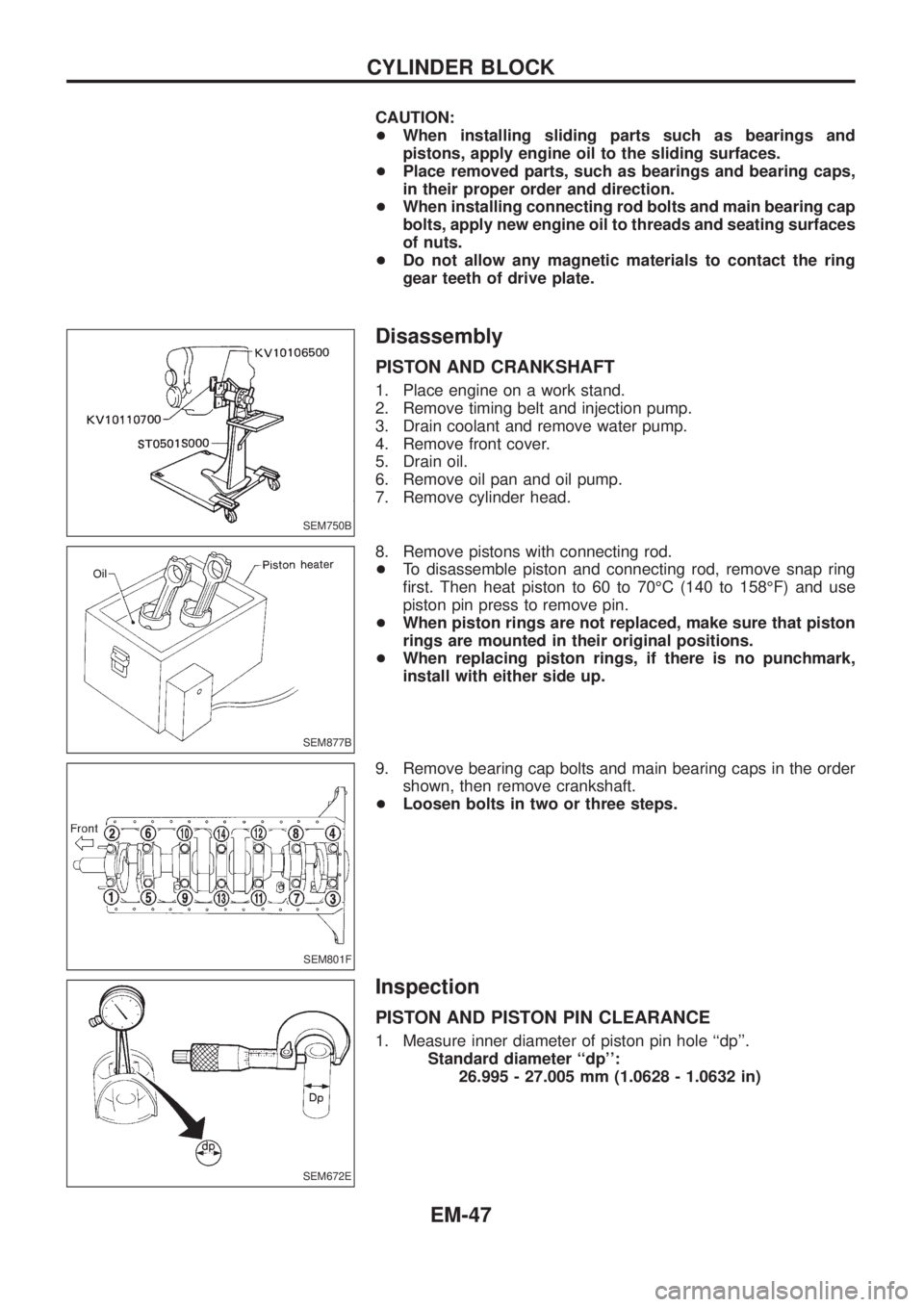
8. Remove pistons with connecting rod.
+To disassemble piston and connecting rod, remove snap ring
®rst. Then heat piston to 60 to 70ÉC (140 to 158ÉF) and use
piston pin press to remove pin.
+When piston rings are not replaced, make sure that piston
rings are mounted in their original positions.
+When replacing piston rings, if there is no punchmark,
install with either side up.
9. Remove bearing cap bolts and main bearing caps in the order
shown, then remove crankshaft.
+Loosen bolts in two or three steps.
Inspection
PISTON AND PISTON PIN CLEARANCE
1. Measure inner diameter of piston pin hole ``dp''.
Standard diameter ``dp'':
26.995 - 27.005 mm (1.0628 - 1.0632 in)
SEM750B
SEM877B
SEM801F
SEM672E
CYLINDER BLOCK
EM-47
Page 951 of 1226

Front drive shaft (Transfer) .............................TF-11
Front ®nal drive disassembly (4WD) ..............PD-14
Front ®nal drive removal and installa-
tion (4WD)...................................................PD-11
Front passenger air bag.............................RS-8, 14
Front seat belt ..................................................RS-2
Front seat ........................................................BT-32
Front suspension ............................................FA-24
Front washer .................................................EL-141
Front wiper ....................................................EL-141
Fuel cut control (at no load & high
engine speed) .............................................EC-20
Fuel cut solenoid valve ................................EC-129
Fuel ®ller lid.......................................................BT-6
Fuel ®lter replacement ...................................MA-16
Fuel gauge ....................................................EL-102
Fuel injection system......................................EC-15
Fuel line inspection ........................................MA-17
Fuel precautions ................................................GI-5
Fuel temperature sensor ..............................EC-134
Fuse block.....................................................EL-319
Fuse ................................................................EL-14
Fusible link ......................................................EL-14
G
GLOW - Wiring diagram...............................EC-150
GOVNR - Wiring diagram ..............................EC-95
Garage jack and safety stand .........................GI-39
Gauges..........................................................EL-102
Gear components (M/T) .................................MT-10
Glass .................................................................BT-9
Glow plug .............................................EC-150, 154
Glow relay ............................................EC-150, 154
Grease .............................................................MA-9
Ground distribution..........................................EL-15
H
H/AIM - Wiring diagram ..................................EL-71
H/LAMP - Wiring diagram ...............................EL-61
HEAT UP - Wiring diagram ..........................EC-182
HFC134a (R134a) system service
procedure ..................................................HA-112
HLC - Wiring diagram ...................................EL-153
HORN - Wiring diagram................................EL-155
Harness connector inspection .........................GI-17
Harness connector ............................................EL-2
Harness layout ..............................................EL-275
Headlamp aiming control ................................EL-70
Headlamp leveler - See Headlamp
aiming control ..............................................EL-70
Headlamp wiper ............................................EL-153
Headlamp ........................................................EL-61
Headlining - See Roof trim .............................BT-20
Heat up switch..............................................EC-182
Heated seat.....................................................BT-34Hood..................................................................BT-4
Horn ..............................................................EL-155
How to erase DTC for ECCS OBD
system ........................................................EC-30
I
IATS - Wiring diagram ..................................EC-121
IC/FAN - Wiring diagram ..............................EC-177
ILL - Wiring diagram .......................................EL-87
INT/L - Wiring diagram..................................EL-101
Identi®cation plate............................................GI-37
Idle speed inspection .....................................MA-19
Idle speed .......................................................EC-46
Illumination ......................................................EL-86
In vehicle sensor ..........................................HA-105
Injection nozzle inspection .............................MA-18
Injection nozzle...............................................EC-22
Injection timing control valve ........................EC-100
Instrument panel .............................................BT-11
Intake door control linkage adjustment ..........HA-84
Intake door motor ...........................................HA-25
Intake sensor ................................................HA-111
Interior lamp ....................................................EL-93
Interior .............................................................BT-14
J
Jacking points ..................................................GI-39
Joint connector (J/C).....................................EL-322
Journal bearing assembly (propeller
shaft) .............................................................PD-8
Journal bearing disassembly (propeller
shaft) .............................................................PD-7
Junction box (J/B) .........................................EL-319
L
LSV (Load sensing valve) ................................BR-6
Lifting points ....................................................GI-40
Limited slip diff. adjustment............................PD-23
Limited slip diff. assembly ..............................PD-24
Limited slip diff. disassembly .........................PD-21
Limited slip diff. inspection .............................PD-21
Location of electrical units ............................EL-269
Lock, door .........................................................BT-9
Lubricant (R134a) A/C ..................................HA-114
Lubricants.........................................................MA-9
Lubrication circuit (engine) ...............................LC-3
Lubrication-locks, hinges and hood
latches ........................................................MA-27
Luggage compartment trim .............................BT-14
Luggage room lamp ........................................EL-93
ALPHABETICAL INDEX
IDX-4