2006 NISSAN PATROL main
[x] Cancel search: mainPage 935 of 1226
Maintenance of Lubricant Quantity in
Compressor
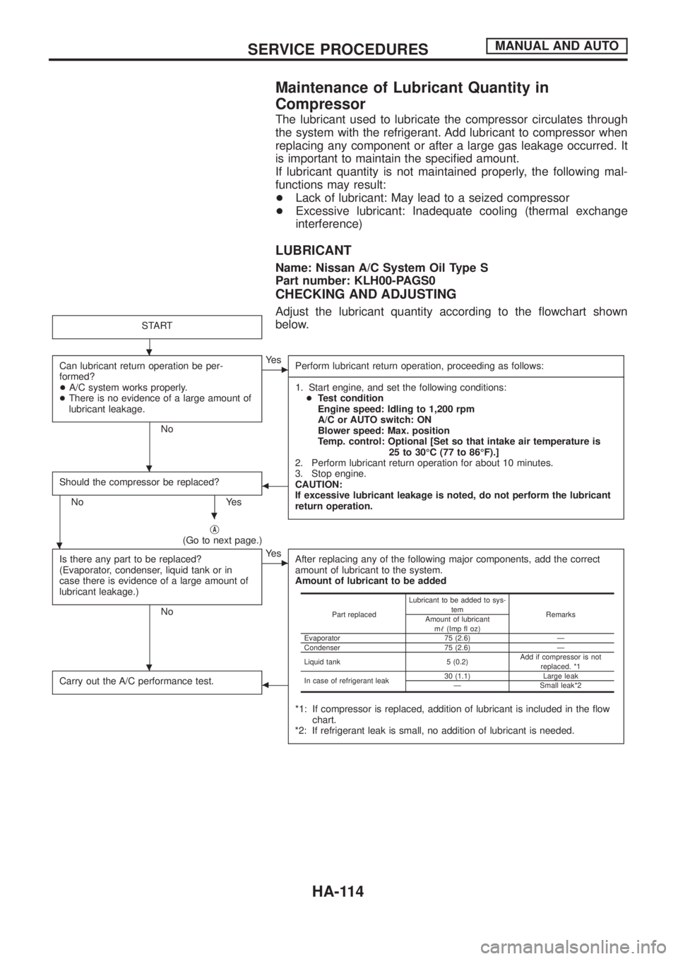
The lubricant used to lubricate the compressor circulates through
the system with the refrigerant. Add lubricant to compressor when
replacing any component or after a large gas leakage occurred. It
is important to maintain the speci®ed amount.
If lubricant quantity is not maintained properly, the following mal-
functions may result:
+Lack of lubricant: May lead to a seized compressor
+Excessive lubricant: Inadequate cooling (thermal exchange
interference)
LUBRICANT
Name: Nissan A/C System Oil Type S
Part number: KLH00-PAGS0
CHECKING AND ADJUSTING
Adjust the lubricant quantity according to the ¯owchart shown
below.
START
Can lubricant return operation be per-
formed?
+A/C system works properly.
+There is no evidence of a large amount of
lubricant leakage.
No
cYe s
Perform lubricant return operation, proceeding as follows:
------------------------------------------------------------------------------------------------------------------------------------------------------------------------------------------------------------------------------------------------------------------------------------------------------------------------------------------------------------------------------------------------------------------------------------------------------------------------------------------------------------------------------------
1. Start engine, and set the following conditions:
+Test condition
Engine speed: Idling to 1,200 rpm
A/C or AUTO switch: ON
Blower speed: Max. position
Temp. control: Optional [Set so that intake air temperature is
25 to 30ÉC (77 to 86ÉF).]
2. Perform lubricant return operation for about 10 minutes.
3. Stop engine.
CAUTION:
If excessive lubricant leakage is noted, do not perform the lubricant
return operation.
Should the compressor be replaced?
No Yes
b
jA(Go to next page.)
Is there any part to be replaced?
(Evaporator, condenser, liquid tank or in
case there is evidence of a large amount of
lubricant leakage.)
No
cYe s
After replacing any of the following major components, add the correct
amount of lubricant to the system.
Amount of lubricant to be added
*1: If compressor is replaced, addition of lubricant is included in the ¯ow
chart.
*2: If refrigerant leak is small, no addition of lubricant is needed.
Carry out the A/C performance test.b
Part replacedLubricant to be added to sys-
tem
Remarks
Amount of lubricant
m!(Imp ¯ oz)
Evaporator 75 (2.6) Ð
Condenser 75 (2.6) Ð
Liquid tank 5 (0.2)Add if compressor is not
replaced. *1
In case of refrigerant leak30 (1.1) Large leak
Ð Small leak*2
.
.
.
.
.
SERVICE PROCEDURESMANUAL AND AUTO
HA-114
Page 936 of 1226
jA
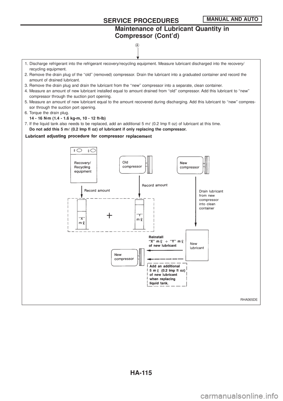
1. Discharge refrigerant into the refrigerant recovery/recycling equipment. Measure lubricant discharged into the recovery/
recycling equipment.
2. Remove the drain plug of the ``old'' (removed) compressor. Drain the lubricant into a graduated container and record the
amount of drained lubricant.
3. Remove the drain plug and drain the lubricant from the ``new'' compressor into a separate, clean container.
4. Measure an amount of new lubricant installed equal to amount drained from ``old'' compressor. Add this lubricant to ``new''
compressor through the suction port opening.
5. Measure an amount of new lubricant equal to the amount recovered during discharging. Add this lubricant to ``new'' compres-
sor through the suction port opening.
6. Torque the drain plug.
14-16Nzm (1.4 - 1.6 kg-m, 10 - 12 ft-lb)
7. If the liquid tank also needs to be replaced, add an additional 5 m!(0.2 Imp ¯ oz) of lubricant at this time.
Do not add this 5 m!(0.2 Imp ¯ oz) of lubricant if only replacing the compressor.
RHA065DE
.
SERVICE PROCEDURESMANUAL AND AUTO
Maintenance of Lubricant Quantity in
Compressor (Cont'd)
HA-115
Page 937 of 1226

Ventilation Air Filter
FUNCTION
Air inside passenger compartment is kept clean at either recircula-
tion or fresh mode by installing ventilation air ®lter into cooling unit.
REPLACEMENT TIMING
Replace ventilation air ®lter.
Refer to ``PERIODIC MAINTENANCE'' in MA section.
Caution label is ®xed inside the glove box.
REPLACEMENT PROCEDURES
+Remove glove box.
+Remove instrument reinforcement from instrument panel.
+Remove ventilation air ®lter ®xed clip.
+Take out ventilation air ®lter from cooling unit.
+Replace with new one and reinstall on cooling unit.
+Reinstall instrument reinforcement, glove box and undercover.
RHA042G
SHA868E
RHA953F
SERVICE PROCEDURESMANUAL AND AUTO
HA-116
Page 940 of 1226
Checking Refrigerant Leaks
PRELIMINARY CHECK
Perform a visual inspection of all refrigeration parts, ®ttings, hoses,
and components for signs of A/C lubricant leakage, damage and
corrosion.
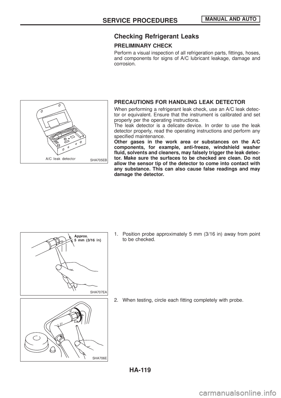
PRECAUTIONS FOR HANDLING LEAK DETECTOR
When performing a refrigerant leak check, use an A/C leak detec-
tor or equivalent. Ensure that the instrument is calibrated and set
properly per the operating instructions.
The leak detector is a delicate device. In order to use the leak
detector properly, read the operating instructions and perform any
speci®ed maintenance.
Other gases in the work area or substances on the A/C
components, for example, anti-freeze, windshield washer
¯uid, solvents and cleaners, may falsely trigger the leak detec-
tor. Make sure the surfaces to be checked are clean. Do not
allow the sensor tip of the detector to come into contact with
any substance. This can also cause false readings and may
damage the detector.
1. Position probe approximately 5 mm (3/16 in) away from point
to be checked.
2. When testing, circle each ®tting completely with probe.
SHA705EB
SHA707EA
SHA706E
SERVICE PROCEDURESMANUAL AND AUTO
HA-119
Page 947 of 1226
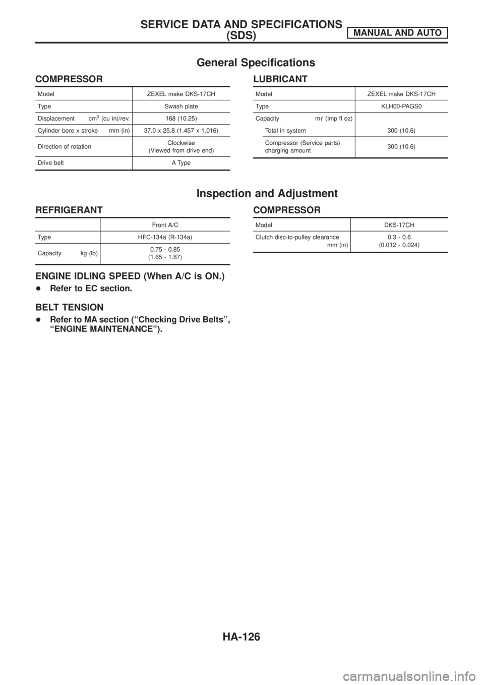
General Speci®cations
COMPRESSOR
Model ZEXEL make DKS-17CH
Type Swash plate
Displacement cm
3(cu in)/rev. 168 (10.25)
Cylinder bore x stroke mm (in) 37.0 x 25.8 (1.457 x 1.016)
Direction of rotationClockwise
(Viewed from drive end)
Drive belt A Type
LUBRICANT
Model ZEXEL make DKS-17CH
Type KLH00-PAGS0
Capacity m!(lmp ¯ oz)
Total in system 300 (10.6)
Compressor (Service parts)
charging amount300 (10.6)
Inspection and Adjustment
REFRIGERANT
Front A/C
Type HFC-134a (R-134a)
Capacity kg (lb)0.75 - 0.85
(1.65 - 1.87)
ENGINE IDLING SPEED (When A/C is ON.)
+Refer to EC section.
BELT TENSION
+Refer to MA section (``Checking Drive Belts'',
``ENGINE MAINTENANCE'').
COMPRESSOR
Model DKS-17CH
Clutch disc-to-pulley clearance
mm (in)0.3 - 0.6
(0.012 - 0.024)
SERVICE DATA AND SPECIFICATIONS
(SDS)MANUAL AND AUTO
HA-126
Page 949 of 1226
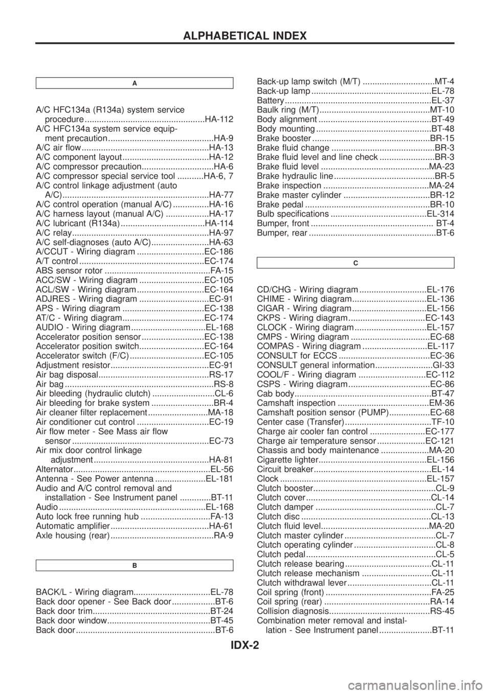
A
A/C HFC134a (R134a) system service
procedure ..................................................HA-112
A/C HFC134a system service equip-
ment precaution ............................................HA-9
A/C air ¯ow .....................................................HA-13
A/C component layout ....................................HA-12
A/C compressor precaution..............................HA-6
A/C compressor special service tool ...........HA-6, 7
A/C control linkage adjustment (auto
A/C).............................................................HA-77
A/C control operation (manual A/C) ...............HA-16
A/C harness layout (manual A/C) ..................HA-17
A/C lubricant (R134a) ...................................HA-114
A/C relay.........................................................HA-97
A/C self-diagnoses (auto A/C)........................HA-63
A/CCUT - Wiring diagram ............................EC-186
A/T control ....................................................EC-174
ABS sensor rotor ............................................FA-15
ACC/SW - Wiring diagram ...........................EC-105
ACL/SW - Wiring diagram ............................EC-164
ADJRES - Wiring diagram .............................EC-91
APS - Wiring diagram ..................................EC-138
AT/C - Wiring diagram..................................EC-174
AUDIO - Wiring diagram ...............................EL-168
Accelerator position sensor ..........................EC-138
Accelerator position switch...........................EC-164
Accelerator switch (F/C) ...............................EC-105
Adjustment resistor.........................................EC-91
Air bag disposal..............................................RS-17
Air bag ..............................................................RS-8
Air bleeding (hydraulic clutch) ..........................CL-6
Air bleeding for brake system ..........................BR-4
Air cleaner ®lter replacement .........................MA-18
Air conditioner cut control ..............................EC-19
Air ¯ow meter - See Mass air ¯ow
sensor .........................................................EC-73
Air mix door control linkage
adjustment ................................................HA-81
Alternator.........................................................EL-56
Antenna - See Power antenna .....................EL-181
Audio and A/C control removal and
installation - See Instrument panel .............BT-11
Audio .............................................................EL-168
Auto lock free running hub .............................FA-13
Automatic ampli®er .........................................HA-61
Axle housing (rear) ...........................................RA-9
B
BACK/L - Wiring diagram................................EL-78
Back door opener - See Back door ..................BT-6
Back door trim.................................................BT-24
Back door window...........................................BT-45
Back door ..........................................................BT-6Back-up lamp switch (M/T) ..............................MT-4
Back-up lamp ..................................................EL-78
Battery .............................................................EL-37
Baulk ring (M/T)..............................................MT-10
Body alignment ...............................................BT-49
Body mounting ................................................BT-48
Brake booster .................................................BR-15
Brake ¯uid change ...........................................BR-3
Brake ¯uid level and line check .......................BR-3
Brake ¯uid level .............................................MA-23
Brake hydraulic line ..........................................BR-5
Brake inspection ............................................MA-24
Brake master cylinder ....................................BR-12
Brake pedal ....................................................BR-10
Bulb speci®cations ........................................EL-314
Bumper, front ................................................... BT-4
Bumper, rear .....................................................BT-6
C
CD/CHG - Wiring diagram ............................EL-176
CHIME - Wiring diagram...............................EL-136
CIGAR - Wiring diagram ...............................EL-156
CKPS - Wiring diagram ................................EC-143
CLOCK - Wiring diagram ..............................EL-157
CMPS - Wiring diagram .................................EC-68
COMPAS - Wiring diagram ...........................EL-117
CONSULT for ECCS ......................................EC-36
CONSULT general information ........................GI-33
COOL/F - Wiring diagram ............................EC-112
CSPS - Wiring diagram ..................................EC-86
Cab body.........................................................BT-47
Camshaft inspection ......................................EM-36
Camshaft position sensor (PUMP).................EC-68
Center case (Transfer) ....................................TF-10
Charge air cooler fan control .......................EC-177
Charge air temperature sensor ....................EC-121
Chassis and body maintenance ....................MA-20
Cigarette lighter.............................................EL-156
Circuit breaker.................................................EL-14
Clock .............................................................EL-157
Clutch booster...................................................CL-9
Clutch cover ....................................................CL-14
Clutch damper ..................................................CL-7
Clutch disc ......................................................CL-13
Clutch ¯uid level.............................................MA-20
Clutch master cylinder ......................................CL-7
Clutch operating cylinder ..................................CL-8
Clutch pedal ......................................................CL-5
Clutch release bearing ....................................CL-11
Clutch release mechanism .............................CL-11
Clutch withdrawal lever ...................................CL-11
Coil spring (front) ............................................FA-25
Coil spring (rear) ............................................RA-14
Collision diagnosis..........................................RS-45
Combination meter removal and instal-
lation - See Instrument panel ......................BT-11
ALPHABETICAL INDEX
IDX-2
Page 952 of 1226
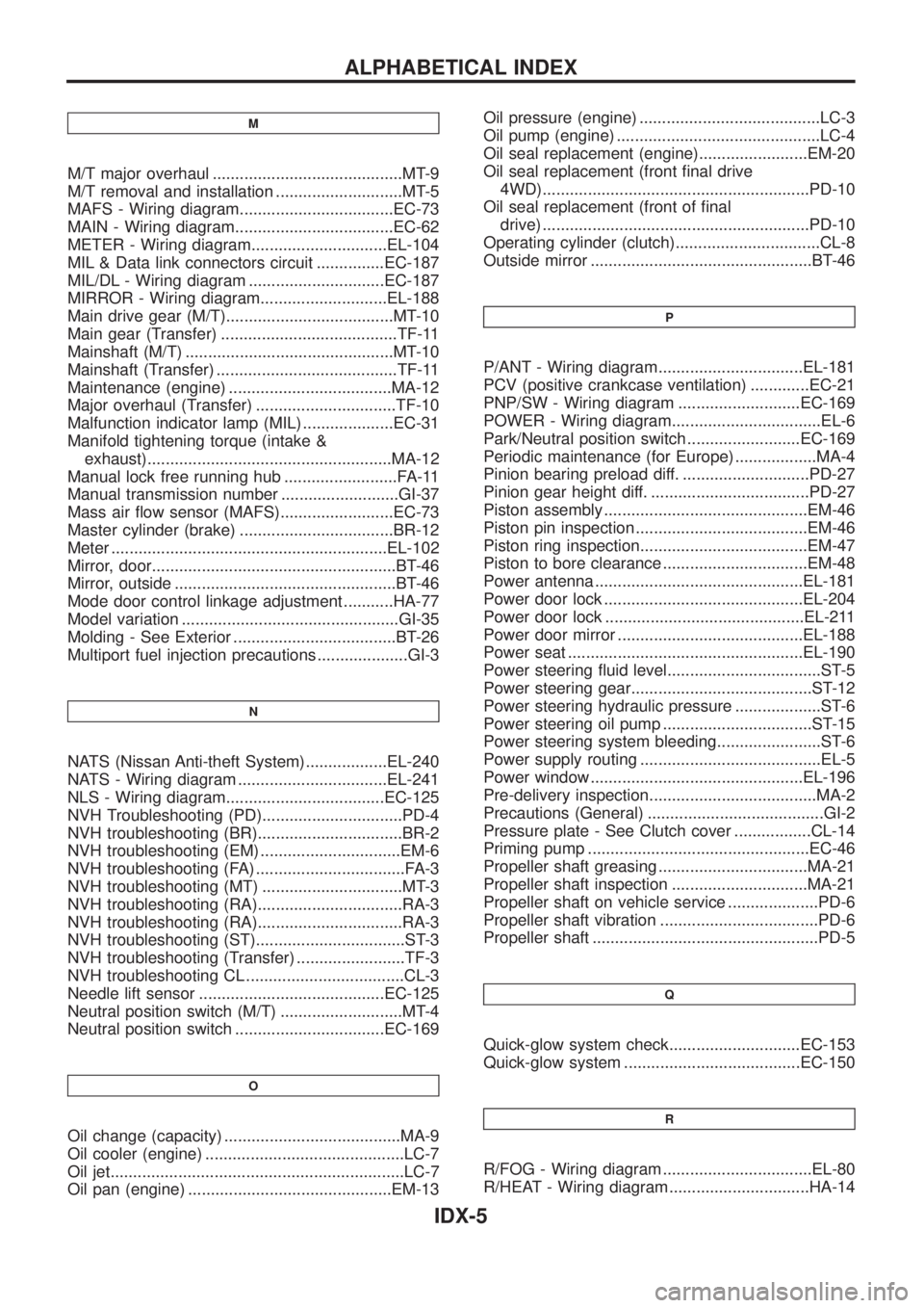
M
M/T major overhaul ..........................................MT-9
M/T removal and installation ............................MT-5
MAFS - Wiring diagram..................................EC-73
MAIN - Wiring diagram...................................EC-62
METER - Wiring diagram..............................EL-104
MIL & Data link connectors circuit ...............EC-187
MIL/DL - Wiring diagram ..............................EC-187
MIRROR - Wiring diagram............................EL-188
Main drive gear (M/T).....................................MT-10
Main gear (Transfer) .......................................TF-11
Mainshaft (M/T) ..............................................MT-10
Mainshaft (Transfer) ........................................TF-11
Maintenance (engine) ....................................MA-12
Major overhaul (Transfer) ...............................TF-10
Malfunction indicator lamp (MIL) ....................EC-31
Manifold tightening torque (intake &
exhaust)......................................................MA-12
Manual lock free running hub .........................FA-11
Manual transmission number ..........................GI-37
Mass air ¯ow sensor (MAFS).........................EC-73
Master cylinder (brake) ..................................BR-12
Meter .............................................................EL-102
Mirror, door......................................................BT-46
Mirror, outside .................................................BT-46
Mode door control linkage adjustment ...........HA-77
Model variation ................................................GI-35
Molding - See Exterior ....................................BT-26
Multiport fuel injection precautions ....................GI-3
N
NATS (Nissan Anti-theft System)..................EL-240
NATS - Wiring diagram .................................EL-241
NLS - Wiring diagram...................................EC-125
NVH Troubleshooting (PD)...............................PD-4
NVH troubleshooting (BR)................................BR-2
NVH troubleshooting (EM) ...............................EM-6
NVH troubleshooting (FA) .................................FA-3
NVH troubleshooting (MT) ...............................MT-3
NVH troubleshooting (RA)................................RA-3
NVH troubleshooting (RA)................................RA-3
NVH troubleshooting (ST).................................ST-3
NVH troubleshooting (Transfer) ........................TF-3
NVH troubleshooting CL ...................................CL-3
Needle lift sensor .........................................EC-125
Neutral position switch (M/T) ...........................MT-4
Neutral position switch .................................EC-169
O
Oil change (capacity) .......................................MA-9
Oil cooler (engine) ............................................LC-7
Oil jet.................................................................LC-7
Oil pan (engine) .............................................EM-13Oil pressure (engine) ........................................LC-3
Oil pump (engine) .............................................LC-4
Oil seal replacement (engine)........................EM-20
Oil seal replacement (front ®nal drive
4WD)...........................................................PD-10
Oil seal replacement (front of ®nal
drive) ...........................................................PD-10
Operating cylinder (clutch)................................CL-8
Outside mirror .................................................BT-46
P
P/ANT - Wiring diagram................................EL-181
PCV (positive crankcase ventilation) .............EC-21
PNP/SW - Wiring diagram ...........................EC-169
POWER - Wiring diagram.................................EL-6
Park/Neutral position switch .........................EC-169
Periodic maintenance (for Europe) ..................MA-4
Pinion bearing preload diff. ............................PD-27
Pinion gear height diff. ...................................PD-27
Piston assembly .............................................EM-46
Piston pin inspection ......................................EM-46
Piston ring inspection.....................................EM-47
Piston to bore clearance ................................EM-48
Power antenna ..............................................EL-181
Power door lock ............................................EL-204
Power door lock ............................................EL-211
Power door mirror .........................................EL-188
Power seat ....................................................EL-190
Power steering ¯uid level..................................ST-5
Power steering gear........................................ST-12
Power steering hydraulic pressure ...................ST-6
Power steering oil pump .................................ST-15
Power steering system bleeding.......................ST-6
Power supply routing ........................................EL-5
Power window ...............................................EL-196
Pre-delivery inspection.....................................MA-2
Precautions (General) .......................................GI-2
Pressure plate - See Clutch cover .................CL-14
Priming pump .................................................EC-46
Propeller shaft greasing .................................MA-21
Propeller shaft inspection ..............................MA-21
Propeller shaft on vehicle service ....................PD-6
Propeller shaft vibration ...................................PD-6
Propeller shaft ..................................................PD-5
Q
Quick-glow system check.............................EC-153
Quick-glow system .......................................EC-150
R
R/FOG - Wiring diagram .................................EL-80
R/HEAT - Wiring diagram ...............................HA-14
ALPHABETICAL INDEX
IDX-5
Page 953 of 1226
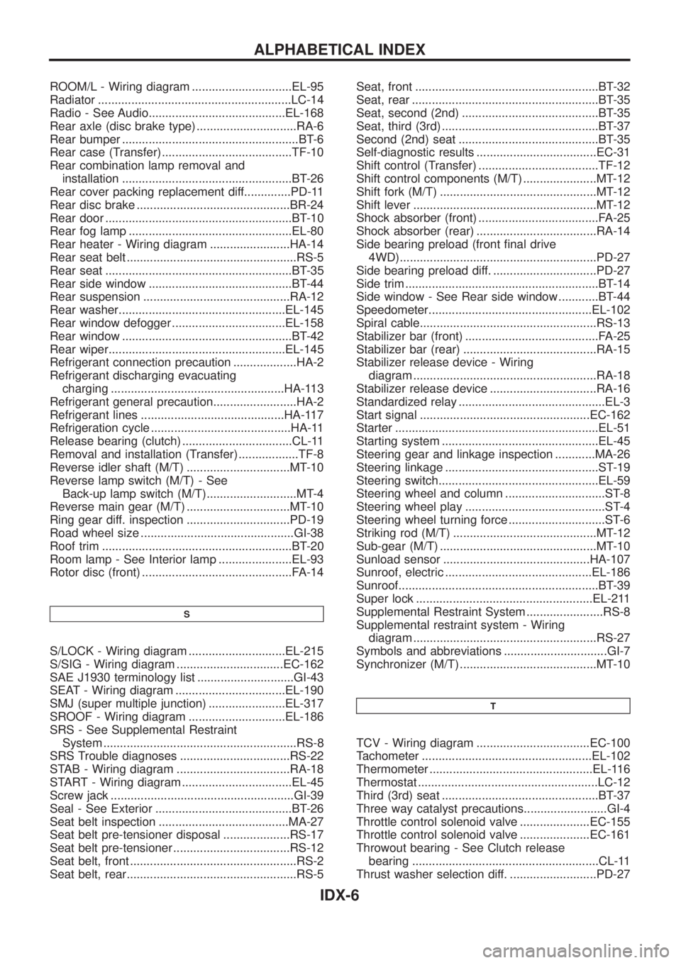
ROOM/L - Wiring diagram ..............................EL-95
Radiator ..........................................................LC-14
Radio - See Audio.........................................EL-168
Rear axle (disc brake type) ..............................RA-6
Rear bumper .....................................................BT-6
Rear case (Transfer) .......................................TF-10
Rear combination lamp removal and
installation ...................................................BT-26
Rear cover packing replacement diff..............PD-11
Rear disc brake ..............................................BR-24
Rear door ........................................................BT-10
Rear fog lamp .................................................EL-80
Rear heater - Wiring diagram ........................HA-14
Rear seat belt ...................................................RS-5
Rear seat ........................................................BT-35
Rear side window ...........................................BT-44
Rear suspension ............................................RA-12
Rear washer..................................................EL-145
Rear window defogger ..................................EL-158
Rear window ...................................................BT-42
Rear wiper.....................................................EL-145
Refrigerant connection precaution ...................HA-2
Refrigerant discharging evacuating
charging ....................................................HA-113
Refrigerant general precaution.........................HA-2
Refrigerant lines ...........................................HA-117
Refrigeration cycle ..........................................HA-11
Release bearing (clutch) .................................CL-11
Removal and installation (Transfer) ..................TF-8
Reverse idler shaft (M/T) ...............................MT-10
Reverse lamp switch (M/T) - See
Back-up lamp switch (M/T)...........................MT-4
Reverse main gear (M/T) ...............................MT-10
Ring gear diff. inspection ...............................PD-19
Road wheel size ..............................................GI-38
Roof trim .........................................................BT-20
Room lamp - See Interior lamp ......................EL-93
Rotor disc (front) .............................................FA-14
S
S/LOCK - Wiring diagram .............................EL-215
S/SIG - Wiring diagram ................................EC-162
SAE J1930 terminology list .............................GI-43
SEAT - Wiring diagram .................................EL-190
SMJ (super multiple junction) .......................EL-317
SROOF - Wiring diagram .............................EL-186
SRS - See Supplemental Restraint
System ..........................................................RS-8
SRS Trouble diagnoses .................................RS-22
STAB - Wiring diagram ..................................RA-18
START - Wiring diagram .................................EL-45
Screw jack .......................................................GI-39
Seal - See Exterior .........................................BT-26
Seat belt inspection .......................................MA-27
Seat belt pre-tensioner disposal ....................RS-17
Seat belt pre-tensioner ...................................RS-12
Seat belt, front ..................................................RS-2
Seat belt, rear...................................................RS-5Seat, front .......................................................BT-32
Seat, rear ........................................................BT-35
Seat, second (2nd) .........................................BT-35
Seat, third (3rd) ...............................................BT-37
Second (2nd) seat ..........................................BT-35
Self-diagnostic results ....................................EC-31
Shift control (Transfer) ....................................TF-12
Shift control components (M/T) ......................MT-12
Shift fork (M/T) ...............................................MT-12
Shift lever .......................................................MT-12
Shock absorber (front) ....................................FA-25
Shock absorber (rear) ....................................RA-14
Side bearing preload (front ®nal drive
4WD)...........................................................PD-27
Side bearing preload diff. ...............................PD-27
Side trim ..........................................................BT-14
Side window - See Rear side window ............BT-44
Speedometer.................................................EL-102
Spiral cable.....................................................RS-13
Stabilizer bar (front) ........................................FA-25
Stabilizer bar (rear) ........................................RA-15
Stabilizer release device - Wiring
diagram .......................................................RA-18
Stabilizer release device ................................RA-16
Standardized relay ............................................EL-3
Start signal ...................................................EC-162
Starter .............................................................EL-51
Starting system ...............................................EL-45
Steering gear and linkage inspection ............MA-26
Steering linkage ..............................................ST-19
Steering switch................................................EL-59
Steering wheel and column ..............................ST-8
Steering wheel play ..........................................ST-4
Steering wheel turning force .............................ST-6
Striking rod (M/T) ...........................................MT-12
Sub-gear (M/T) ...............................................MT-10
Sunload sensor ............................................HA-107
Sunroof, electric ............................................EL-186
Sunroof............................................................BT-39
Super lock .....................................................EL-211
Supplemental Restraint System .......................RS-8
Supplemental restraint system - Wiring
diagram .......................................................RS-27
Symbols and abbreviations ...............................GI-7
Synchronizer (M/T) .........................................MT-10
T
TCV - Wiring diagram ..................................EC-100
Tachometer ...................................................EL-102
Thermometer .................................................EL-116
Thermostat ......................................................LC-12
Third (3rd) seat ...............................................BT-37
Three way catalyst precautions.........................GI-4
Throttle control solenoid valve .....................EC-155
Throttle control solenoid valve .....................EC-161
Throwout bearing - See Clutch release
bearing ........................................................CL-11
Thrust washer selection diff. ..........................PD-27
ALPHABETICAL INDEX
IDX-6