Page 832 of 1226
Refrigeration Cycle
REFRIGERANT FLOW
The refrigerant ¯ow is in the standard pattern. Refrigerant ¯ows through the compressor, condenser, liquid
tank, evaporator and back to the compressor.
The refrigerant evaporation through the evaporator coil is controlled by an externally equalized expansion
valve, located inside the evaporator case.
FREEZE PROTECTION
The compressor cycles on and off to maintain the evaporator temperature within a speci®ed range. When the
evaporator coil temperature falls below a speci®ed point, the thermo control ampli®er interrupts the compres-
sor operation. When the evaporator coil temperature rises above the speci®cation, the thermo control ampli-
®er allows compressor operation.
REFRIGERANT SYSTEM PROTECTION
Dual-pressure switch
The dual-pressure switch is located on the liquid tank. If the system pressure rises or falls out of specifications,
the switch opens to interrupt compressor clutch operation.
RHA735G
DESCRIPTIONMANUAL AND AUTO
HA-11
Page 872 of 1226

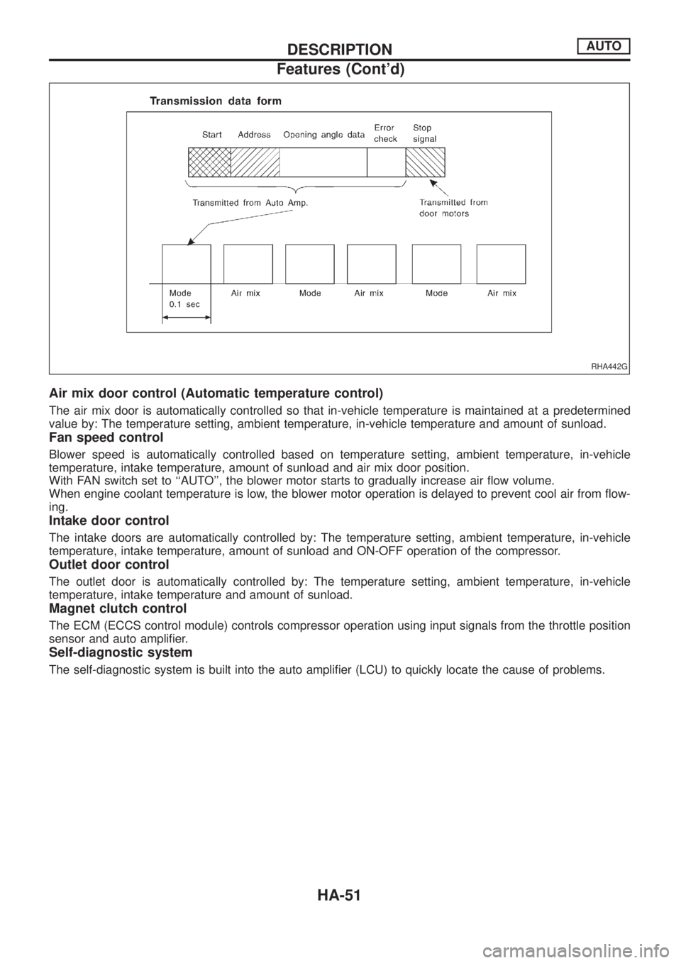
Air mix door control (Automatic temperature control)
The air mix door is automatically controlled so that in-vehicle temperature is maintained at a predetermined
value by: The temperature setting, ambient temperature, in-vehicle temperature and amount of sunload.
Fan speed control
Blower speed is automatically controlled based on temperature setting, ambient temperature, in-vehicle
temperature, intake temperature, amount of sunload and air mix door position.
With FAN switch set to ``AUTO'', the blower motor starts to gradually increase air ¯ow volume.
When engine coolant temperature is low, the blower motor operation is delayed to prevent cool air from ¯ow-
ing.
Intake door control
The intake doors are automatically controlled by: The temperature setting, ambient temperature, in-vehicle
temperature, intake temperature, amount of sunload and ON-OFF operation of the compressor.
Outlet door control
The outlet door is automatically controlled by: The temperature setting, ambient temperature, in-vehicle
temperature, intake temperature and amount of sunload.
Magnet clutch control
The ECM (ECCS control module) controls compressor operation using input signals from the throttle position
sensor and auto ampli®er.
Self-diagnostic system
The self-diagnostic system is built into the auto ampli®er (LCU) to quickly locate the cause of problems.
RHA442G
DESCRIPTIONAUTO
Features (Cont'd)
HA-51
Page 874 of 1226

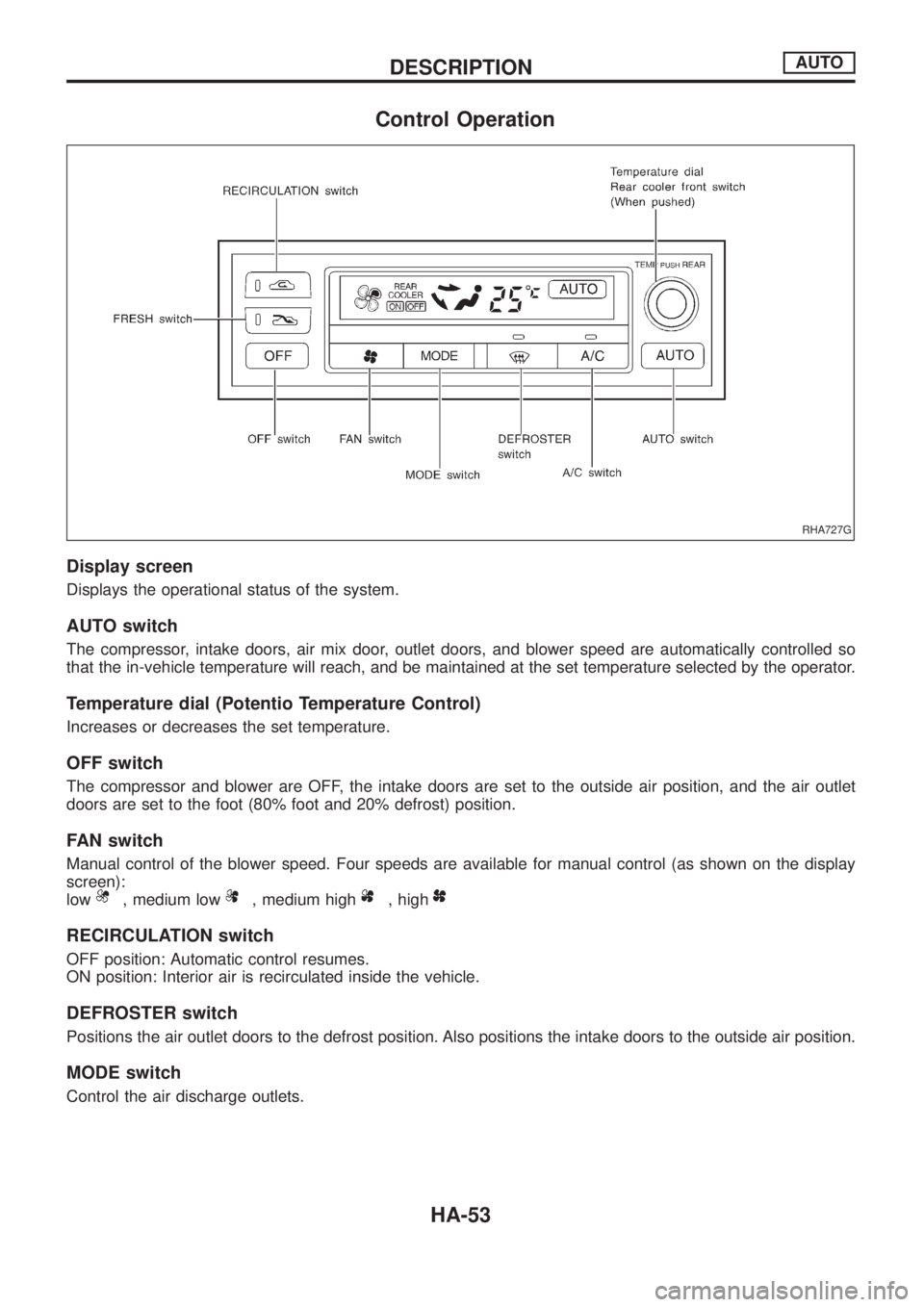
Control Operation
Display screen
Displays the operational status of the system.
AUTO switch
The compressor, intake doors, air mix door, outlet doors, and blower speed are automatically controlled so
that the in-vehicle temperature will reach, and be maintained at the set temperature selected by the operator.
Temperature dial (Potentio Temperature Control)
Increases or decreases the set temperature.
OFF switch
The compressor and blower are OFF, the intake doors are set to the outside air position, and the air outlet
doors are set to the foot (80% foot and 20% defrost) position.
FAN switch
Manual control of the blower speed. Four speeds are available for manual control (as shown on the display
screen):
low
, medium low, medium high, high
RECIRCULATION switch
OFF position: Automatic control resumes.
ON position: Interior air is recirculated inside the vehicle.
DEFROSTER switch
Positions the air outlet doors to the defrost position. Also positions the intake doors to the outside air position.
MODE switch
Control the air discharge outlets.
RHA727G
DESCRIPTIONAUTO
HA-53
Page 891 of 1226
Operational Check
The purpose of the operational check is to con®rm that the system
operates properly.
CONDITIONS
+Engine running and at normal operating temperature.
PROCEDURE
1. Check memory function
a. Set the temperature 25ÉC.
b. Press OFF switch.
c. Turn the ignition off.
d. Turn the ignition on.
e. Press the AUTO switch.
f. Con®rm that the set temperature remains at previous tempera-
ture.
g. Press OFF switch.
2. Check blower
a. Press fan switch one time.
Blower should operate on low speed.
The fan symbol should have one blade lit
.
b. Press fan switch one more time, and continue checking blower
speed and fan symbol until all speeds are checked.
c. Leave blower on MAX speed
.
3. Check discharge air
a. Press mode switch four times and DEF button.
RHA517G
RHA518G
RHA519G
RHA520G
TROUBLE DIAGNOSESAUTO
HA-70
Page 898 of 1226
Mode door control speci®cation
COMPONENT DESCRIPTION
The mode door motor is attached to the heater unit. It rotates so
that air is discharged from the outlet set by the auto ampli®er. Motor
rotation is conveyed to a link which activates the mode door.
CONTROL LINKAGE ADJUSTMENT
Mode door
1. Install mode door motor on heater unit and connect it to main
harness.
2. Set up code No.
in Self-diagnosis STEP 4. Refer to HA-67.
3. Move side link by hand and hold mode door in DEF mode.
4. Make sure mode door operates properly when changing from
code No.
toby pushing DEF switch.
VENT B/L B/L FOOT F/D DEF
RHA730G
RHA631G
TROUBLE DIAGNOSESAUTO
Mode Door Motor (Cont'd)
HA-77
Page 902 of 1226

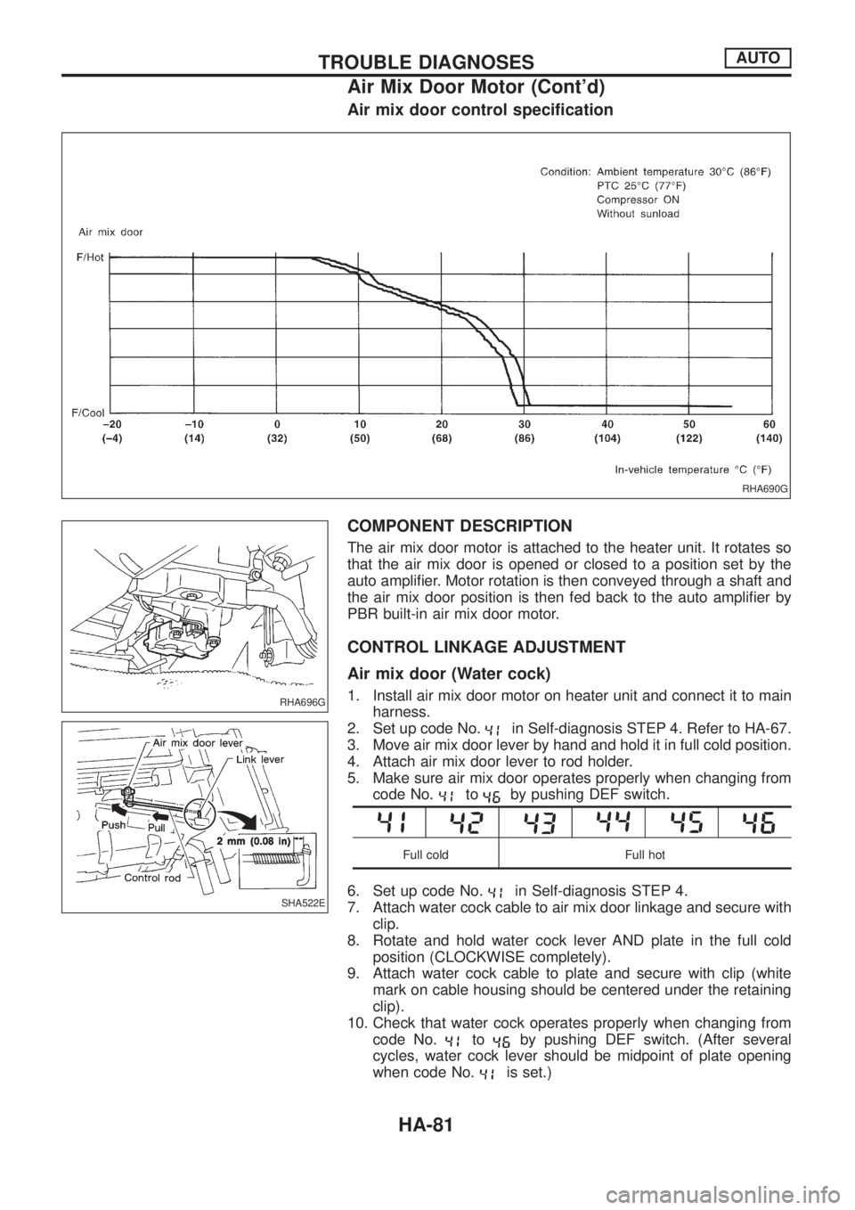
Air mix door control speci®cation
COMPONENT DESCRIPTION
The air mix door motor is attached to the heater unit. It rotates so
that the air mix door is opened or closed to a position set by the
auto ampli®er. Motor rotation is then conveyed through a shaft and
the air mix door position is then fed back to the auto ampli®er by
PBR built-in air mix door motor.
CONTROL LINKAGE ADJUSTMENT
Air mix door (Water cock)
1. Install air mix door motor on heater unit and connect it to main
harness.
2. Set up code No.
in Self-diagnosis STEP 4. Refer to HA-67.
3. Move air mix door lever by hand and hold it in full cold position.
4. Attach air mix door lever to rod holder.
5. Make sure air mix door operates properly when changing from
code No.
toby pushing DEF switch.
Full cold Full hot
6. Set up code No.in Self-diagnosis STEP 4.
7. Attach water cock cable to air mix door linkage and secure with
clip.
8. Rotate and hold water cock lever AND plate in the full cold
position (CLOCKWISE completely).
9. Attach water cock cable to plate and secure with clip (white
mark on cable housing should be centered under the retaining
clip).
10. Check that water cock operates properly when changing from
code No.
toby pushing DEF switch. (After several
cycles, water cock lever should be midpoint of plate opening
when code No.
is set.)
RHA690G
RHA696G
SHA522E
TROUBLE DIAGNOSESAUTO
Air Mix Door Motor (Cont'd)
HA-81
Page 905 of 1226
Intake door control speci®cation
COMPONENT DESCRIPTION
The intake door motor is attached to the intake unit. It rotates so
that air is drawn from inlets set by the auto ampli®er. Motor rota-
tion is conveyed to a lever which activates the intake door.
CONTROL LINKAGE ADJUSTMENT
Intake door
1. Install intake door motor on intake unit and connect it to main
harness.
2. Set up code No.
in Self-diagnosis STEP 4. Refer to HA-67.
3. Move intake door link by hand and hold it in REC position.
4. Attach intake door lever to rod holder.
5. Make sure intake door operates properly when changing from
code No.
toby pushing DEF switch.
REC 20% FRE FRE
RHA692G
RHA593F
TROUBLE DIAGNOSESAUTO
Intake Door Motor (Cont'd)
HA-84
Page 909 of 1226

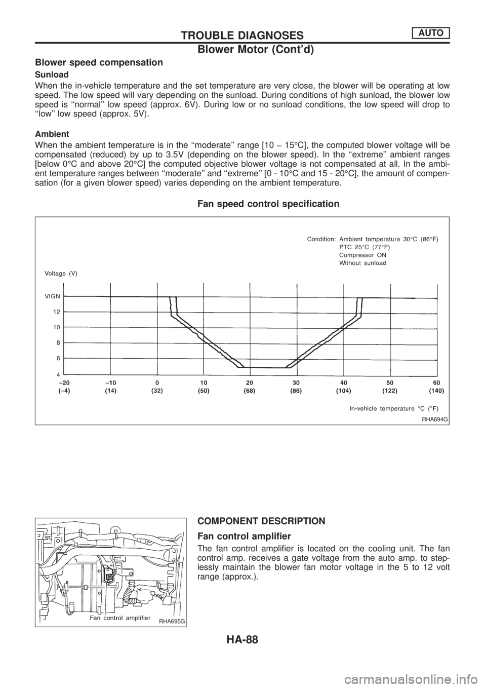
Blower speed compensation
Sunload
When the in-vehicle temperature and the set temperature are very close, the blower will be operating at low
speed. The low speed will vary depending on the sunload. During conditions of high sunload, the blower low
speed is ``normal'' low speed (approx. 6V). During low or no sunload conditions, the low speed will drop to
``low'' low speed (approx. 5V).
Ambient
When the ambient temperature is in the ``moderate'' range [10 þ 15ÉC], the computed blower voltage will be
compensated (reduced) by up to 3.5V (depending on the blower speed). In the ``extreme'' ambient ranges
[below 0ÉC and above 20ÉC] the computed objective blower voltage is not compensated at all. In the ambi-
ent temperature ranges between ``moderate'' and ``extreme'' [0 - 10ÉC and 15 - 20ÉC], the amount of compen-
sation (for a given blower speed) varies depending on the ambient temperature.
Fan speed control speci®cation
COMPONENT DESCRIPTION
Fan control ampli®er
The fan control ampli®er is located on the cooling unit. The fan
control amp. receives a gate voltage from the auto amp. to step-
lessly maintain the blower fan motor voltage in the 5 to 12 volt
range (approx.).
RHA694G
RHA695G
TROUBLE DIAGNOSESAUTO
Blower Motor (Cont'd)
HA-88