2006 MITSUBISHI COLT cvt
[x] Cancel search: cvtPage 4 of 364

GENERAL INFORMATION
ANTI-SKID BRAKE SYSTEM (ABS)35B-4
SYSTEM CONFIGURATION DIAGRAM
AC314168
Stop lamp switch
Front-right wheel speed sensor Rear-right wheel speed sensor
Rear-left wheel speed sensor Front-left wheel speed sensor
ABS-ECU power supply Engine-CVT-ECU
Front-right solenoid valve (out)
Front-right solenoid valve (in)
Front-left solenoid valve (out)
Front-left solenoid valve (in)
Rear-right solenoid valve (out)
Rear-right solenoid valve (in)
Rear-left solenoid valve (out)
Rear-left solenoid valve (in)
ABS-ECU
Hydraulic
unit Rear-right
wheel speed
sensor
Front right
wheel speed
sensor
Front-left
wheel speed
sensor Rear-left
wheel speed
sensor
Front-right wheel (FR)
Front-left wheel (FL) Rear-right wheel (RR)
Rear-left wheel (RL)
Stop lamp switch
AB
Brake warning lamp
ABS warning lamp
Diagnosis connector
NO TE: Broken lines show CAN-bus lin e.
Page 5 of 364

GENERAL INFORMATION
ANTI-SKID BRAKE SYSTEM (ABS)35B-5
ABS ELECTRICAL CIRCUIT DIAGRAM
AC314169
Engine-CVT-ECU
Front wheel speed
sensor Rear wheel speed
sensor
Motor power
supply
Solenoid valve
power supply
ABS-ECU
Motor power
supply
Solenoid valve
Hydraulic unit
Stop lamp
switch J/B
(Fuse)
No.42
15A No.40
7.5A
Fusible
link No.1
Ignition
switch (IG1) Fusible
link No.5 Fusible
link No.3
J/B
(Fuse)
No.33
15A Fusible
link No.6
J/C
(CAN2)
J/C
(CAN1) Diagnosis connector
Combination meter
(ABS warning lamp and
brake warning lamp)
AB
(rear, right)
(front, right)
(front, left)
(rear, left)
On
Off
Page 32 of 364

A/C-ECU
HEATER, AIR CONDITIONER AND VENTILATION55-8
A/C-ECU
M2551001200179
CONTROL SYSTEM
The manual and automatic A/Cs have the following
control functions.
ControlManual A/CAutomatic A/C
Automatic wind temperature change controlApplicableApplicable
Automatic outside/inside air selection controlApplicableApplicable
Idle-up controlApplicableApplicable
Cooling fun load controlApplicableApplicable
Cooling controlApplicableApplicable
Detection control for refrigerant leaksApplicableApplicable
MAX A/C controlNot applicableApplicable
Estimation control for compressor torqueApplicableApplicable
Defroster linked controlNot applicableApplicable
AUTOMATIC CHANGE CONTROL OF
BLOW WIND TEMPERATURE
(COMPRESSOR
ENERGY-CONSERVATION CONTROL)
Optimum ON/OFF control of the compressor is
achieved according to the outside/inside air mode,
air temperature (air temperature sensor), and insula
-
tion.
OUTSIDE/INSIDE AIR AUTO SWITCHING
CONTROL
When the A/C is turned on in high ambient tempera-
ture, the recirculation function is automatically acti-
vated to cool down the passenger compartment and
improve fuel consumption.
COOLING FUN LOAD CONTROL
Depending on the A/C load, the cooling fan cycle
time is controlled and the exterior noise in the inter
-
mediary stage is decreased. Also, the load of the
alternator is decreased to improve the fuel economy.
COOLING CONTROL
If air temperature is high, the CVT rotates at a high
speed to prevent deterioration in cooling perform
-
ance.
DETECTION CONTROL FOR
REFRIGERANT LEAKS
When it is judged from the air temperature (air tem-
perature sensor) and the refrigerant pressure (A/C
pressure sensor) that the refrigerant amount is the
specified value or less, or the refrigerant pressure is
abnormal, the compressor is forced to be cut off to
protect the A/C system.
MAX A/C CONTROL
When MAX COOL position is set, automatically the
mode is changed to the inside air mode before the
A/C is turned ON, thereby facilitating the operation
for obtaining maximum cooling performance.
ESTIMATION CONTROL FOR
COMPRESSOR TORQUE
Communication between the engine⋅CVT-ECU and
A/C-ECU is made to control the engine according to
the compressor torque for higher drivability and
reduction in fuel consumption.
FORCIBLE DEFROSTER CONTROL
When the defroster vents are selected, the A/C is
automatically turned ON. At this time, the out
-
side/inside air selection damper is operated to the
fresh-air position to defrost the windshield glass
quickly.
Page 33 of 364

A/C-ECU
HEATER, AIR CONDITIONER AND VENTILATION55-9
COMMUNICATION
The A/C receives the following kinds of signals
through CAN communication.
SignalTransmitter ECU
Engine coolant
temperature signalEngine-CVT-ECU
or Engine-ECU
NOTE: . For further details on CAN, refer to GROUP
54C, CAN
P.54C-2.
DIAGNOSTIC FUNCTION
Code No.Diagnostic itemService data display
contents when
diagnosis code is set
B1011Ambient temperature sensor system (short circuit)20°C
B1012Ambient temperature sensor system (open circuit)
B1021Air thermo sensor system (short circuit)−6°C
B1022Air thermo sensor system (open circuit)
B1082Automatic/manual types abnormal error−
U1073Bus off error−
U1100Engine-CVT-ECU time-out
U1101
U1102ABS-ECU time-out
U1106EPS-ECU time-out
U1109ETACS-ECU time-out
U1120Failure information on engine-CVT-ECU (related to engine)
U1206Flag invalid
Page 38 of 364

AIR INTAKE SYSTEM
INTAKE AND EXHAUST15-2
AIR INTAKE SYSTEM
AIR DUCT AND AIR CLEANER M2150004000504
CONSTRUCTION DIAGRAM
AC601193AB
Engine
air intake hose
Air cleaner intake duct
<4A9>
Engine
air intake hose
Air cleaner resonator
AC402138
Engine air intake hose
Air cleaner assembly
Air cleaner intake duct
AB
<4G1>
AC402138
•An air cleaner reson a tor ha s bee n adop ted to
improve eng
ine p e rformance and re duce air
in
t a ke no ise <4A9>.
•A front air int a ke system that actively su cks co ol-
ing air from th e front throug h the to p of th e radia-
tor ha s b een ad opted in ord e r to improve en gine
perf
o rman ce a nd redu ce air int a ke noise.
•For the air clea ner int a ke duct, a ve ntur i d u ct with
a diaphra
g m on it s p a th has been adopte d to su p
-
press rise in air resist ance and reduce air int a ke
noise.
•In considerat ion of ind u strial waste red u ction an d
global environment, re
cyc led mate rials made
from eating ut
ensils and th e scrap s ha ve be en
ado
pted for t he air clean er body and cover of t he
air cleaner a
sse mbly .
Page 43 of 364

EXHAUST SYSTEM
INTAKE AND EXHAUST15-7
EXHAUST PIPE AND MUFFLER <4A9>
M2150003000642
CONSTRUCTION DIAGRAM
AC601362AB
Centre exhaust pipeExhaust main muffler
Front exhaust pipeAnnular joint
Under floor catalytic converter
Exhaust pre-muffler
Insertion joint
AC601363AB
Centre exhaust pipeExhaust main muffler
Front exhaust pipeAnnular joint
Under floor catalytic converter
Exhaust pre-muffler
Insertion joint
Exhaust pipe consisting of th ree sep a ratio n system:
front exhaust pipe,
centre e x hau st pip e , and exhaust
main muf
f ler , has the fo llowing fea t ures:
•An exhaust pre-muff ler ha s be en in st alled to th e
ce
ntre exhaust pipe in order t o reduce exhaust
noise.
•An insertion joint has b een a dopted for the con-
nection between the centre exha ust p i pe and the
exhaust ma
in muf f ler to save the weight of the
exhaust system.
•The under floor cat a lytic con v erter has been
moved
clo s er to the e ngine side to impro v e
exhaust gas perfo
rmance.
•An annula r joint has been adopt ed for th e co n-
nection between the exhau st manifo ld an d the
fron
t exh aust pipe to redu ce th e exhaust pipe 's
vibration from the
engine side.
Page 97 of 364
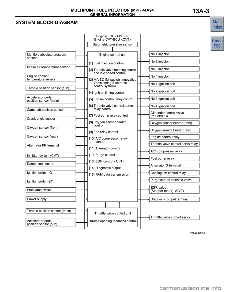
GENERAL INFORMATION
MULTIPOINT FUEL INJECTION (MPI) <4A9>13A-3
SYSTEM BLOCK DIAGRAM
AK600486
Barometric pressure sensorThrottle valve control servo
Manifold absolute pressure
sensor
Engine coolant
temperature sensor
No.1 injector
No.2 injector
No.3 injector
No.4 injector
No.1 Ignition coil
No.2 Ignition coil
No.3 Ignition coil
No.4 Ignition coil
Engine control relay
Throttle valve control servo relay
A/C compressor relay
Fuel pump relay
Alternator G terminal
Cooling fan control relay
Purge control solenoid valve
Diagnostic output terminal
Intake air temperature sensor
Accelerator pedal
position sensor (main) Throttle position sensor (sub)
Camshaft position sensor
Crank angle sensor
Oxygen sensor (front)
Oxygen sensor (rear)
Alternator FR terminal
Inhibitor switch
Detonation sensor
Ignition switch-IG
Ignition switch-ST
Stop lamp switch
Power supply
Accelerator pedel
position sensor (sub) Throttle position sensor (main)
Throttle valve control unitEngine control unit
Engine-ECU
Engine-CVT-ECU
Throttle opening feedback control Oxygen sensor heater (front)
Oxygen sensor heater (rear)
[1] Fuel injection control
[2] Throttle valve opening control
and idle speed control
[3] MIVEC (Mitsubishi Innovative
Valve timing Electronic
control system)
[4] Ignition timing control
[5] Engine control relay control
[6] Throttle valve control servo
relay control
[7] Fuel pump relay control
[8] Oxygen sensor heater
control
[9] Fan relay control
[10] A/C compressor relay
control
[11] Alternator control
[12] Purge control
[13] EGR control
[14] Diagnostic output
[15] RAM data transmission
Oil feeder control valve
(for MIVEC)
EGR valve
(Stepper motor)
AB
Page 99 of 364

GENERAL INFORMATION
MULTIPOINT FUEL INJECTION (MPI) <4A9>13A-5
AK403079
1 Oxygen sensor
(front)4 Intake air temperature
sensor
3 Manifold absolute
presssure sensor
2 Oxygen sensor (rear) 4 Throttle valve control
servo
10 Throttle position sensor
(main)
2 EGR valve
(stepper motor) 3 Purge control
solenoid valve
8 Engine coolant
temperature sensor
9 Detonation sensor
7 Crank angle sensor
6 Camshaft position sensor
5 Oil feeder control valve
1 Injector
AC
1 Oxygen sensor (front)
2 Oxygen sensor (rear)
3 Manifold absolute
presssure sensor
4 Intake air temperature
sensor
5 Throttle position
sensor (sub)
6 Camshaft position
sensor
7 Crank angle sensor
8 Engine coolant
temperature sensor
9 Detonation sensor
10 Throttle position
sensor (main) 1 Injector
2 EGR valve
(stepper motor)
3 Purge control
solenoid valve
4 Throttle valve control
servo
5 Oil feeder control
valve
Power supply
Ignition switch-IG
Ignition switch-ST
Accelerator pedal
position sensor
(main)
Accelerator pedal
position sensor
(sub)
Inhibitor switch
Alternator FR
terminal
Stop lamp switchEngine-
CVT-ECUEngine control relay
Fuel pump relay
A/C compressor relay
Throttle valve
control servo relay
Ignition coil
Cooling fan
control relay
Diagnosis output
Alternator G terminal
Oxygen sensor heater
(front)
Oxygen sensor heater
(rear)
Canister Air
inlet
Catalytic converter From fuel
pump
5 Throttle position sensor
(sub)
Barometric
pressure
sensor