2006 MITSUBISHI COLT diagram
[x] Cancel search: diagramPage 321 of 364

CONSTRUCTION DIAGRAM
ACTIVE STABILITY CONTROL SYSTEM (ASC)35C-11
C1371Yaw rate sensor signal
errorEnabledEnabledProhibitedProhibitedProhibitedProhibited
C1385Yaw rate sensor error
C1387Lateral G-sensor errorEnabledEnabledProhibitedProhibitedProhibitedProhibited
C1388Yaw rate sensor active
check errorEnabledEnabledProhibitedProhibitedProhibitedEnabled
C1394Steering wheel sensor
neutral point not learnedEnabledEnabledProhibitedProhibitedProhibitedProhibited
C1396Engine torque
intervention rejectionEnabledEnabledProhibitedProhibitedProhibitedProhibited
C1505Steering wheel sensor
malfunction (detection at
the ASC-ECU side)EnabledEnabledProhibitedProhibitedProhibitedProhibited
C1555Range exceeding of
steering wheel sensor
C1607Malfunction of ASC-ECUProhibitedProhibitedProhibitedProhibitedProhibitedProhibited
ASC-ECU malfunction
(CAN communication
circuit failure)EnabledEnabledProhibitedProhibitedProhibitedProhibited
C1621G and yaw rate sensor
improper installationEnabledEnabledProhibitedProhibitedProhibitedProhibited
C1860Abnormal rise of
ASC-ECU power supply
voltageProhibitedProhibitedProhibitedProhibitedProhibitedProhibited
C1861Abnormal drop of
ASC-ECU power supply
voltageProhibitedEnabledProhibitedProhibitedProhibitedProhibited
C1862Abnormal power supply
voltage of G and yaw rate
sensor (high voltage)EnabledEnabledProhibitedProhibitedProhibitedProhibited
C1863Abnormal power supply
voltage of G and yaw rate
sensor (low voltage)
U1073Bus-offEnabledEnabledProhibitedProhibitedProhibitedProhibited
U1100Engine-related CAN
time-out errorEnabledEnabledProhibitedProhibitedProhibitedProhibited
U1104Steering wheel sensor
CAN time-out errorEnabledEnabledProhibitedProhibitedProhibitedProhibited
U1105G and yaw rate sensor
CAN time-out errorEnabledEnabledProhibitedProhibitedProhibitedProhibited
U1406Accelerator pedal position
signal errorEnabledEnabledProhibitedProhibitedProhibitedProhibited
U1426Engine speed signal errorEnabledEnabledProhibitedProhibitedProhibitedProhibited
U1427Engine torque signal errorEnabledEnabledProhibitedProhibitedProhibitedProhibited
Diagnosis
code No.Item ABS EBD TCL ASC
Engine
controlBrake
controlEngine
controlBrake
control
Page 322 of 364

CONSTRUCTION DIAGRAM
ACTIVE STABILITY CONTROL SYSTEM (ASC)35C-12
Indicator lamp
U1428Engine's maximum torque
signal errorEnabledEnabledProhibitedProhibitedProhibitedProhibited
U1429Engine's minimum torque
signal errorEnabledEnabledProhibitedProhibitedProhibitedProhibited
U1430Engine torque request
signal errorEnabledEnabledProhibitedProhibitedProhibitedProhibited
Diagnosis
code No.Item ABS EBD TCL ASC
Engine
controlBrake
controlEngine
controlBrake
control
Diagnosis
code No.ItemBrake warning
lampABS warning lampActive stability
control system
(ASC) indicator
lamp ASC OFF indicator
lamp
C1200Wheel speed sensor
(FR) system (open or
short to earth or power
supply)Illuminates when
three wheels or
more are
abnormal.IlluminatesIlluminatesIlluminates
C1205Wheel speed sensor
(FL) system (open or
short to earth or power
supply)
C1210Wheel speed sensor
(RR) system (open or
short to earth or power
supply)
C1215Wheel speed sensor
(RL) system (open or
short to earth or power
supply)
C1201Wheel speed sensor
(FR) system (sensor
transmitting error)Illuminates when
three wheels or
more are
abnormal.IlluminatesIlluminatesIlluminates
C1206Wheel speed sensor
(FL) system (sensor
transmitting error)
C1211Wheel speed sensor
(RR) system (sensor
transmitting error)
C1216Wheel speed sensor
(RL) system (sensor
transmitting error)
C1222Wheel sensor system
(abnormal power
supply voltage)IlluminateIlluminateIlluminateIlluminate
C1225Wheel speed sensor
malfunctionIlluminatesIlluminatesIlluminatesIlluminates
Page 323 of 364

CONSTRUCTION DIAGRAM
ACTIVE STABILITY CONTROL SYSTEM (ASC)35C-13
C1226Control solenoid valve
(FR) pressure holding
systemIlluminatesIlluminatesIlluminatesIlluminates
C1231Control solenoid valve
(FR) decompressing
system
C1236Control solenoid valve
(FL) pressure holding
system
C1241Control solenoid valve
(FL) pressure reducing
system
C1246Control solenoid valve
(RR) pressure holding
system
C1251Control solenoid valve
(RR) pressure
reducing system
C1256Control solenoid valve
(RL) pressure holding
system
C1261Control solenoid valve
(RL) decompressing
system
C1266Pump motor rotation
malfunction OffIlluminatesIlluminatesIlluminates
C1273Pump motor drive
circuit malfunction
C1274Pump motor drive
circuit stuck on
C1276Valve relay systemIlluminatesIlluminatesIlluminatesIlluminates
C1278Valve relay stuck off
C1279Valve relay stuck on IlluminatesIlluminatesIlluminatesIlluminates
C1300Front-right cut valve
(Primary)IlluminatesIlluminatesIlluminatesIlluminates
C1305Front-right suction
valve (Primary)
C1310Front-left cut valve
(secondly)
C1315Front-left suction valve
(secondly)
C1340Abnormal stop lamp
switch signalOffIlluminatesIlluminatesIlluminates
C1345Low brake fluid levelIlluminatesOffOffOff
Diagnosis
code No.Item Brake warning
lampABS warning lamp Active stability
control system
(ASC) indicator
lamp ASC OFF indicator
lamp
Page 324 of 364

CONSTRUCTION DIAGRAM
ACTIVE STABILITY CONTROL SYSTEM (ASC)35C-14
C1364Brake fluid Pressure
sensor malfunctionOffIlluminatesIlluminatesIlluminates
C1366Lateral G sensor signal
malfunctionOffOffIlluminatesIlluminates
C1371Yaw rate sensor signal
malfunctionOffOffIlluminatesIlluminates
C1385Yaw rate sensor
malfunction
C1387Lateral G-sensor
malfunctionOffOffIlluminatesIlluminates
C1388Yaw rate sensor active
check error
C1394Steering wheel sensor
neutral point not
learnedOffOffIlluminatesIlluminates
C1396Active stability control
system control
temporarily disabled
(engine torque request
rejected)OffOffIlluminatesIlluminates
C1505Steering wheel sensor
abnormality (detected
at ABS/active stability
control
system-ECU-side)OffOffIlluminatesIlluminates
C1555Output error in steering
wheel sensor
C1607Defective active
stability control
system-ECUIlluminatesIlluminatesIlluminatesIlluminates
C1621G and yaw rate sensor
improper installationOffOffIlluminateIlluminate
C1860ABS/Active stability
control system-ECU
power supply voltage
malfunction (high
voltage) IlluminatesIlluminatesIlluminatesIlluminates
C1861ABS/Active stability
control system-ECU
power supply voltage
malfunction (low
voltage) IlluminatesIlluminatesIlluminatesIlluminates
C1862G and yaw rate sensor
power supply voltage
malfunction (high
voltage) OffOffIlluminatesIlluminates
Diagnosis
code No.Item Brake warning
lampABS warning lamp Active stability
control system
(ASC) indicator
lamp ASC OFF indicator
lamp
Page 325 of 364

CONSTRUCTION DIAGRAM
ACTIVE STABILITY CONTROL SYSTEM (ASC)35C-15
C1863G and yaw rate sensor
power supply voltage
malfunction (low
voltage) OffOffIlluminatesIlluminates
U1073Bus-offIlluminatesIlluminatesIlluminatesIlluminates
U1100Engine-related CAN
Timeout errorOffOffIlluminatesIlluminates
U1104Steering wheel sensor
CAN Timeout errorOffOffIlluminatesIlluminates
U1105G and yaw rate sensor
time-outOffOffIlluminatesIlluminates
U1406Failure information on
engine-A-M/T-ECU
(related to engine)OffOffIlluminatesIlluminates
U1426Failure information on
engine-A-M/T-ECU
(related to engine)OffOffIlluminatesIlluminates
U1427Failure information on
engine-A-M/T-ECU
(related to engine)
U1428Failure information on
engine-A-M/T-ECU
(related to engine)
U1429Failure information on
engine-A-M/T-ECU
(related to engine)
U1430Failure information on
engine-A-M/T-ECU
(related to engine)
Diagnosis
code No.Item Brake warning
lampABS warning lamp Active stability
control system
(ASC) indicator
lamp ASC OFF indicator
lamp
Page 326 of 364

CONSTRUCTION DIAGRAM
ACTIVE STABILITY CONTROL SYSTEM (ASC)35C-16
DIAGNOSIS CODE READING METHOD
There are 55 diagnosis items. The diagnosis code
can be checked using M.U.T.-III.
HOW TO ERASE DIAGNOSIS CODE
MEMORY
Diagnosis code can be erased using M.U.T.-III.
Data list output
The following items input to ASC-ECU can be read
using M.U.T.-III.
NOTE: For service data items, refer to Workshop
Manual.
Actuator test
By forcibly operating the actuator using M.U.T.-III,
the following operations can be performed.
•Forced ABS activation for each wheel
•Forced TCL (brake control) activation for each
wheel
•Forced TCL (engine control) activation
NOTE: .
•When ASC-ECU is disabled, the actuator test
cannot be performed.
•M.U.T.-III uses the ABS data list.
•For the actuator test specification, refer to Work-
shop Manual.
CALIBRATION
When the following operations are performed, the
steering wheel sensor needs to be calibrated using
the M.U.T.-III*.
•Front wheel alignment adjustment
•Steering wheel sensor replacement
NOTE: .
•M.U.T.-III uses the ABS data list.
•*: For calibration, refer to Workshop Manual.
Page 339 of 364

GENERAL INFORMATION
FUEL SUPPLY13C-3
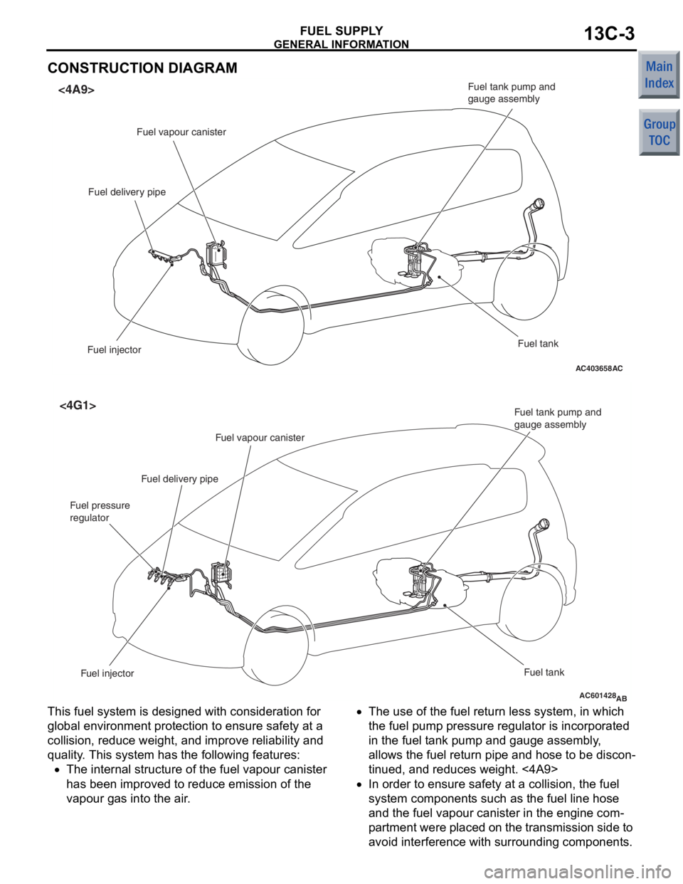
CONSTRUCTION DIAGRAM
AC403658AC
<4A9>
Fuel vapour canister
Fuel delivery pipe
Fuel injector Fuel tank
Fuel tank pump and
gauge assembly
AC601428AB
<4G1>
Fuel injector
Fuel tank
Fuel tank pump and
gauge assembly
Fuel vapour canister
Fuel delivery pipe
Fuel pressure
regulator
This fuel system is designed with considerat ion fo r
globa
l environ ment protection to ensure safety at a
collision,
reduce weigh t, and imp r ove re lia bility a nd
quality
. This system h a s th e following feature s :
•The intern al struct ure of t he fue l va pour canister
has bee
n improve d to re duce emission o f the
va
pour g a s into the air .
•The use of the fuel re turn less system, in wh ich
the
fuel pump pressure re gula t or is incorpora t ed
in
the fu el t ank pump and gauge assemb ly ,
allows t
he fue l return pipe and h o se to be d i scon
-
tinued, and red u ces weigh t. <4A9>
•In or der to ensu r e saf e ty a t a collision, the fuel
syst
em comp onent s such as the fue l line ho se
and
the fu el vapour canister in the engine com
-
pa rt men t were placed o n t he t r ansmissio n sid e to
avoid
interfe r ence with surroun ding componen t s .
Page 340 of 364

FUEL TANK
FUEL SUPPLY13C-4
•A resin coating is treated on the underfloor fuel
line pipes, improving reliability.
•A fuel tank pump with low power consumption
has been adopted to reduce the alternator load.
•A plastic tank pump and gauge assembly is used
to reduce weight.
•The fuel line tube and fuel line hose are made of
the material, which does not allow fuel vapour to
pass through it as much as possible, so that the
vapour gas emission to the air is reduced.
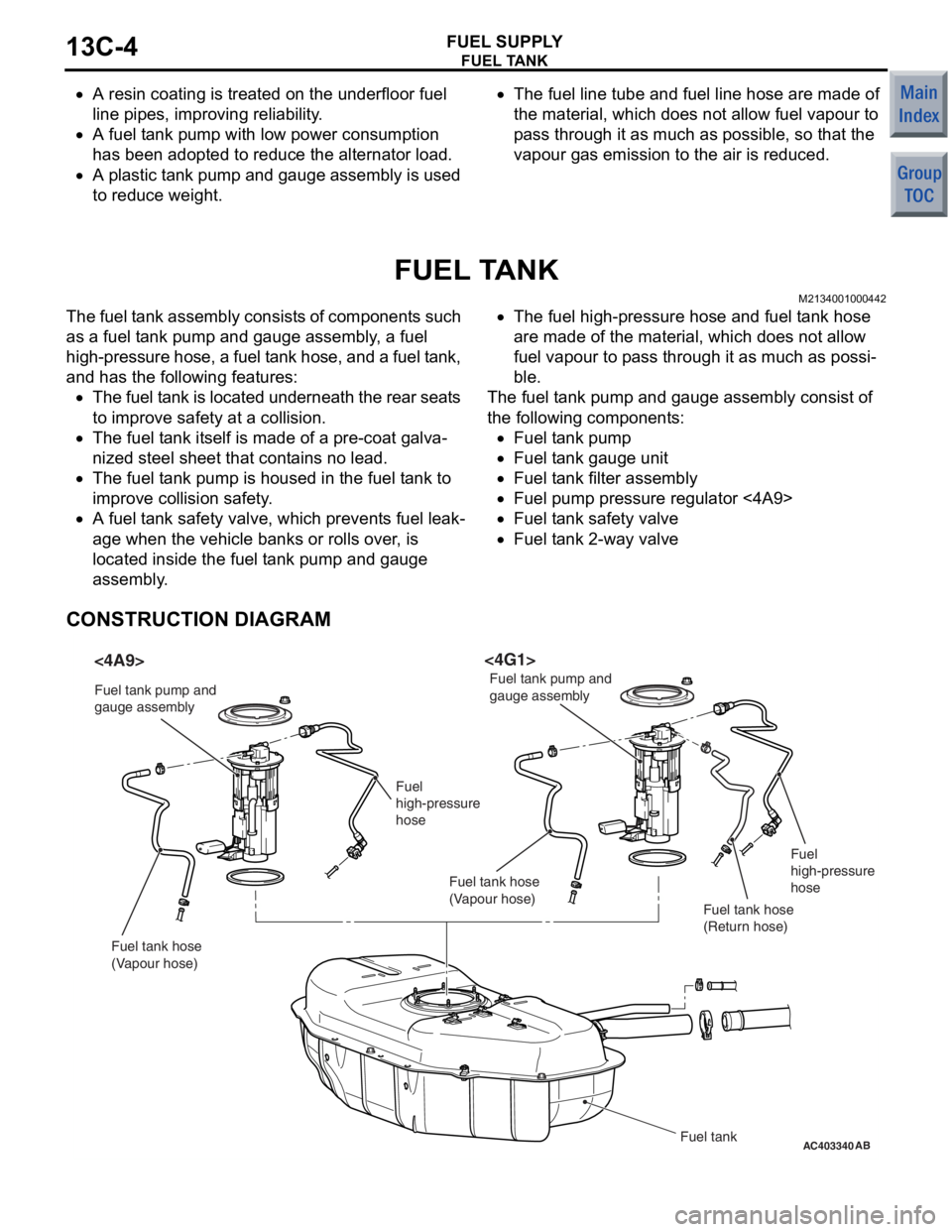
FUEL TANK
M2134001000442
The fuel tank assembly consists of components such
as a fuel tank pump and gauge assembly, a fuel
high-pressure hose, a fuel tank hose, and a fuel tank,
and has the following features:
•The fuel tank is located underneath the rear seats
to improve safety at a collision.
•The fuel tank itself is made of a pre-coat galva-
nized steel sheet that contains no lead.
•The fuel tank pump is housed in the fuel tank to
improve collision safety.
•A fuel tank safety valve, which prevents fuel leak-
age when the vehicle banks or rolls over, is
located inside the fuel tank pump and gauge
assembly.
•The fuel high-pressure hose and fuel tank hose
are made of the material, which does not allow
fuel vapour to pass through it as much as possi
-
ble.
The fuel tank pump and gauge assembly consist of
the following components:
•Fuel tank pump
•Fuel tank gauge unit
•Fuel tank filter assembly
•Fuel pump pressure regulator <4A9>
•Fuel tank safety valve
•Fuel tank 2-way valve
CONSTRUCTION DIAGRAM
AC403340AB
<4A9><4G1>
Fuel tank
Fuel tank pump and
gauge assembly
Fuel tank pump and
gauge assembly
Fuel
high-pressure
hose Fuel
high-pressure
hose
Fuel tank hose
(Vapour hose) Fuel tank hose
(Vapour hose)
Fuel tank hose
(Return hose)