Page 180 of 364
LIGHTING
CHASSIS ELECTRICAL54A-9
INTERIOR LAMP
The lens-push type map and room lamp is adopted
so that an excellent operationability can be achieved
allowing operation from driver and passenger seats.
Specifications
ItemSpecification
Map and room lamp W × units8 × 2
CONSTRUCTION DIAGRAM
AC601455
Map and room lamp
Map and room lamp
AB
Page 182 of 364
COMBINATION METER
CHASSIS ELECTRICAL54A-11
CONSTRUCTION DIAGRAM
AC601468AB
Water temperature gauge
Seat belt warning lamp
SpeedometerFog lamp indicator
Fuel gauge
Time setting buttonLiquid-crystal-display type
odometer and trip meter
(Clock function incorporated)
Tachometer
Tachometer
Speedometer
Water temperature gauge
Fuel gauge
Liquid-crystal-display type
odometer and trip meter
(Clock function incorporated) Time setting button
Seat belt warning lampFog lamp indicator
Tail lamp indicator
Reset button/
Rheostat (Meter illumination control)
Reset button
CVT only
Water temperature gauge
Seat belt warning lamp
SpeedometerFog lamp indicator
Fuel gauge
Time setting buttonLiquid-crystal-display type
odometer and trip meter
(Clock function incorporated)
TachometerReset button
Page 185 of 364
RADIO, CD PLAYER, SPEAKER, ANTENNA
CHASSIS ELECTRICAL54A-14
RADIO, CD PLAYER, SPEAKER, ANTENNA
M2540003200029
RADIO AND CD PLAYER
The electronically tuned AM/FM radio and CD player
incorporating 1 DIN-size power amplifier (25W
× 4) is
provided.
SPEAKER
Four speakers (front door: 13 cm, rear door: 13 cm)
are provided. The speaker is a dual cone full range
speaker.
ANTENNA
A roof antenna is provided.
CONSTRUCTION DIAGRAM
AC313795 AB
Roof antenna
Front speaker*
Rear speaker*
AC401638
NO
TE: The * ind i ca tes eq uippe d on the lef t and rig h t
side
s.
Page 204 of 364
TECHNICAL FEATURES
GENERAL00-19
ACTIVE SAFETY
M2000031000528
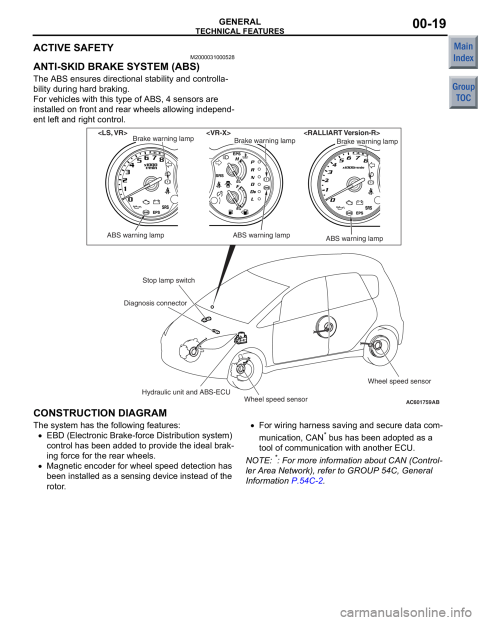
ANTI-SKID BRAKE SYSTEM (ABS)
The ABS ensures directional stability and controlla-
bility during hard braking.
For vehicles with this type of ABS, 4 sensors are
installed on front and rear wheels allowing independ
-
ent left and right control.
AC601759AB
ABS warning lamp
Brake warning lamp
ABS warning lamp
Brake warning lampBrake warning lamp
ABS warning lamp
Stop lamp switch
Hydraulic unit and ABS-ECUWheel speed sensor Wheel speed sensor
Diagnosis connector
CONSTRUCTION DIAGRAM
The syst
em has the following features:
•EBD (Electronic Bra ke-fo rce Distributio n system)
co ntrol has been added to provide t he ideal brak
-
in g force for th e rear wheels.
•Magnetic en coder for whee l speed de tection ha s
bee n inst alled as a se nsing device instead of the
rotor .
•For wiring h arness saving an d secure data com-
municatio n, CAN* b us h as be en ad opted a s a
too l of communication with another ECU.
NO TE: *: Fo r more information abo ut CAN (Control-
ler Area Netwo rk), re fer to GROUP 54C, Genera l
Information
P.54C-2.
Page 206 of 364
TECHNICAL FEATURES
GENERAL00-21
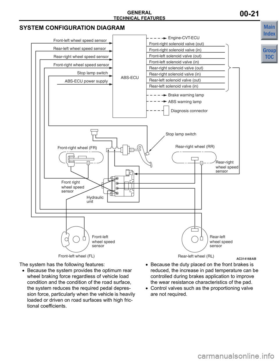
SYSTEM CONFIGURATION DIAGRAM
AC314168
Stop lamp switch
Front-right wheel speed sensor Rear-right wheel speed sensor
Rear-left wheel speed sensor Front-left wheel speed sensor
ABS-ECU power supply Engine-CVT-ECU
Front-right solenoid valve (out)
Front-right solenoid valve (in)
Front-left solenoid valve (out)
Front-left solenoid valve (in)
Rear-right solenoid valve (out)
Rear-right solenoid valve (in)
Rear-left solenoid valve (out)
Rear-left solenoid valve (in)
ABS-ECU
Hydraulic
unit Rear-right
wheel speed
sensor
Front right
wheel speed
sensor
Front-left
wheel speed
sensor Rear-left
wheel speed
sensor
Front-right wheel (FR)
Front-left wheel (FL) Rear-right wheel (RR)
Rear-left wheel (RL)
Stop lamp switch
AB
Brake warning lamp
ABS warning lamp
Diagnosis connector
The syst em has the following features:
•Because the system p rovides t he optimum rea r
wheel braking force regardless of vehicle load
co ndition a nd the condition of the road surface,
the system reduces the required pedal depre s
-
sion fo rce, particularly wh en th e veh icle is h eavily
lo aded o r driven on road surfaces with high fric
-
tional coef ficients.
•Because the duty place d on th e front brakes is
redu ced, th e increase in p ad tempe rature can be
controlled d uring brake s ap plication to impro ve
the we ar resist ance characteristics of the pad.
•Contro l valves such as the propo rtioning valve
are not required.
Page 208 of 364
TECHNICAL FEATURES
GENERAL00-23
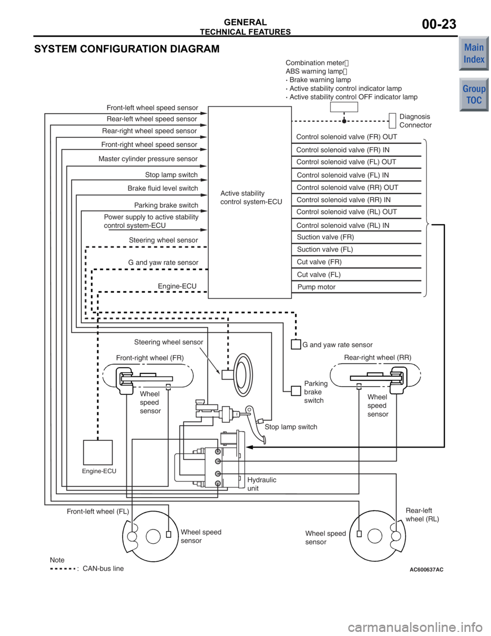
SYSTEM CONFIGURATION DIAGRAM
AC600637AC
Combination meter�
ABS warning lamp �
· Brake warning lamp
· Active stability control indicator lamp
· Active stability control OFF indicator lamp
Diagnosis
Connector
Control solenoid valve (FR) OUT
Control solenoid valve (FR) IN
Control solenoid valve (FL) OUT
Control solenoid valve (FL) IN
Control solenoid valve (RR) OUT
Control solenoid valve (RR) IN
Control solenoid valve (RL) OUT
Control solenoid valve (RL) IN Suction valve (FR)
Suction valve (FL)
Cut valve (FR)
Cut valve (FL) Pump motor
Active stability
control system-ECU
Front-left wheel speed sensor
Rear-left wheel speed sensor
Front-right wheel speed sensor Rear-right wheel speed sensor
Master cylinder pressure sensor Stop lamp switch
Parking brake switch
Brake fluid level switch
Power supply to active stability
control system-ECU Steering wheel sensor
G and yaw rate sensor
Engine-ECU
Steering wheel sensor
Front-right wheel (FR)
Wheel
speed
sensor
Engine-ECU
G and yaw rate sensor
Parking
brake
switch Rear-right wheel (RR)
Wheel
speed
sensor
Stop lamp switch
Hydraulic
unit Wheel speed
sensor Rear-left
wheel (RL)
Wheel speed
sensor
Front-left wheel (FL)
Note
: CAN-bus line
Page 211 of 364
TECHNICAL FEATURES
GENERAL00-26
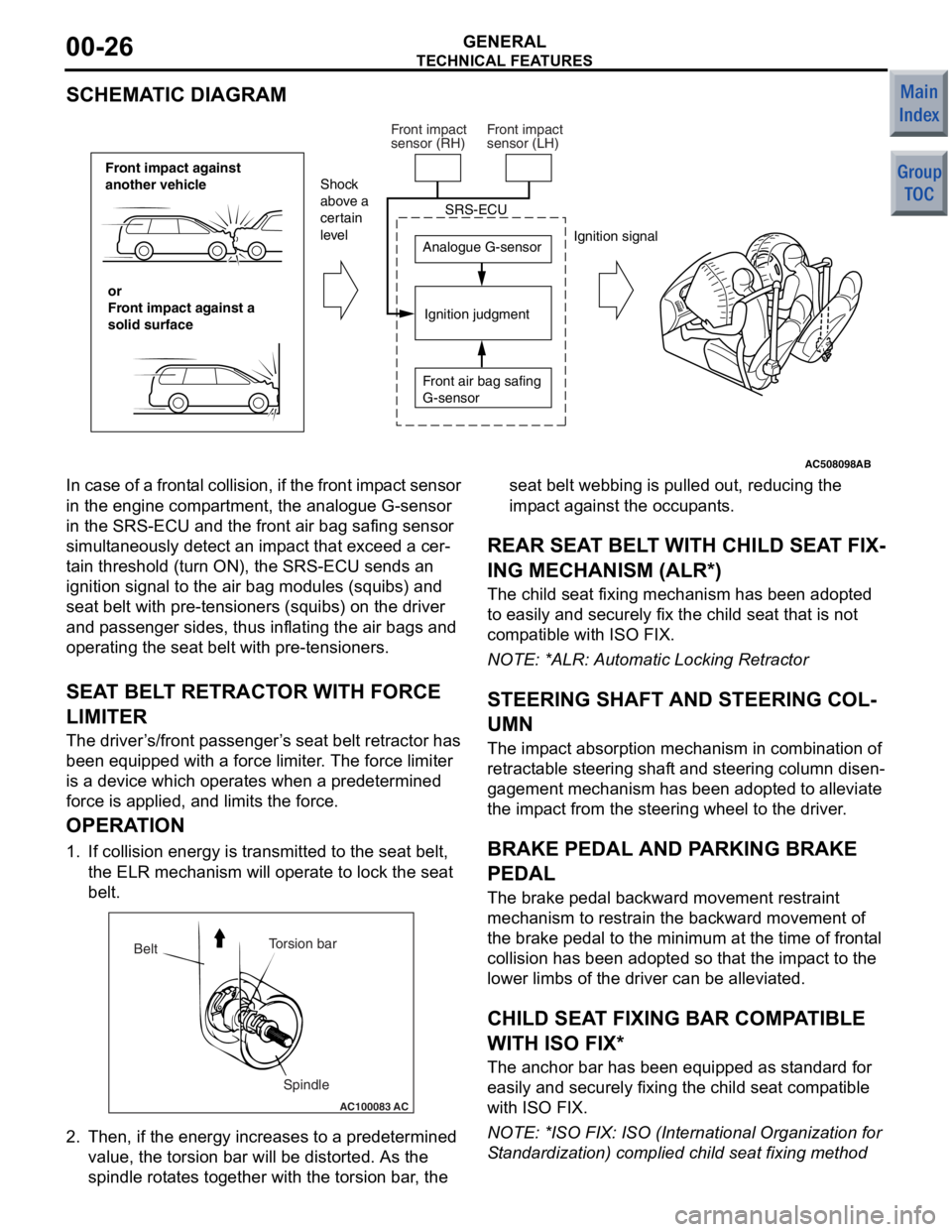
SCHEMATIC DIAGRAM
AC508098
Front impact against
another vehicleor
Front impact against a
solid surface Analogue G-sensor
Ignition judgment
Shock
above a
certain
level
Ignition signal
SRS-ECU
Front air bag safing
G-sensor
Front impact
sensor (RH)
Front impact
sensor (LH)
AB
In case of a
frontal collision, if the front imp act sensor
in the engine comp artment, the analogue G-sensor
in the SRS-ECU and t he front air bag safing sensor
simult aneously de tect an imp act th at excee d a cer
-
ta in threshold (turn ON), the SRS-ECU sen ds an
ignition signal to the air bag modules (squ ibs) and
seat belt with pre-te nsioners (squibs) on the driver
and p asseng er sides, thus inflating the air bag s and
operating the seat belt with pre -tensioner s.
SEAT BEL T RETRACT OR WITH FORCE
LIMITE R
The driver ’s /front p asseng er’s seat belt retractor has
been e quipped with a force limit er. The force limiter
is a device which operat es when a predetermined
force is applied, an d limits the for ce.
OPERA TION
1. If collision energy is transmit ted to the seat belt,
th e ELR mechanism will oper ate to lock the seat
be lt.
AC100083
Torsion bar
Spindle
Belt
AC
2.
Then, if the en ergy increase s to a prede termined
value , the to rsion bar will b e distorted . As th e
spind le rot ate s tog ether with the t orsion bar , the seat b
elt webb ing is p ulle d out, reducing th e
imp act against t he occupants.
REAR SEA T BELT WITH CHILD SEA T FIX-
ING MECHANISM (ALR*)
The child seat fixing mechanism h as b een ad opted
to easily and securely fix the child seat that is not
comp atible with ISO FIX.
NO TE: *ALR: Automatic Lockin g Retractor
STEERING SHAFT AND STEERING COL-
UMN
The impact ab sorption mech anism in combin ation of
retract able steerin g shaft and steering co lumn disen
-
gagement mecha nism has been ad opted t o alle viate
the imp act from th e steering wheel to the d rive r.
BRAKE PEDAL AND PA RKING BRAKE
PEDAL
The bra ke pe dal b ackward mo vement restraint
mechanism to restrain the backward movement of
the brake p edal to the minimum at the time o f f ront al
collision h as b een ad opted so that the impact to th e
lower limb s of the driver can be alleviated.
CHILD SEAT FIXING BAR COMP ATIBLE
WITH ISO FIX*
The an chor bar has been equipped a s st andard fo r
easily and secu rely fixing the child seat comp atible
with ISO FIX.
NO TE: *ISO F IX: ISO (In ternational Orga nization for
S tand ardizatio n) complied child se at fixing method
Page 219 of 364
GENERAL INFORMATION
POWER PLANT MOUNT32-2
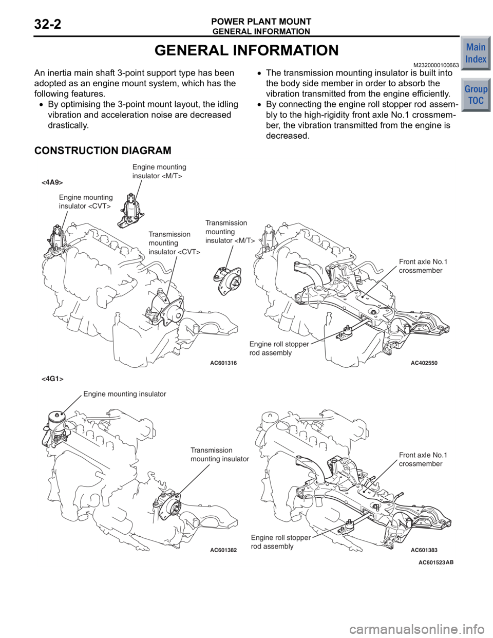
GENERAL INFORMATION
M2320000100663
An inertia main shaft 3-point support type has been
adopted as an engine mount system, which has the
following features.
•By optimising the 3-point mount layout, the idling
vibration and acceleration noise are decreased
drastically.
•The transmission mounting insulator is built into
the body side member in order to absorb the
vibration transmitted from the engine efficiently.
•By connecting the engine roll stopper rod assem-
bly to the high-rigidity front axle No.1 crossmem-
ber, the vibration transmitted from the engine is
decreased.
CONSTRUCTION DIAGRAM
AC601523
AC402550
AC601316
AC601382AC601383
<4A9>
<4G1>
AB
Engine mounting
insulator Engine mounting insulator Transmission
mounting
insulator
Transmission
mounting insulator Front axle No.1
crossmember
Front axle No.1
crossmember
Engine roll stopper
rod assembly
Engine mounting
insulator
Transmission
mounting
insulator
Engine roll stopper
rod assembly