Page 207 of 364
TECHNICAL FEATURES
GENERAL00-22
ACTIVE STABILITY CONTROL SYSYEM
(ASC)
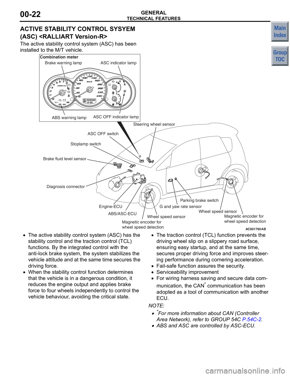
The active stability control system (ASC) has been
installed to the M/T vehicle.
AC601760AB
ABS warning lamp
Diagnosis connector Stoplamp switch
Steering wheel sensor
Wheel speed sensor Wheel speed sensor
G and yaw rate sensorParking brake switch
ASC OFF switch ASC indicator lamp
ASC OFF indicator lamp
Brake warning lamp
Combination meter
Brake fluid level sensor ABS/ASC-ECU
Engine-ECU
Magnetic encoder for
wheel speed detection Magnetic encoder for
wheel speed detection
•The
active st ability control syst em (ASC) has the
st ab ility control and t he traction control (TCL)
fun ctio ns. By the integra ted control with th e
ant i-lock b rake system, the system stabilizes th e
ve hicle attitu de and at the same time secures the
drivin g force.
•When the st ability control fun ction dete rmin es
tha t the vehicle is in a dangerou s condition, it
redu ces the e ngine outpu t and a pplies b rake
force to f our wheels indepe ndently to control th e
ve hicle be haviour, avoiding the critical state.
•The tract ion control (TCL) fun ction prevent s the
drivin g wheel slip on a slippery road sur face,
ensurin g easy st artup, an d at the same time,
secure s proper drivin g force and improves ste er
-
in g perfo rmance du ring cornering acce leration.
•Fail-safe functio n assures the security.
•Serviceability imp rovement
•For wiring h arness saving an d secure data com-
municatio n, the CAN* co mmunicatio n has been
ado pted a s a t ool o f commun ication with ano ther
ECU.
NO TE: .
•*For more informatio n about CAN (Con troller
Area Net wor k), refe r to GROUP 54C
P.54C-2.
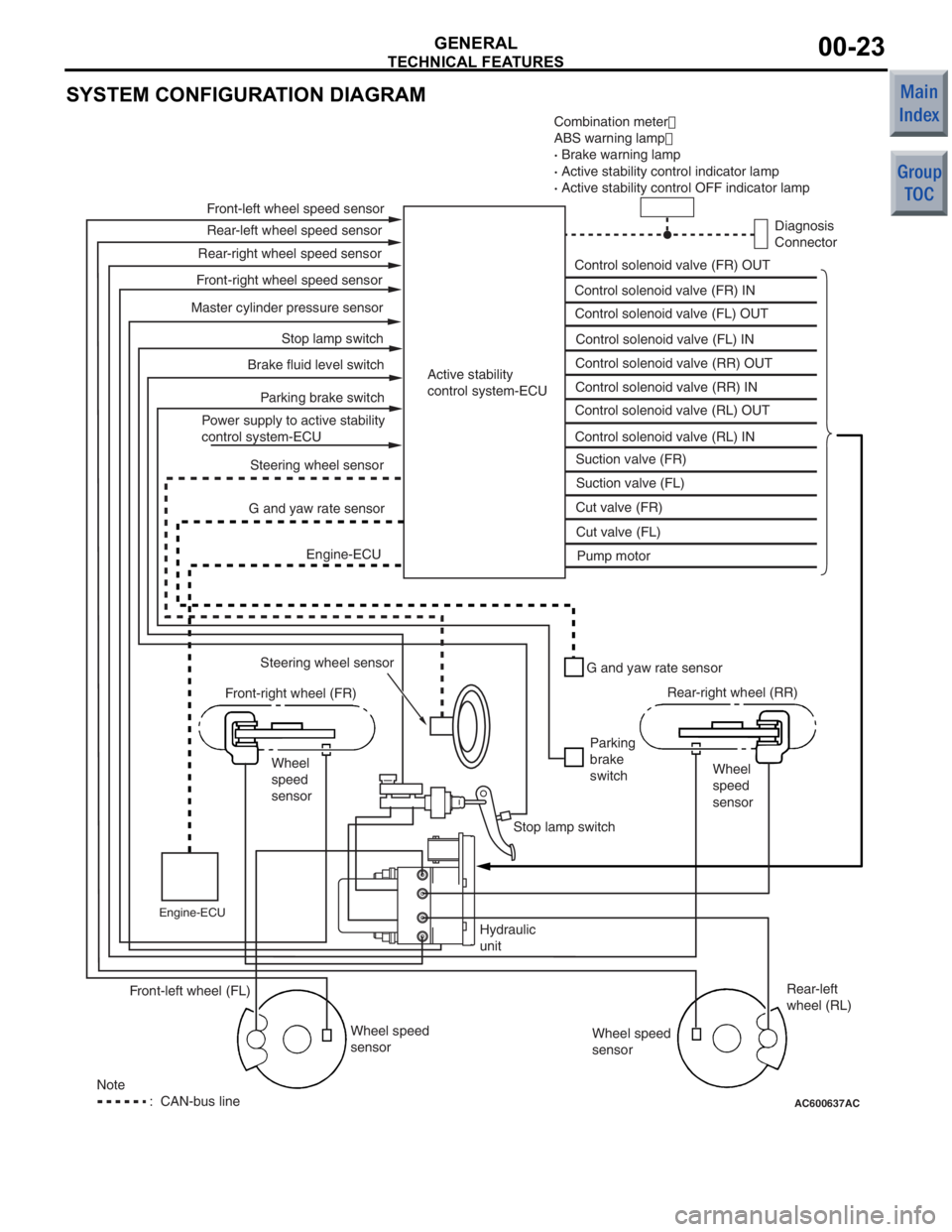
•ABS and ASC are controlled by ASC-ECU.
Page 208 of 364
TECHNICAL FEATURES
GENERAL00-23
SYSTEM CONFIGURATION DIAGRAM
AC600637AC
Combination meter�
ABS warning lamp �
· Brake warning lamp
· Active stability control indicator lamp
· Active stability control OFF indicator lamp
Diagnosis
Connector
Control solenoid valve (FR) OUT
Control solenoid valve (FR) IN
Control solenoid valve (FL) OUT
Control solenoid valve (FL) IN
Control solenoid valve (RR) OUT
Control solenoid valve (RR) IN
Control solenoid valve (RL) OUT
Control solenoid valve (RL) IN Suction valve (FR)
Suction valve (FL)
Cut valve (FR)
Cut valve (FL) Pump motor
Active stability
control system-ECU
Front-left wheel speed sensor
Rear-left wheel speed sensor
Front-right wheel speed sensor Rear-right wheel speed sensor
Master cylinder pressure sensor Stop lamp switch
Parking brake switch
Brake fluid level switch
Power supply to active stability
control system-ECU Steering wheel sensor
G and yaw rate sensor
Engine-ECU
Steering wheel sensor
Front-right wheel (FR)
Wheel
speed
sensor
Engine-ECU
G and yaw rate sensor
Parking
brake
switch Rear-right wheel (RR)
Wheel
speed
sensor
Stop lamp switch
Hydraulic
unit Wheel speed
sensor Rear-left
wheel (RL)
Wheel speed
sensor
Front-left wheel (FL)
Note
: CAN-bus line
Page 211 of 364
TECHNICAL FEATURES
GENERAL00-26
SCHEMATIC DIAGRAM
AC508098
Front impact against
another vehicleor
Front impact against a
solid surface Analogue G-sensor
Ignition judgment
Shock
above a
certain
level
Ignition signal
SRS-ECU
Front air bag safing
G-sensor
Front impact
sensor (RH)
Front impact
sensor (LH)
AB
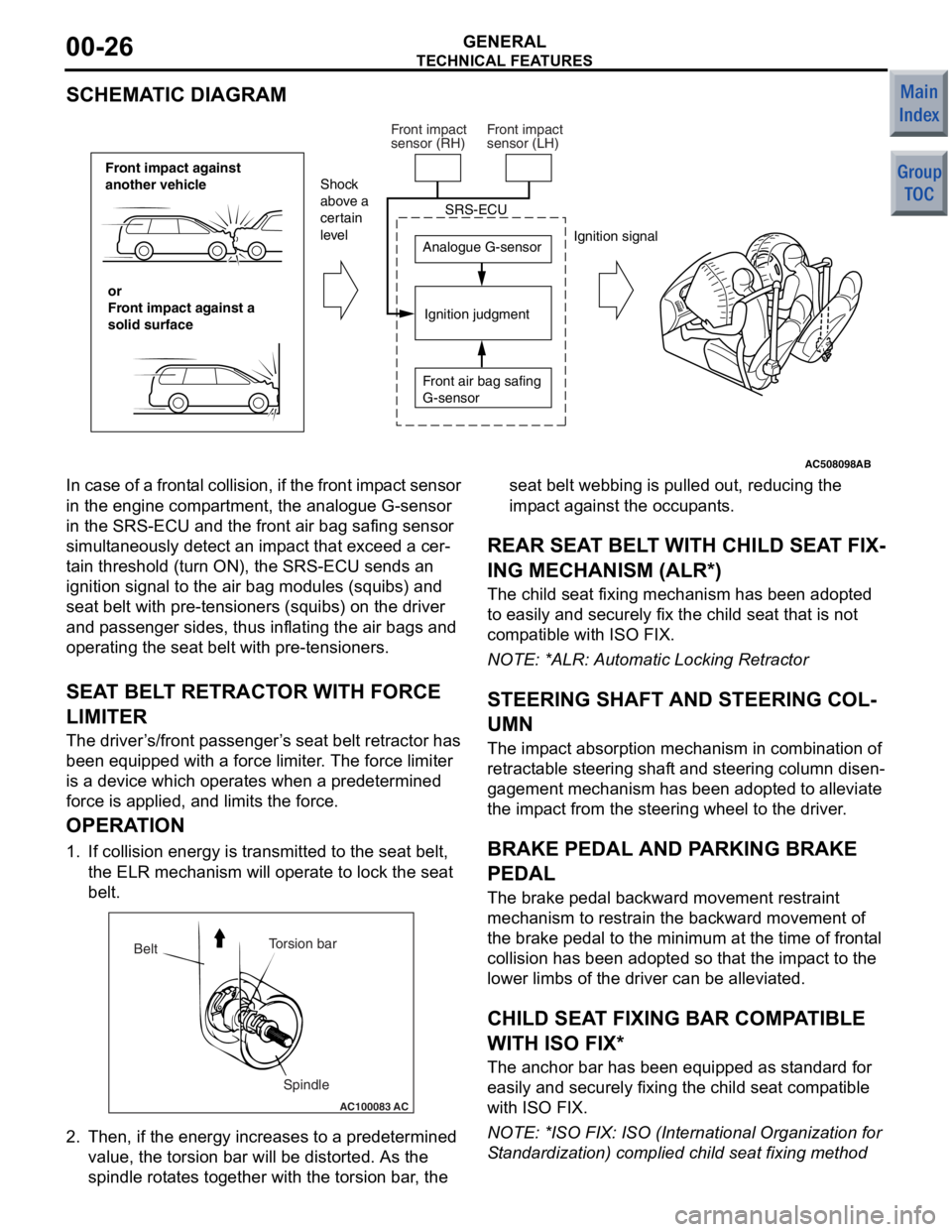
In case of a
frontal collision, if the front imp act sensor
in the engine comp artment, the analogue G-sensor
in the SRS-ECU and t he front air bag safing sensor
simult aneously de tect an imp act th at excee d a cer
-
ta in threshold (turn ON), the SRS-ECU sen ds an
ignition signal to the air bag modules (squ ibs) and
seat belt with pre-te nsioners (squibs) on the driver
and p asseng er sides, thus inflating the air bag s and
operating the seat belt with pre -tensioner s.
SEAT BEL T RETRACT OR WITH FORCE
LIMITE R
The driver ’s /front p asseng er’s seat belt retractor has
been e quipped with a force limit er. The force limiter
is a device which operat es when a predetermined
force is applied, an d limits the for ce.
OPERA TION
1. If collision energy is transmit ted to the seat belt,
th e ELR mechanism will oper ate to lock the seat
be lt.
AC100083
Torsion bar
Spindle
Belt
AC
2.
Then, if the en ergy increase s to a prede termined
value , the to rsion bar will b e distorted . As th e
spind le rot ate s tog ether with the t orsion bar , the seat b
elt webb ing is p ulle d out, reducing th e
imp act against t he occupants.
REAR SEA T BELT WITH CHILD SEA T FIX-
ING MECHANISM (ALR*)
The child seat fixing mechanism h as b een ad opted
to easily and securely fix the child seat that is not
comp atible with ISO FIX.
NO TE: *ALR: Automatic Lockin g Retractor
STEERING SHAFT AND STEERING COL-
UMN
The impact ab sorption mech anism in combin ation of
retract able steerin g shaft and steering co lumn disen
-
gagement mecha nism has been ad opted t o alle viate
the imp act from th e steering wheel to the d rive r.
BRAKE PEDAL AND PA RKING BRAKE
PEDAL
The bra ke pe dal b ackward mo vement restraint
mechanism to restrain the backward movement of
the brake p edal to the minimum at the time o f f ront al
collision h as b een ad opted so that the impact to th e
lower limb s of the driver can be alleviated.
CHILD SEAT FIXING BAR COMP ATIBLE
WITH ISO FIX*
The an chor bar has been equipped a s st andard fo r
easily and secu rely fixing the child seat comp atible
with ISO FIX.
NO TE: *ISO F IX: ISO (In ternational Orga nization for
S tand ardizatio n) complied child se at fixing method
Page 214 of 364

TECHNICAL FEATURES
GENERAL00-29
IMPROVED SERVICEABILITY
•Employment of an automatic hydraulic timing belt
tensioner offers timing belt reliability, reduced
operating noise, and better serviceability. <4G1>
•Wiring harness section of the crank angle sensor
has been moulded integrally with the timing belt
cover, improving serviceability and reliability.
<4G1>
•Due to the adoption of the timing chain and the
timing chain tensioner, maintenance-free and reli
-
ability have been improved. <4A9>
•Since adoption of unvolatile memory (EEPROM*)
helps the learned value not to be initialised when
the battery terminal or connector of the control
unit is disconnected, maintainability can be
improved.
NOTE: *EEPROM: Electrical Erasable Programma-
ble ROM (information to be memorised can be
electronically written into and erased from ROM)
•Since the adoption of electric power steering
makes hydraulic pipes and oil pumps unneces
-
sary, maintainability can be improved.
•Employment of operative A/C piping layout and
refrigerant leak detection system enhances serv
-
iceability.
Page 236 of 364
GENERAL INFORMATION
POWER STEERING37-3
CONSTRUCTION DIAGRAM
AC405883AB
Steering wheel
Steering column assembly
Selector lever assembly
Electric power
steering-ECU
Motor
Torque sensor
Tie-rod end Steering gearDash panel cover
Page 237 of 364
AC405884AB
Steering wheel
Steering column assembly
Electric power
steering-ECU
Motor
Torque sensor
Tie-rod end
Yoke bearing
Steering gearDash panel cover
GENER
A L IN FORMA T ION
POWER ST E E RING37-4
Page 240 of 364
ELECTRICAL POWER STEERING
POWER STEERING37-7
ELECTRICAL POWER STEERING
GENERAL INFORMATIONM2370000100862
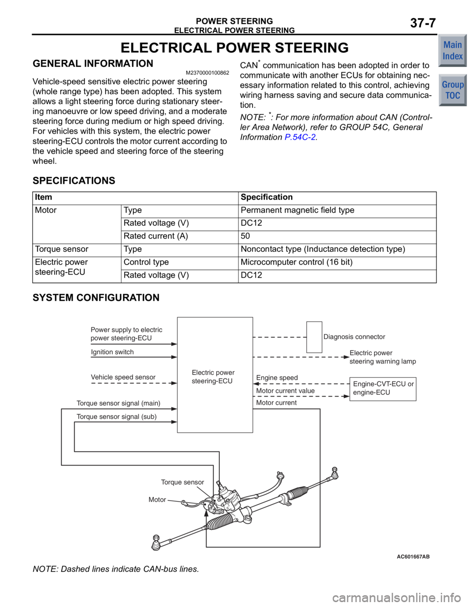
Vehicle-speed sensitive electric power steering
(whole range type) has been adopted. This system
allows a light steering force during stationary steer
-
ing manoeuvre or low speed driving, and a moderate
steering force during medium or high speed driving.
For vehicles with this system, the electric power
steering-ECU controls the motor current according to
the vehicle speed and steering force of the steering
wheel.
CAN* communication has been adopted in order to
communicate with another ECUs for obtaining nec
-
essary information related to this control, achieving
wiring harness saving and secure data communica
-
tion.
NOTE: *: For more information about CAN (Control-
ler Area Network), refer to GROUP 54C, General
Information
P.54C-2.
SPECIFICATIONS
ItemSpecification
MotorTy p ePermanent magnetic field type
Rated voltage (V)DC12
Rated current (A)50
Torque sensorTy p eNoncontact type (Inductance detection type)
Electric power
steering-ECUControl typeMicrocomputer control (16 bit)
Rated voltage (V)DC12
SYSTEM CONFIGURATION
AC601667AB
Electric power
steering-ECU
Ignition switch
Power supply to electric
power steering-ECU
Vehicle speed sensor
Motor Motor current value Engine speed
Torque sensor signal (main) Electric power
steering warning lamp
Diagnosis connector
Motor current
Torque sensor
Torque sensor signal (sub) Engine-CVT-ECU or
engine-ECU
NO
TE: Dash ed lines indicat e CAN-bu s lines.
Page 241 of 364
ELECTRICAL POWER STEERING
POWER STEERING37-8
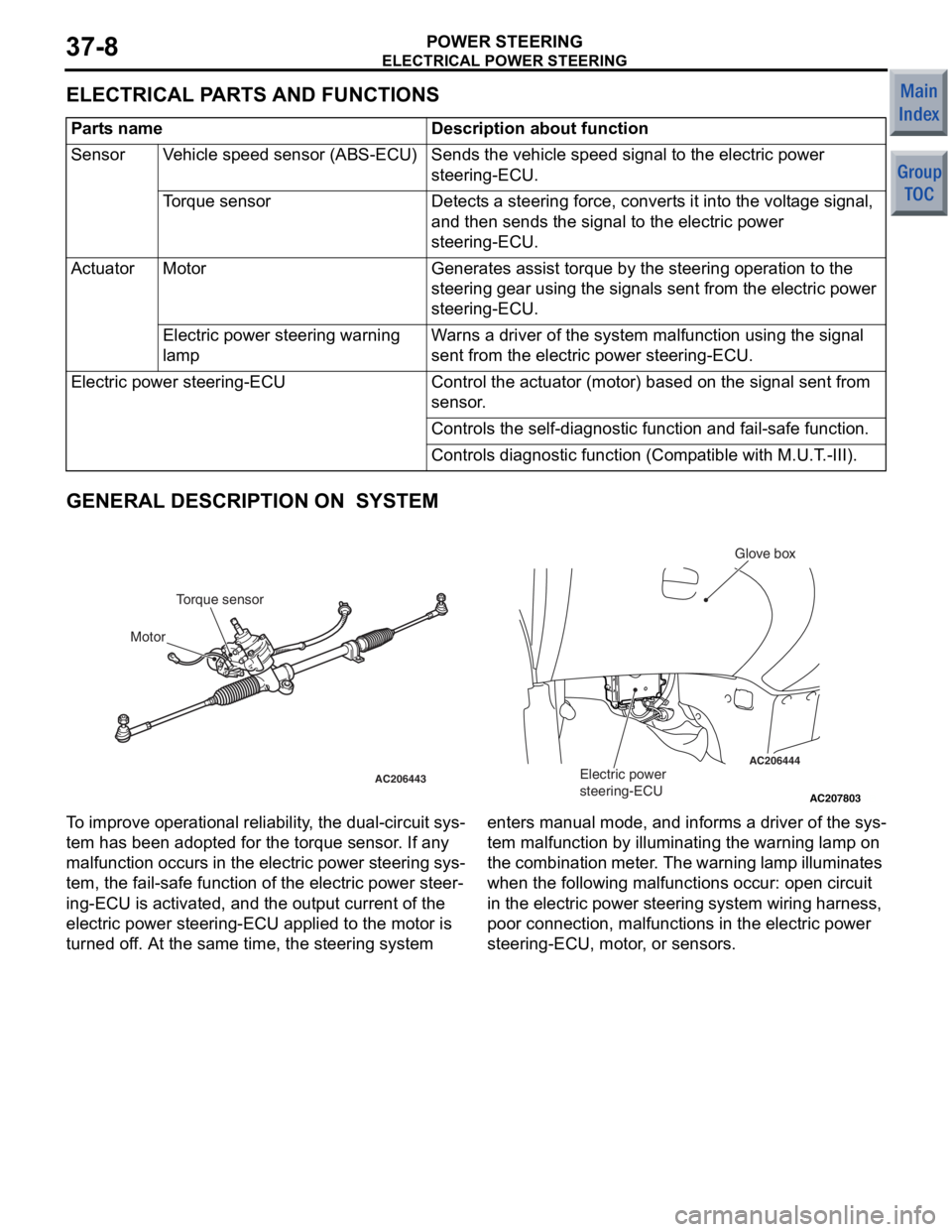
ELECTRICAL PARTS AND FUNCTIONS
Parts nameDescription about function
SensorVehicle speed sensor (ABS-ECU)Sends the vehicle speed signal to the electric power
steering-ECU.
Torque sensorDetects a steering force, converts it into the voltage signal,
and then sends the signal to the electric power
steering-ECU.
ActuatorMotorGenerates assist torque by the steering operation to the
steering gear using the signals sent from the electric power
steering-ECU.
Electric power steering warning
lampWarns a driver of the system malfunction using the signal
sent from the electric power steering-ECU.
Electric power steering-ECUControl the actuator (motor) based on the signal sent from
sensor.
Controls the self-diagnostic fu nction and fail-safe function.
Controls diagnostic function (Compatible with M.U.T.-III).
GENERAL DESCRIPTION ON SYSTEM
AC207803
AC206444
AC206443
AB
Electric power
steering-ECU
Glove box
Torque sensor
Motor
T o improve opera t iona l reliabi lity , th e dual-circuit sys-
tem ha s be en ad opted f o r the t o rque sensor . If a n y
malfunct
i on occurs in the electric power st eering sys
-
tem, the fail-sa f e fun c tio n of th e ele c tric power steer-
ing-ECU is activated, and the ou tput current of the
electric power steerin
g-ECU a pplied to the motor is
turned o
f f. At th e sa me time, the steerin g syste m enters man ual mode, and informs a dr iver of the sys
-
tem malfu
n ction by illuminating th e warnin g lamp on
the
comb in at io n me te r . Th e warn in g la mp il lu min a te s
wh
en the following malfu n ct ions occur: ope n circuit
in the
e l ectric power stee ring system wiring harness,
poor connectio
n , ma lfunction s in the e l ectric power
steering-ECU, mo
tor , or sensors.