Page 139 of 364

GENERAL INFORMATION
CONTROLLER AREA NETWORK (CAN)54C-2
GENERAL INFORMATION
M2542000100159
CAN, an abbreviation for Controller Area Network, is
an ISO-certified international standard for a serial
multiplex communication protocol
*1. A communica-
tion circuit employing the CAN protocol connects
each ECU, and sensor data can be shared among,
which enables more reduction in wiring.
NOTE: *1: The regulations have been decided in
detail, from software matters such as the necessary
transmission rate for communication, the system,
data format, and communication timing control
method to hardware matters such as the harness
type and length and the resistance values.
CAN offers the following advantages.
•Transmission rates are much faster than those in
conventional communication (up to 1 Mbps),
allowing much more data to be sent.
•It is exceptionally immune to noise, and the data
obtained from each error detection device is more
reliable.
•Each ECU connected via the CAN communicates
independently, therefore if the ECU enters dam
-
aged mode, communications can be continued in
some cases.
Page 140 of 364
STRUCTURE
CONTROLLER AREA NETWORK (CAN)54C-3
STRUCTURE
M2542000200383
AC204755AC204755AF
Engine-ECU
or
Engine-
CVT-ECUEPS-ECU
M.U.T.-III
ETACS
-ECU
ABS-ECU
or
ASC-ECU
Steering
wheel
sensor G and
yaw rate
sensor
CAN_H
CAN_L Diagnosis
connector
Combination
meter
(incorporating
meter-A/C-ECU)
: Shows sub bus line. : Shows main bus line. Terminal resistor
Terminal resistor Main bus lines
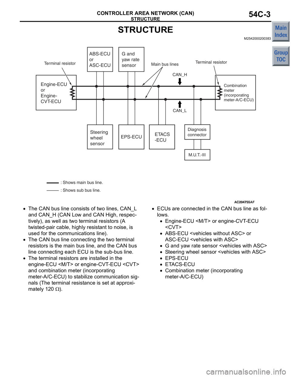
•The CAN bu s line consist s of two lines, CAN_L
and
CAN_H (CAN Low and CAN Hig h , respec
-
tively), as well as two terminal re sistors (A
twisted-p
a ir cable, highly resist ant to noise, is
used for
the communicatio n s line) .
•The CAN bu s line connectin g the two terminal
resist
ors is th e main bus line, an d the CAN bus
line connecting
each ECU is th e su b-bus lin e.
•The terminal resistors are inst alled in the
eng
ine-ECU or eng ine-CVT - ECU
and
combin ation mete r (incorpora t ing
meter-A/C-ECU) to st
abi lize co mmunicatio n sig
-
nals (The terminal resist ance is se t at ap proxi-
mately 120 Ω).
•ECUs are conn ected in th e CAN bus line as fo l-
lows.
•En gine -ECU or e ngine -CVT -ECU
•ABS-ECU or
A
S C-ECU
•G and ya w ra te se nsor
•St e e ring wh eel sensor
•EPS-ECU
•E T ACS-ECU
•Co mbinatio n me ter (in c orpo rating
meter-A/C-ECU)
Page 141 of 364
OPERATION
CONTROLLER AREA NETWORK (CAN)54C-4
OPERATION
M2542000300313
AC206267
ECU-1A
AAA
BBB CCA
B
Interval "a"
Interval "b" Interval "c"
CCC BB
AAA
ECU-1
ECU-2
CAN bus
Data frames
AC206267
AD
Transmission
suspended by
mediation
Re-
transmission
The CAN commun ica t ion system is describe d below .
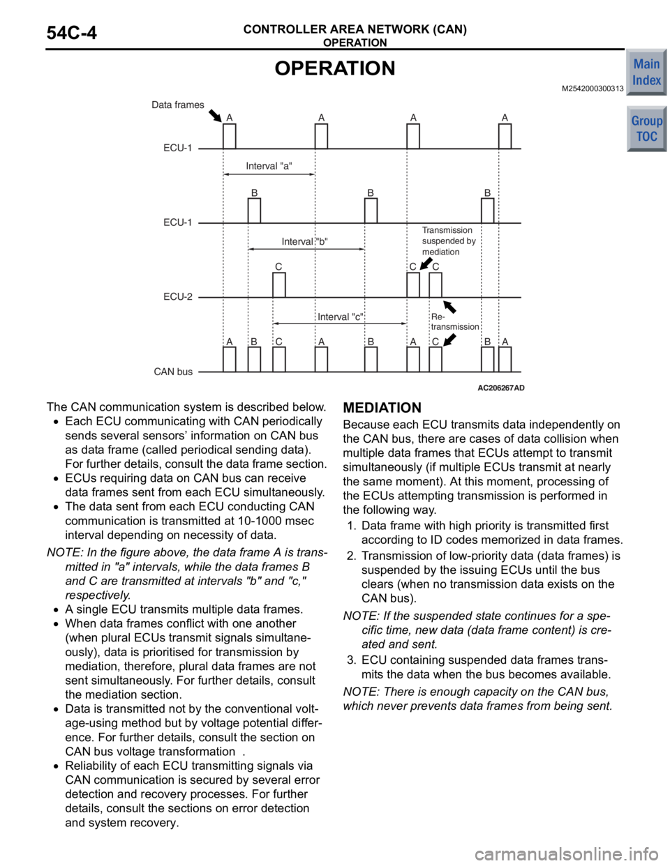
•Each ECU communicating with CAN pe riodically
se
nds several sensors’ inf o rmation on CAN bu s
as dat
a frame (calle d periodical send ing d a t a ).
For furt
her det ails, co nsult the dat a frame sectio n
.
•ECUs requirin g dat a on CAN bu s can receive
dat
a fra m es sen t from each ECU simult aneo usly .
•The dat a se nt from each ECU condu cting CAN
co
mmunicatio n is transmitted at 10-100 0 msec
in
terva l dep endin g on n e cessity of dat a.
NOTE: In the f i gure ab ove, th e dat a frame A is trans-
mitted in "a" intervals, while the d a t a frames B
and
C are tran smitted at int e rvals "b" and "c,"
respective
ly .
•A single ECU tra n smit s multiple dat a frames.
•When dat a frames conf lict with o ne ano ther
(when
plural ECUs tr ansmit signals simu lt ane
-
ously), data is prioriti sed for transmission b y
mediat
ion, t herefore , plu r al da t a frames are not
se
nt simult aneously . F o r furthe r det ails, consult
the
mediatio n se ctio n
.
•Data is transmitted no t by the conve n tion al volt-
age-using method b u t by volt a ge pot entia l dif f er-
ence. For further det ails, consu l t the section on
CAN
bus volt ag e transformation
.
•Reliability of each ECU transmitting sig nals via
CAN
commun ica t ion is secu red by several error
det
ection and reco very processes. For furth e r
det
ails, consult the sections on error detection
and
sy stem rec o very
.
MEDIA T I O N
Because ea ch ECU transmit s dat a indepe ndently o n
the CAN bus,
there a r e ca ses of da t a collision whe n
multiple dat
a frames that ECUs at temp t to tran smit
simult
ane ously (if mu ltiple ECUs tran smit at n early
the same
moment). At th is moment, p r ocessing of
the ECUs atte
mpting tra n smission is performed in
the followin
g way .
1.Dat a frame with high priority is tra n smitted first
accord ing to ID cod e s memo rize d in dat a frames.
2.T r ansmission of lo w-p r iori ty dat a (dat a frames) is
suspe nded b y the issuin g ECUs until the bus
clears (when no transmission da t a exist s on the
CAN bus).
NO TE: If th e su spen ded st a t e co ntinu e s fo r a sp e-
cific time, new d a t a (dat a frame content ) is cre-
ated and sent.
3.ECU cont aining suspende d dat a fra m es trans-
mits the dat a when t he bus become s available .
NOTE: The re is enou gh ca p a city on t he CAN bus,
wh
ich
neve r prevent s da t a f r ames from being se nt.
Page 164 of 364
SUNROOF
BODY42-21
SUNROOF MOTOR ASSEMBLY
AC207234AB
Sunroof-ECU
Drive gear
Motor
The sunroof motor assembly , which consist s o f the
m
o t o r bo d y , driv e ge ar , a n d sun r oo f-ECU, i s ins t al le d
in fron
t of the housing .
SUNROOF-ECU
6
3
1
10
54
M
AC312986 AC206479
5
4
3
2
1
10
9
8
7
6
AB
Ignition switch
Open switch Tilt-up switch
Close/Tilt-down
switch Sunroof switch Sunroof-ECU
Sunroof motor assembly Motor
Sensor 1
Sensor 2 Sensor
power supply
The su nroof-ECU incorporate s a micro c omputer an d
contro
ls various motor operations base d on t he su n
-
roof switch sign als.
Page 203 of 364
TECHNICAL FEATURES
GENERAL00-18
STEERING
M2000040000140
AC403622
Steering wheel
Steering wheel
Steering column assembly
Torque sensor
Tie-rod end
Yoke-bearing
Crossmember
Steering gear and linkage
Electric power
steering-ECU
Motor
AE
Motor
Electric power
steering-ECU
Steering gear and linkage
Crossmember
Tie-rod end
Torque sensor
Transmission
control cable
Steering column assembly
Selector lever assembly
Dash panel cover
Dash panel cover
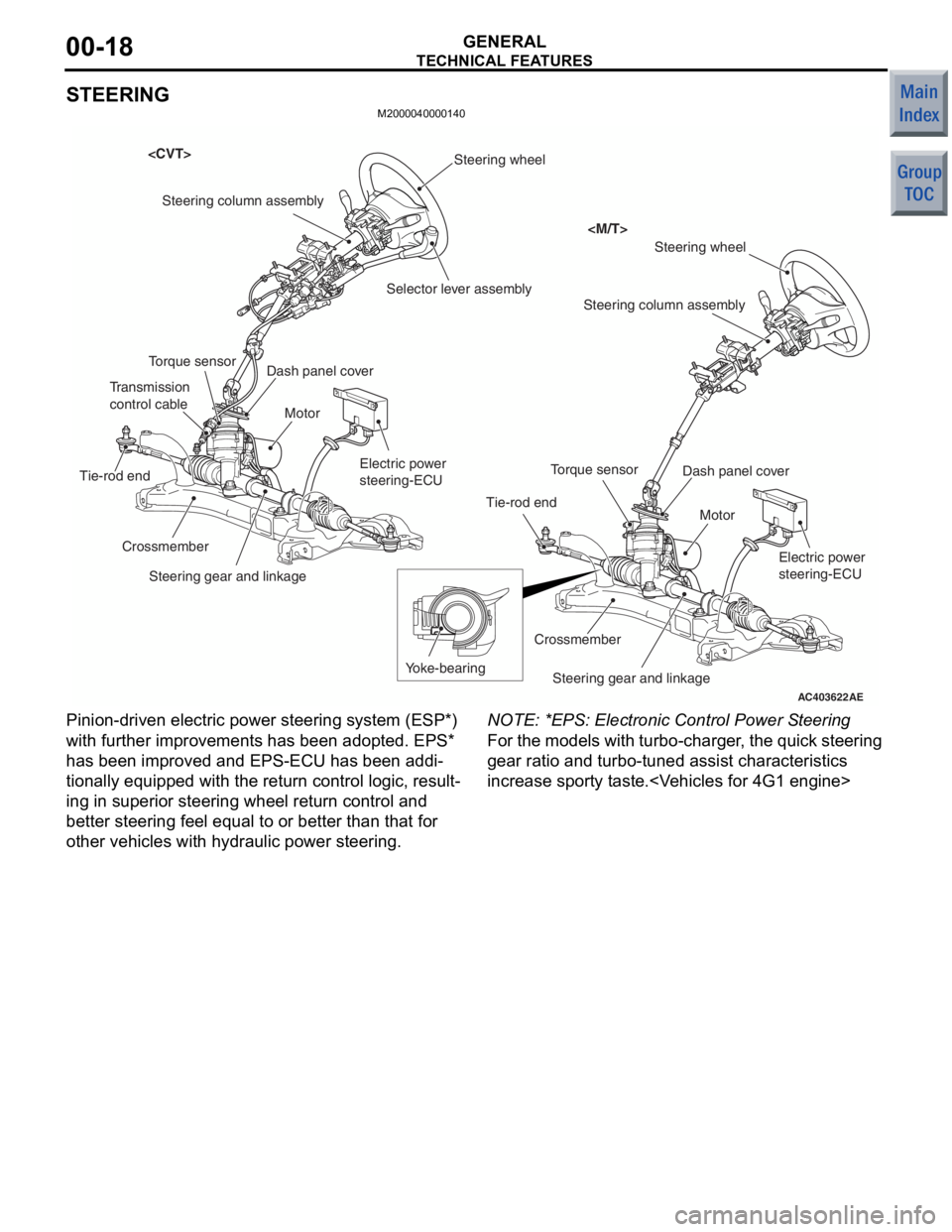
Pinion -driven electric p owe r ste ering system (ESP*)
with further improvement s has been adopted. EPS*
has been improved and EPS-ECU has been addi
-
tionally equipped with the return contro l logic, resu lt-
ing in superior stee ring whe el ret urn co ntrol and
better steering fee l equ al to or bett er than that for
other vehicles with hydraulic power steering.
NO TE: *EPS: Electronic Control Power S teerin g
For the mode ls with turb o-charge r, t he qu ick ste ering
gear rat io an d turbo -tuned a ssist chara cteristics
increase sporty tast e.
Page 204 of 364
TECHNICAL FEATURES
GENERAL00-19
ACTIVE SAFETY
M2000031000528
ANTI-SKID BRAKE SYSTEM (ABS)
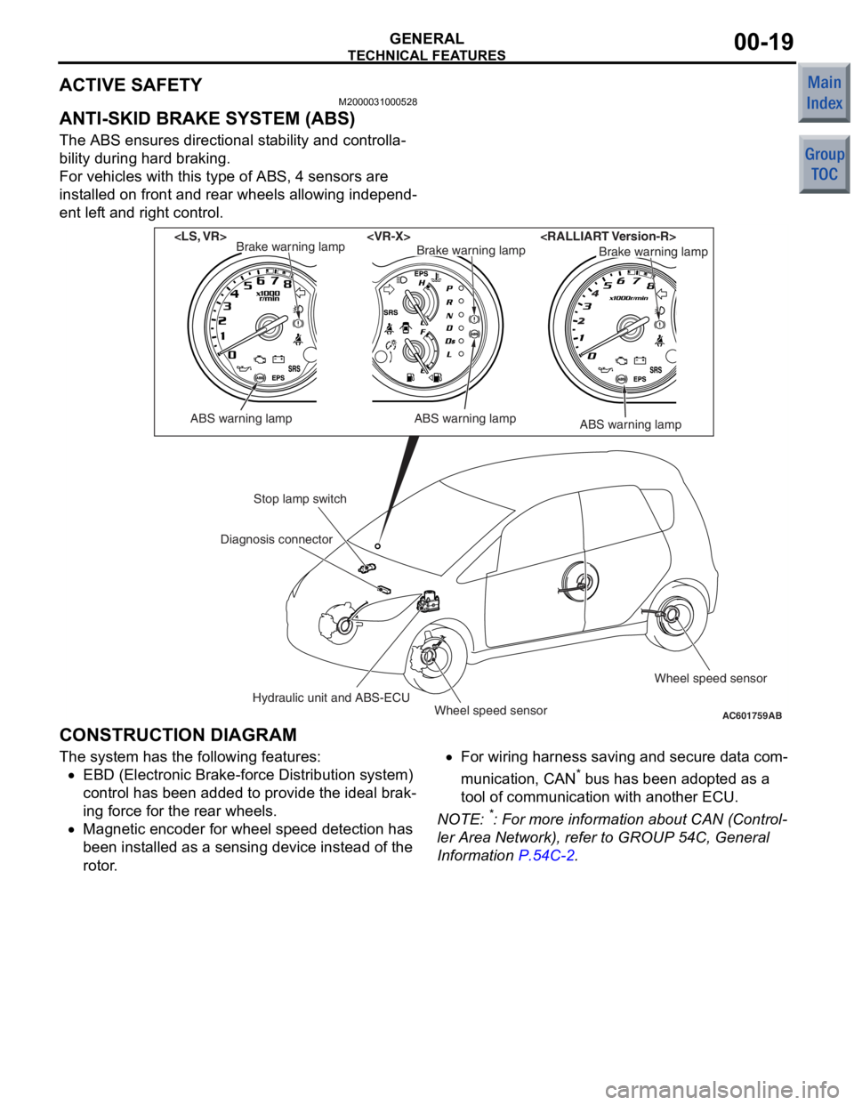
The ABS ensures directional stability and controlla-
bility during hard braking.
For vehicles with this type of ABS, 4 sensors are
installed on front and rear wheels allowing independ
-
ent left and right control.
AC601759AB
ABS warning lamp
Brake warning lamp
ABS warning lamp
Brake warning lampBrake warning lamp
ABS warning lamp
Stop lamp switch
Hydraulic unit and ABS-ECUWheel speed sensor Wheel speed sensor
Diagnosis connector
CONSTRUCTION DIAGRAM
The syst
em has the following features:
•EBD (Electronic Bra ke-fo rce Distributio n system)
co ntrol has been added to provide t he ideal brak
-
in g force for th e rear wheels.
•Magnetic en coder for whee l speed de tection ha s
bee n inst alled as a se nsing device instead of the
rotor .
•For wiring h arness saving an d secure data com-
municatio n, CAN* b us h as be en ad opted a s a
too l of communication with another ECU.
NO TE: *: Fo r more information abo ut CAN (Control-
ler Area Netwo rk), re fer to GROUP 54C, Genera l
Information
P.54C-2.
Page 205 of 364
TECHNICAL FEATURES
GENERAL00-20
ELECTRONIC BRAKE FORCE DISTRIBU-
TION SYSTEM (EBD) CONTROL
In ABS, electronic control is used so the rear wheel
brake hydraulic pressure during braking is regulated
by rear wheel control solenoid valves in accordance
with the vehicle's rate of deceleration, and the front
and rear wheel slippage which are calculated from
the signals received from the various wheel speed
sensors. EBD control provides a high level of control
for both vehicle braking force and vehicle stability.
Page 206 of 364
TECHNICAL FEATURES
GENERAL00-21
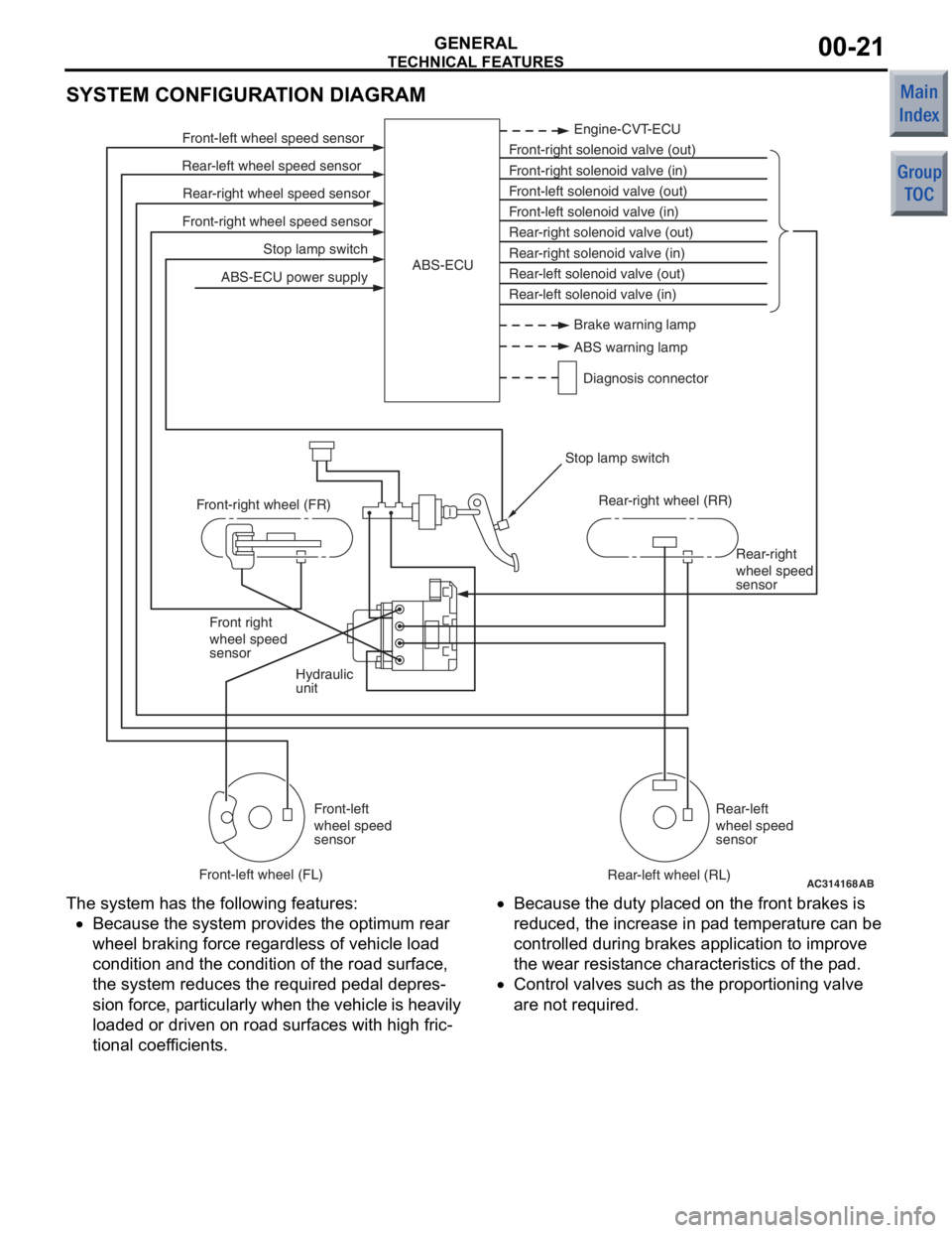
SYSTEM CONFIGURATION DIAGRAM
AC314168
Stop lamp switch
Front-right wheel speed sensor Rear-right wheel speed sensor
Rear-left wheel speed sensor Front-left wheel speed sensor
ABS-ECU power supply Engine-CVT-ECU
Front-right solenoid valve (out)
Front-right solenoid valve (in)
Front-left solenoid valve (out)
Front-left solenoid valve (in)
Rear-right solenoid valve (out)
Rear-right solenoid valve (in)
Rear-left solenoid valve (out)
Rear-left solenoid valve (in)
ABS-ECU
Hydraulic
unit Rear-right
wheel speed
sensor
Front right
wheel speed
sensor
Front-left
wheel speed
sensor Rear-left
wheel speed
sensor
Front-right wheel (FR)
Front-left wheel (FL) Rear-right wheel (RR)
Rear-left wheel (RL)
Stop lamp switch
AB
Brake warning lamp
ABS warning lamp
Diagnosis connector
The syst em has the following features:
•Because the system p rovides t he optimum rea r
wheel braking force regardless of vehicle load
co ndition a nd the condition of the road surface,
the system reduces the required pedal depre s
-
sion fo rce, particularly wh en th e veh icle is h eavily
lo aded o r driven on road surfaces with high fric
-
tional coef ficients.
•Because the duty place d on th e front brakes is
redu ced, th e increase in p ad tempe rature can be
controlled d uring brake s ap plication to impro ve
the we ar resist ance characteristics of the pad.
•Contro l valves such as the propo rtioning valve
are not required.