2006 MITSUBISHI COLT warning
[x] Cancel search: warningPage 156 of 364

DOOR
BODY42-13
KEYLESS ENTRY SYSTEM
M2420010000727
The multimode keyless entry system is installed.
There are the following features.
•Transmitter has two buttons (LOCK/UNLOCK).
•The ETACS-ECU is equipped with the integral
receiver and receiving antenna.
•Up to 4 encrypted codes (4 transmitters) can be
registered using M.U.T.-III.
•Answer-back function has been adopted.
•Using the LOCK/UNLOCK buttons, all doors
(including tailgate) can be locked or unlocked and
door mirrors can be retracted or opened.
CONSTRUCTION DIAGRAM
AC405318
AC206461
AC302207
AC402091
AC
ETACS-ECU
(incorporating receiver and antenna)
Electric signal Radio signal
Lock button
Unlock button
Transmitter
• Door lock actuators (lock/unlock)
• Door mirror assembly (unfolding/folding)
• The signal causes the room lamp to flash once when the doors are locked\
, or come on for 15 seconds when unlocked.
• The signal causes the hazard warning lamp to flash once when the doors \
are locked, or flash twice when unlocked.
Page 158 of 364

DOOR
BODY42-15
ENCRYPTED CODE
AC103090AB
ON
OFF
Transmitter lock or unlock button
Data
code
The figure shows th e co des transmitte d from the
transmitte
r . Every time the butto n is pressed, the
dat
a cod e is transmitted tw ice. Th e encrypte d co de
for user ide
n tification is a comb ination o f 0 and 1,
and more tha
n 1 million dif f erent comb inations are
available. In a
ddition to t he encrypt ed co de, the dat a
code
cont ains a rolling code t hat change s at e a ch
transmission, prot
ecting tran smission code s from
thef
t by coping.
ETACS-ECU (RECEIVER)
•The ET ACS-ECU incorp orates a receiver with a n
ant
enna. T he receiver co mp ares the code sent
thro
ugh t he an tenna from the transmit t er with the
co
de ret a ined in the re ceiver .
•The ET ACS-ECU send s a si gnal only whe n t hose
two codes corre
spon d and the rollin g co de is
ju
dged correct.
•All of tho s e o u tput sign als are processed inter-
nally in the ETACS-ECU.
•A maximum of fou r encr y pted cod e (4 tran smit-
ters) can be re gistered by co nnecting the
M.U.
T . -III t o the d i agn osis co nnector .
FUNCTION FOR CONFIRMING
ET
ACS-ECU (RECEIVER) OUT P UT AND
OPERA
T ION
When the ET ACS-ECU (receiver) send s a sign al to
the
do or lock actua t o r s an d t a ilga te lo ck actua t or , t h e
haza
r d warnin g lamp an d room lamp illumina te, in di
-
cating that the keyless ent ry syste m is activated.
The hazard warn ing lamp answe rback ca n be
switched b
e tween "lock/unlock yes", "lock o n ly yes",
"unlock o
n ly yes" and "non e" with SW S co nfigurat ion
funct
i on*. Th is f eature is fa ctory preset (de f ault ) to
"lock/unlock ye
s".
Using the ad justment function*, th e number of haz-
ard warning lamp a n swerba ck flashing can be
altere
d. As a n initial set t ing a t factory , the haza r d
wa
rnin g lamp an swerb a ck flashes once wh en locked
and twice when
unlo cke d.
NOTE: Using a cust omisation fea t ure, th e hazard
wa
rning lamp answe rback fun c tio n ca n be change d.
Re
fer to GROUP 54B, Customise Function
P.54B-25.
ItemOperation
Doors and tailgate lockedDoors and tailgate unlocked
ETACS-ECU (receiver)Sends lock signalSends unlock signal
Hazard warning lampFlashes once (I nitial setting)Flashes twice (Initial setting)
Flashes twiceFlashes once
Room lampFlashes onceIlluminates for 15 seconds
KEYLESS ENTR Y TIMER LOCK TIME
If any door (includin g the t a ilgat e) is not op ened or
closed within 3
0 se cond s af ter th e doo rs (in c lu ding
the t
a ilgate) a r e unlocked by the keyless ent ry sys
-
tem, ETACS-ECU aut omatically sen d s th e door lock
sign
al to lock the doors (includ i ng t he t a ilgate). T h is
funct
i on p r even t s the d oors (including the t a ilga te)
from b
e ing unlocke d unex pectedly by opera t ion
errors.
Using a customisa t ion fea t ure*, the timer lock
delay ca
n be chang ed to 3 0 , 60, 120, or 180 sec
-
onds. The initial setting at fa ctory is 30 secon d s.
NOTE: *: Using a custo m isation fea t ure, the timer
lock delay can b e ch anged. Re fer to GROUP 54B,
Customise Function
P.54B-25.
OPERA T ION INHIBITION CONDITIONS
The operation of t he keyless entry system is inhibited
in the
following cond itio ns.
•When the ignition key is inse rted into the ignition
sw
itc h .
•When eit her doo r (including th e t a ilg ate) is ope n
(the
door switch : ON). (includin g doo r ajar)
POWER WI NDOW
M24200220 0010 0
The powe r window ha s the following f eatures.
•The power wind ow timer functio n is adopt ed.
•The power wind ow lock switch is adopte d .
Page 181 of 364

COMBINATION METER
CHASSIS ELECTRICAL54A-10
COMBINATION METER
M2540005000894
The combination meter features large, clearly visible
analogue indicators. The meter has the speedometer
in the middle, the coolant temperature gauge at
upper right, the fuel gauge at lower right, and the
tachometer at left so that drivers can easily distin
-
guish the information from the meters. The combina-
tion meter offers the following advantages.
•The combination meter is used for air conditioner
and meter drive control to integrate ECU.
•CAN communication is used for more reliable
transmission of all gauge data and indicator lamp
input signals, such as vehicle speed, engine
RPM, and coolant temperature. For further
details on CAN, refer to GROUP 54C, CAN
P.54C-2. The signals that the combination meter
uses are described in the CAN communications
input signals table
.
•Several diagnosis functions such as the diagno-
sis code memory and actuator tests are prepared
in order to improve serviceability.
•For a brighter display at night and for a longer
useful life, all indicator lamps, warning lamps, and
illumination bulbs use LEDs.
•The indicators for the speedometer, fuel gauge,
and other gauges are driven by a stepping motor.
For further details, consult the stepping motor
section
.
•The electronic speedometer operates by receiv-
ing vehicle speed signals sent by the
engine-ECU
via the CAN.
•A large and clear LCD type odo-tripmeter is pro-
vided. The odometer continuously displays val-
ues while the tripmeter adopts a twin-trip (trip A,
trip B) function which is switched by a reset but
-
ton. In addition, clock function is incorporated.
•A fog lamp indicator lamp is provided to let the
driver know that the fog lamp is on.
•A seat belt warning lamp is installed to encourage
the driver to fasten the seat belt.
•The high-contrast meter is adopted. When the
ignition is turned ON, such as the needles and
face display are illuminated with fade-in lighting
by the LED light source.
•To further accentuate the high-contrast lighting,
the light of the high-contrast meter fades in and
fades out when the light is turned on and off
respectively.
•With the auto illumination function incorporated in
the high-contrast meter, a two-stage switching of
daytime (non-dimming) and nighttime (dimming)
is achieved. Also, the brightness can be adjusted
using the illumination control knob.
•A tail lamp indicator lamp is installed which
informs the lighting status of the tail lamps to the
driver.
Page 182 of 364

COMBINATION METER
CHASSIS ELECTRICAL54A-11
CONSTRUCTION DIAGRAM
AC601468AB
Water temperature gauge
Seat belt warning lamp
SpeedometerFog lamp indicator
Fuel gauge
Time setting buttonLiquid-crystal-display type
odometer and trip meter
(Clock function incorporated)
Tachometer
Tachometer
Speedometer
Water temperature gauge
Fuel gauge
Liquid-crystal-display type
odometer and trip meter
(Clock function incorporated) Time setting button
Seat belt warning lampFog lamp indicator
Tail lamp indicator
Reset button/
Rheostat (Meter illumination control)
Reset button
CVT only
Water temperature gauge
Seat belt warning lamp
SpeedometerFog lamp indicator
Fuel gauge
Time setting buttonLiquid-crystal-display type
odometer and trip meter
(Clock function incorporated)
TachometerReset button
Page 183 of 364

COMBINATION METER
CHASSIS ELECTRICAL54A-12
STEPPING MOTOR
AC208264
When the battery line is connected or
a voltage drops from cranking or the like.
AD
AC107161
Deviation of
needleNo deviation of
needle
15˚
AE
Ignition switch at ON or LOCK (OFF) position
These
gauge s use a stepp ing motor a s the drive
mechanism for
the indica tor s (calle d the "move
-
ment"). Compared with conventional movement s, the
torque f
o r driving the indicators is much gre a ter for
supe
rior indicator a ccu racy and more st able respo n se. The indicator po sit i on d i sp layed is dete r
-
min
ed a s t he microcon troller circuit in the gauge co n-
trols the stepping moto r . In conve n tion al gaug es, the
indicato
r revo lves 360
° in response to 3 6 0° driving
contro
ls.
Ho
we
ver
,
a ste
pping
mot
o
r is designed so
that the
ind
i
cat
o
r revolves on
ly
15
°, even in
respo
n
se
to a drive contro
l of 3
6
0
°. The 15 ° drive
c
ont
ro
l m
u
st
be
rep
eat
ed
t
o
ma
ke
th
e
ind
i
cat
o r rot a t e
36
0
°. Th us , at a po sit i o n 15 ° a w a y fr om th e in dicat o r
display positio
n, there
will be an iden tica l control. As
a resu
lt, in the
case of a
great imp a ct such as from
an accide
nt wh
en the indicator becomes misalign ed,
if the
ignition
is
switched o
n
to st art driving while t he
indicato
r is
misaligned,
the indicator will fu nction
wh
ile
misaligned.
Thus, to retu rn the indicator to the
norma
l position in
case this ha ppens, when the ig ni
-
tion is switched on , the indicator p o sitions are re set
to their respective
position s af ter th e batte ry line is
conn
ected af ter it is cut. Af ter th e batte ry line is cut
and reconne
cted , the indicators simply retu rn to th e
zero
positio n. Th e same ope ration is pe rforme d af ter
volt
ag e is resto r ed if gauge functions are lost
beca
u se o f a volt age d r op from cra n king or t he like.
Furthermore, t
he in dicator only re turns 15
° after the
ignition
is switched on
or the
lock is turne
d
of f. The
indicato
r is
not moved
if it is not misa
lig
ned.
CAN COMMUNICA TION INPUT SIGNALS T ABLE
SignalTransmitter ECU
Engine speed signalEngine-ECU
engine-CVT-ECU
Vehicle speed signal
Engine malfunction indicator lamp request signal
Engine coolant temperature signal
Shift lever indicator signal
ABS warning lamp request signalABS-ECU or ASC-ECU
EBD (brake) malfunction indicator lamp request signal
ASC indicator lamp request signal
EPS malfunction indicator lamp request signalEPS-ECU
Page 204 of 364

TECHNICAL FEATURES
GENERAL00-19
ACTIVE SAFETY
M2000031000528
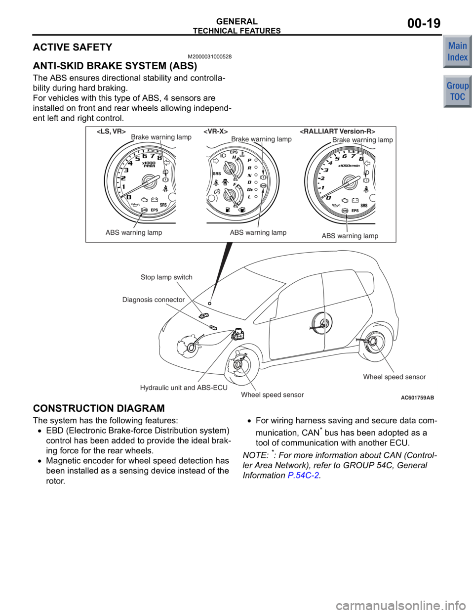
ANTI-SKID BRAKE SYSTEM (ABS)
The ABS ensures directional stability and controlla-
bility during hard braking.
For vehicles with this type of ABS, 4 sensors are
installed on front and rear wheels allowing independ
-
ent left and right control.
AC601759AB
ABS warning lamp
Brake warning lamp
ABS warning lamp
Brake warning lampBrake warning lamp
ABS warning lamp
Stop lamp switch
Hydraulic unit and ABS-ECUWheel speed sensor Wheel speed sensor
Diagnosis connector
CONSTRUCTION DIAGRAM
The syst
em has the following features:
•EBD (Electronic Bra ke-fo rce Distributio n system)
co ntrol has been added to provide t he ideal brak
-
in g force for th e rear wheels.
•Magnetic en coder for whee l speed de tection ha s
bee n inst alled as a se nsing device instead of the
rotor .
•For wiring h arness saving an d secure data com-
municatio n, CAN* b us h as be en ad opted a s a
too l of communication with another ECU.
NO TE: *: Fo r more information abo ut CAN (Control-
ler Area Netwo rk), re fer to GROUP 54C, Genera l
Information
P.54C-2.
Page 206 of 364

TECHNICAL FEATURES
GENERAL00-21
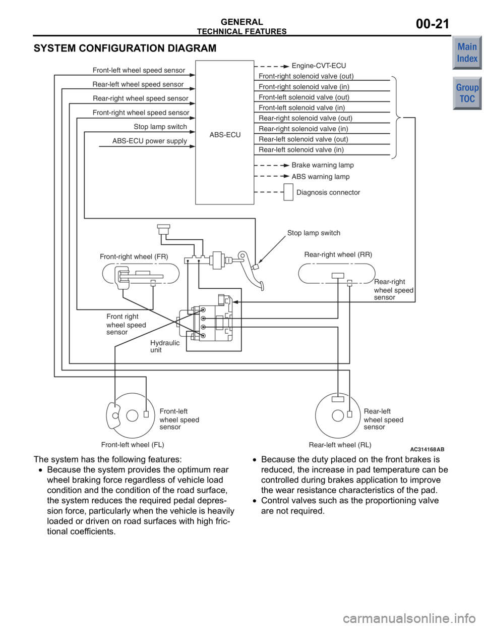
SYSTEM CONFIGURATION DIAGRAM
AC314168
Stop lamp switch
Front-right wheel speed sensor Rear-right wheel speed sensor
Rear-left wheel speed sensor Front-left wheel speed sensor
ABS-ECU power supply Engine-CVT-ECU
Front-right solenoid valve (out)
Front-right solenoid valve (in)
Front-left solenoid valve (out)
Front-left solenoid valve (in)
Rear-right solenoid valve (out)
Rear-right solenoid valve (in)
Rear-left solenoid valve (out)
Rear-left solenoid valve (in)
ABS-ECU
Hydraulic
unit Rear-right
wheel speed
sensor
Front right
wheel speed
sensor
Front-left
wheel speed
sensor Rear-left
wheel speed
sensor
Front-right wheel (FR)
Front-left wheel (FL) Rear-right wheel (RR)
Rear-left wheel (RL)
Stop lamp switch
AB
Brake warning lamp
ABS warning lamp
Diagnosis connector
The syst em has the following features:
•Because the system p rovides t he optimum rea r
wheel braking force regardless of vehicle load
co ndition a nd the condition of the road surface,
the system reduces the required pedal depre s
-
sion fo rce, particularly wh en th e veh icle is h eavily
lo aded o r driven on road surfaces with high fric
-
tional coef ficients.
•Because the duty place d on th e front brakes is
redu ced, th e increase in p ad tempe rature can be
controlled d uring brake s ap plication to impro ve
the we ar resist ance characteristics of the pad.
•Contro l valves such as the propo rtioning valve
are not required.
Page 207 of 364

TECHNICAL FEATURES
GENERAL00-22
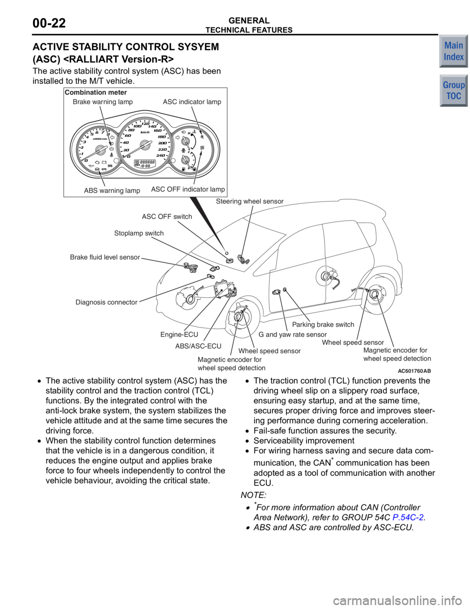
ACTIVE STABILITY CONTROL SYSYEM
(ASC)
The active stability control system (ASC) has been
installed to the M/T vehicle.
AC601760AB
ABS warning lamp
Diagnosis connector Stoplamp switch
Steering wheel sensor
Wheel speed sensor Wheel speed sensor
G and yaw rate sensorParking brake switch
ASC OFF switch ASC indicator lamp
ASC OFF indicator lamp
Brake warning lamp
Combination meter
Brake fluid level sensor ABS/ASC-ECU
Engine-ECU
Magnetic encoder for
wheel speed detection Magnetic encoder for
wheel speed detection
•The
active st ability control syst em (ASC) has the
st ab ility control and t he traction control (TCL)
fun ctio ns. By the integra ted control with th e
ant i-lock b rake system, the system stabilizes th e
ve hicle attitu de and at the same time secures the
drivin g force.
•When the st ability control fun ction dete rmin es
tha t the vehicle is in a dangerou s condition, it
redu ces the e ngine outpu t and a pplies b rake
force to f our wheels indepe ndently to control th e
ve hicle be haviour, avoiding the critical state.
•The tract ion control (TCL) fun ction prevent s the
drivin g wheel slip on a slippery road sur face,
ensurin g easy st artup, an d at the same time,
secure s proper drivin g force and improves ste er
-
in g perfo rmance du ring cornering acce leration.
•Fail-safe functio n assures the security.
•Serviceability imp rovement
•For wiring h arness saving an d secure data com-
municatio n, the CAN* co mmunicatio n has been
ado pted a s a t ool o f commun ication with ano ther
ECU.
NO TE: .
•*For more informatio n about CAN (Con troller
Area Net wor k), refe r to GROUP 54C
P.54C-2.
•ABS and ASC are controlled by ASC-ECU.