Page 63 of 364
BASE ENGINE
ENGINE MECHANICAL <4A9>11A-15
MIVEC (MITSUBISHI INNOVATIVE VALVE TIMING ELECTRONIC CONTROL SYSTEM)
AK300856AD
A
A
A-A
Oil feeder control valve
Oil feeder
control
valve filter
Oil feeder
control
valve filter
bolt
Cylinder head
Cylinder block
V.V.T.sprocket
M I VEC (Mit su bis h i Inn o va tive V a lve tim i ng Elect r o n ic
Con
t rol system) consist s of th e compon ent s illus
-
trated above .
The int a ke valve timing is optimally controlled (con-
tinuously variable) un der the chan ging driving condi-
tions to improv e po we r in th e entire sp eed ra nge.
V. V . T . SPROCKET (V ARIABLE V A L V E TIMING SPROCKET)
AK300857
Vane bushing
AB
SprocketVane roter
V.V.T.sprocket
bolt
Timing mark
Vane housing
Advance oil chamber
Retard oil chamber
Stopper pin
Oil from the oil fe
eder control valve is sent t o the
V
. V . T . sp rocket, moving the vane roto r and thus reg u
-
lating the valve timing.
Page 66 of 364
GENERAL INFORMATION
ENGINE MECHANICAL <4A9>11A-18
GENERAL INFORMATION
M2112000101009
The newly developed 1.5L 4A91 engine features
4-cylinder, 16-valve, and double overhead camshafts
(DOHC).
The engine has the following features.
•Aluminum cylinder block
•MIVEC (Mitsubishi Innovative Valve timing Elec-
tronic Control system)
•Selective valve tappet of direct acting valve sys-
tem for valve clearance adjustment
•Timing chain
MAJOR SPECIFICATIONS
Item4A91
Total displacement mL1,499
Bore × Stro ke mm75 × 84.8
Compression ratio10.0
Compression chamberPentroof-type
Va l v e t i m i n gIntake openingBTDC 31° − AT D C 1 9°
Intake closingABDC 21° − ABDC 71°
Exhaust openingBBDC 39°
Exhaust closingATDC 5°
Maximum output kW (PS)/rpm77 (104)/6,000
Maximum torque N⋅m (kg⋅m)/rpm141 (14.4)/4,000
Fuel systemElectronically controlled multipoint fuel injection
Ignition systemElectronic-controlled 4-coil
Page 69 of 364
BASE ENGINE
ENGINE MECHANICAL <4A9>11A-21
CYLINDER BLOCK
AK402339AC
Front view
Right side view
Under view
Top view
Rear view
Left side view
Thermostat case installation positionOil filter bracket installation position Front
Front Front Front
Nipple
The cylinder b
l ock is ma de of ligh twe i ght aluminum
allo
y .
The crankshaf t jo urnal is supp orted b y 5 b earing s .
The crankshaf
t thru st load is supporte d by No . 4
bearin
g.
The water jacket is of a full-siamese de sig n .
A nipple is p r ovid ed at the fr o n t of the block to su pply
engin
e oil onto the timin g ch ain.
ItemDimension
Overall height mm280
Overall length mm375.1
Top face to crankshaft
center mm205
Crankshaft center to
bottom face mm75
Bore mm75
Bore pitch mm83
Stroke mm84.8
Page 73 of 364

BASE ENGINE
ENGINE MECHANICAL <4A9>11A-25
CRANKSHAFT
AK305068AD
Oil pump drive
gear shaft
Crankshaft
sprocket
Crankshaft sensing ring
CrankshaftOil hole
Oil hole
Balance weightBalance weightBalance weight
A casted crankshaf
t is used for t he cr ankshaf t.
The crankshaft consist s o f 5 ma in be aring s an d 8
balan
ce weight s.
The crankshaft pins a r e arrang ed at 1 8 0° inte rval s.
The oil hole supply lu brication oil from t he jo urnal to
the crank p
i n.
A cranksha f t sprocket and an oil pump drive gea r
shaf
t are press-fit t ed on to the f r ont of the crankshaf t.
The crankshaft is also fitt ed with a crankshaf t sens-
ing ring.
CRANKSHAFT BEARING, THRUST BEARING
AK305070
Upper bearingOil groove
Oil hole
Identification
color
Lower bearing
Identification
color
AB
Thrust bearing
Groove
Front
The upp er cra n kshaf t bea ring (with oil groove) is
loca
ted on the cylinder block side wh ile the lo we r
bearin
g (witho ut oil groo ve) is he ld by the b earin g
cap.
The crankshaft bea ring is e quipp ed with back me t a l.
While the b
earin g it self is ma de of a l uminum alloy ,
the back met
a l is no rmally made of steel sheet .
A thrust bearing is inst alle d on b o th sides of th e No.
4 cran
kshaf t bearing.
ItemDimension
Crankshaft
bearingWidth mm16
Thickness mm20
Crankshaft
thrust bearingThickness mm3.275
Page 76 of 364

BASE ENGINE
ENGINE MECHANICAL <4A9>11A-28
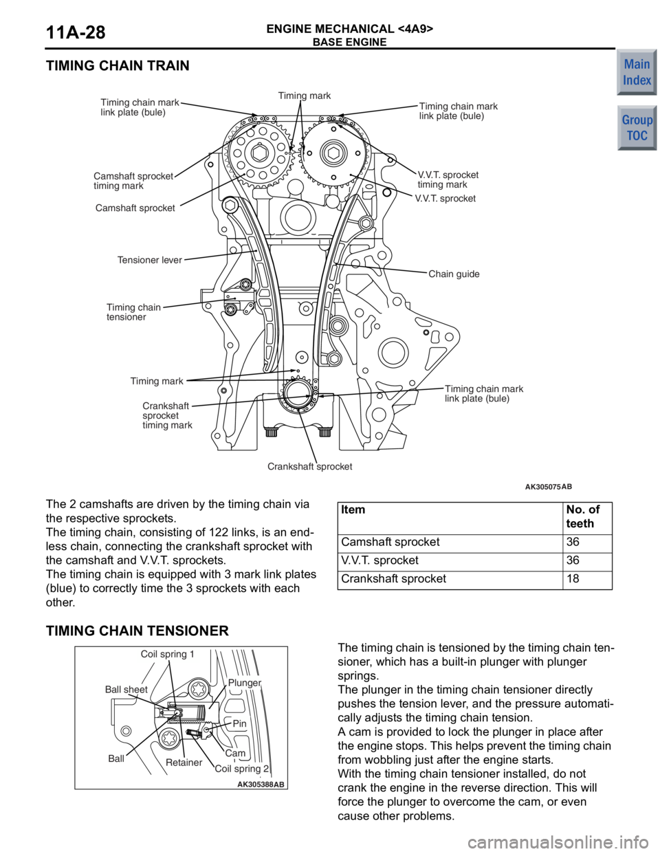
TIMING CHAIN TRAIN
AK305075
V.V.T. sprocket
AB
V.V.T. sprocket
timing mark
Timing chain mark
link plate (bule)
Camshaft sprocket
Camshaft sprocket
timing mark Timing chain mark
link plate (bule)
Timing chain mark
link plate (bule)
Crankshaft
sprocket
timing mark
Crankshaft sprocket
Timing mark
Timing chain
tensioner
Tensioner lever
Chain guide
Timing mark
The 2 camshaf
t s are driven by the t i ming chain via
the res
pec tive spro cke t s .
The timing cha i n, consist i ng o f 122 links, is an end-
less chain, conn ecting the cran ksh af t spro cke t with
the camshaf
t and V . V . T . spro cke t s .
The timing cha i n is eq uippe d with 3 mark link p l ates
(blue)
to co rrectly time t he 3 sprocket s with each
other
.
ItemNo. of
teeth
Camshaft sprocket36
V.V.T. sprocket36
Crankshaft sprocket18
TIMING CHAIN TENSIONER
AK305388AB
Retainer
Ball
Coil spring 1
Ball sheet
Coil spring 2
Cam
Pin
Plunger
The timing chain is tensione
d by th e timing chain te n-
sioner , which ha s a b u ilt-in plunge r with plunge r
springs.
The plunger in the timing chain tension e r dire ctly
push
e s th e tension lever , and the pre s sure aut omati
-
cally ad just s the timing chain tension.
A cam is provided t o lock th e plu nger in pla c e a f te r
the eng
ine stop s. This help s prevent the timing chain
from wob
b lin g just af ter th e eng ine st a r t s .
With the timing cha i n ten s io ner in st alled, do not
crank the
engin e in the reverse directio n. This will
force
the plunger to overcome the cam, or e v en
cause oth
e r problems.
Page 79 of 364
BASE ENGINE
ENGINE MECHANICAL <4A9>11A-31
MIVEC (MITSUBISHI INNOVATIVE VALVE TIMING ELECTRONIC CONTROL SYSTEM)
AK300856AD
A
A
A-A
Oil feeder control valve
Oil feeder
control
valve filter
Oil feeder
control
valve filter
bolt
Cylinder head
Cylinder block
V.V.T.sprocket
M I VEC (Mit su bis h i Inn o va tive V a lve tim i ng Elect r o n ic
Con
t rol system) consist s of th e compon ent s illus
-
trated above .
The int a ke valve timing is optimally controlled (con-
tinuously variable) un der the chan ging driving condi-
tions to improv e po we r in th e entire sp eed ra nge.
V. V . T . SPROCKET (V ARIABLE V A L V E TIMING SPROCKET)
AK300857
Vane bushing
AB
SprocketVane roter
V.V.T.sprocket
bolt
Timing mark
Vane housing
Advance oil chamber
Retard oil chamber
Stopper pin
Oil from the oil fe
eder control valve is sent t o the
V
. V . T . sp rocket, moving the vane roto r and thus reg u
-
lating the valve timing.
Page 89 of 364

GENERAL INFORMATION
ENGINE LUBRICATION12-2
GENERAL INFORMATION
M2120000100175
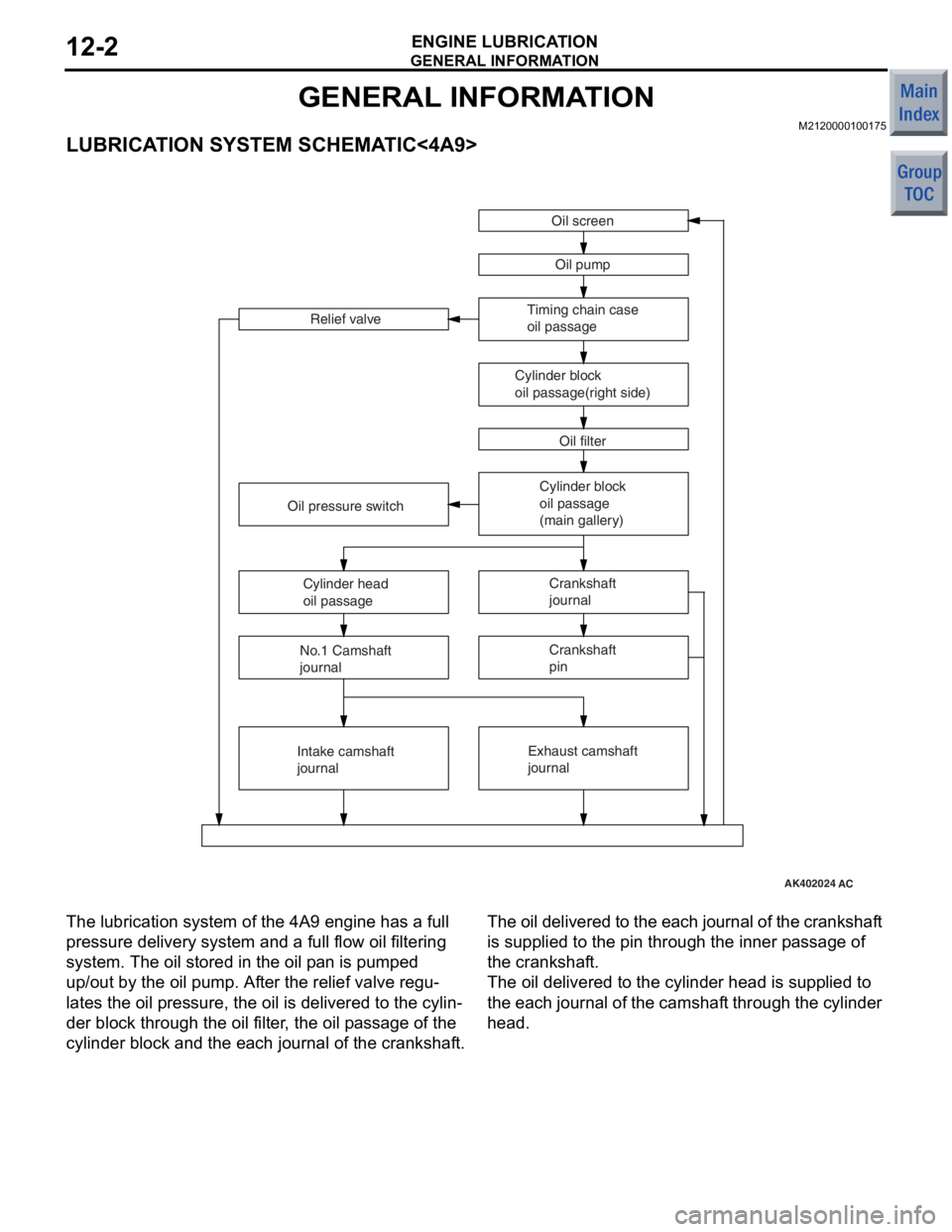
LUBRICATION SYSTEM SCHEMATIC<4A9>
AK402024AC
Oil screenOil pump
Timing chain case
oil passage
Cylinder block
oil passage(right side) Oil filter
Relief valve
Cylinder block
oil passage
(main gallery)Crankshaft
journal
Exhaust camshaft
journal
Oil pressure switch
Cylinder head
oil passage
No.1 Camshaft
journal
Intake camshaft
journal Crankshaft
pin
The lu
brication system of th e 4A9 en gine has a full
pressure de
livery system and a full flow oil filtering
system. The o
il stored in the oil p an is pumped
up/out
by th e oil pump. Af ter the relie f valve regu
-
lates the oil p r essure, th e oil is delivere d to th e cylin-
der block through the o il f ilte r , the o il p a ssag e of the
cylinde
r blo ck a nd the each jou r nal o f the crankshaf t.
The oil del ivered to the ea ch jo urnal of th e cranksh af t
is supplied
to the pin th rough the in ner p a ssage of
the crankshaf
t.
The oil delivered to the cylinder head is supplied t o
the ea
ch journa l of the camshaf t th rough the cylinde r
head.
Page 90 of 364
GENERAL INFORMATION
ENGINE LUBRICATION12-3
LUBRICATION SYSTEM SCHEMATIC<4G1>
AK402151AC
Oil screen
Oil pump
Oil filter
Relief valve
Cylinder block
oil passage
(main gallery)Crankshaft
journal
Exhaust camshaft
journal
Oil pan Oil pressure switch
Cylinder head
oil passage
No.1 Camshaft
journal
Intake camshaft
journal Crankshaft pin
PistonOil jet
Oil cooler
Turbo charger
Lash adjuster Cam
To correspond with the impr oved engine outp u t per-
formance b y emplo y ing the tu rboch a rger , the oil
cooler and
the oil jet are u s ed for 4GI engine.