2006 MERCEDES-BENZ SPRINTER transmission oil
[x] Cancel search: transmission oilPage 1878 of 2305
(14) Remove the transmission oil filter (1) and
o-ring from the electrohydraulic control unit.
(15) Clean the inside of the oil pan (3) of any
debris. Inspect the oil pan gasket (2) and replace if
necessary.
(16) Install a new oil filter (1) and o-ring into the
electrohydraulic control unit.
(17) Install the oil pan (3) and gasket (2) onto the
transmission.
(18) Install the oil pan bolts (5) and retainers (4).
Torque the bolts to 8 N´m (70 in.lbs.).
(19) Lower the vehicle and add 7.0 L (7.4 qts.) of
transmission fluid to the transmission.
(20) Check the oil level (Refer to 21 - TRANSMIS-
SION/AUTOMATIC - NAG1/FLUID AND FILTER -
STANDARD PROCEDURE - CHECK OIL LEVEL).
FREEWHEELING CLUTCH
DESCRIPTION
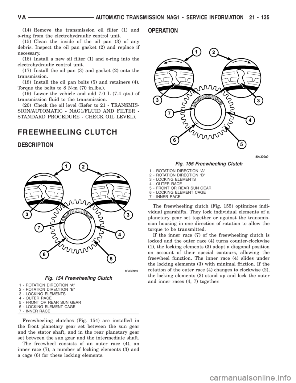
Freewheeling clutches (Fig. 154) are installed in
the front planetary gear set between the sun gear
and the stator shaft, and in the rear planetary gear
set between the sun gear and the intermediate shaft.
The freewheel consists of an outer race (4), an
inner race (7), a number of locking elements (3) and
a cage (6) for these locking elements.
OPERATION
The freewheeling clutch (Fig. 155) optimizes indi-
vidual gearshifts. They lock individual elements of a
planetary gear set together or against the transmis-
sion housing in one direction of rotation to allow the
torque to be transmitted.
If the inner race (7) of the freewheeling clutch is
locked and the outer race (4) turns counter-clockwise
(1), the locking elements (3) adopt a diagonal position
on account of their special contours, allowing the
freewheel function. The inner race (4) slides under
the locking elements (3) with minimal friction. If the
rotation of the outer race (4) changes to clockwise (2),
the locking elements (3) stand up and lock the outer
and inner races (4, 7) together.
Fig. 154 Freewheeling Clutch
1 - ROTATION DIRECTION ªA9
2 - ROTATION DIRECTION ªB9
3 - LOCKING ELEMENTS
4 - OUTER RACE
5 - FRONT OR REAR SUN GEAR
6 - LOCKING ELEMENT CAGE
7 - INNER RACE
Fig. 155 Freewheeling Clutch
1 - ROTATION DIRECTION ªA9
2 - ROTATION DIRECTION ªB9
3 - LOCKING ELEMENTS
4 - OUTER RACE
5 - FRONT OR REAR SUN GEAR
6 - LOCKING ELEMENT CAGE
7 - INNER RACE
VAAUTOMATIC TRANSMISSION NAG1 - SERVICE INFORMATION 21 - 135
Page 1885 of 2305
OPERATION
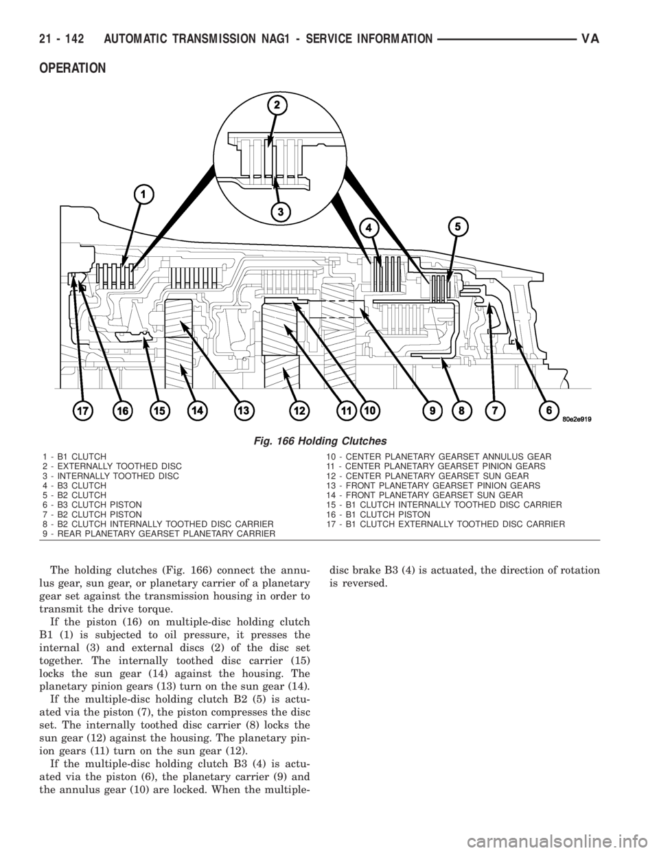
The holding clutches (Fig. 166) connect the annu-
lus gear, sun gear, or planetary carrier of a planetary
gear set against the transmission housing in order to
transmit the drive torque.
If the piston (16) on multiple-disc holding clutch
B1 (1) is subjected to oil pressure, it presses the
internal (3) and external discs (2) of the disc set
together. The internally toothed disc carrier (15)
locks the sun gear (14) against the housing. The
planetary pinion gears (13) turn on the sun gear (14).
If the multiple-disc holding clutch B2 (5) is actu-
ated via the piston (7), the piston compresses the disc
set. The internally toothed disc carrier (8) locks the
sun gear (12) against the housing. The planetary pin-
ion gears (11) turn on the sun gear (12).
If the multiple-disc holding clutch B3 (4) is actu-
ated via the piston (6), the planetary carrier (9) and
the annulus gear (10) are locked. When the multiple-disc brake B3 (4) is actuated, the direction of rotation
is reversed.
Fig. 166 Holding Clutches
1 - B1 CLUTCH 10 - CENTER PLANETARY GEARSET ANNULUS GEAR
2 - EXTERNALLY TOOTHED DISC 11 - CENTER PLANETARY GEARSET PINION GEARS
3 - INTERNALLY TOOTHED DISC 12 - CENTER PLANETARY GEARSET SUN GEAR
4 - B3 CLUTCH 13 - FRONT PLANETARY GEARSET PINION GEARS
5 - B2 CLUTCH 14 - FRONT PLANETARY GEARSET SUN GEAR
6 - B3 CLUTCH PISTON 15 - B1 CLUTCH INTERNALLY TOOTHED DISC CARRIER
7 - B2 CLUTCH PISTON 16 - B1 CLUTCH PISTON
8 - B2 CLUTCH INTERNALLY TOOTHED DISC CARRIER 17 - B1 CLUTCH EXTERNALLY TOOTHED DISC CARRIER
9 - REAR PLANETARY GEARSET PLANETARY CARRIER
21 - 142 AUTOMATIC TRANSMISSION NAG1 - SERVICE INFORMATIONVA
Page 1892 of 2305
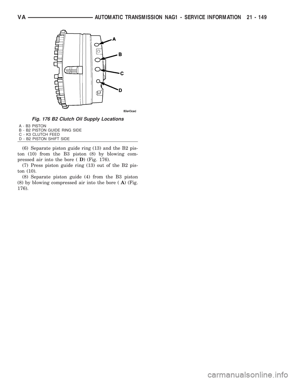
(6) Separate piston guide ring (13) and the B2 pis-
ton (10) from the B3 piston (8) by blowing com-
pressed air into the bore (D) (Fig. 176).
(7) Press piston guide ring (13) out of the B2 pis-
ton (10).
(8) Separate piston guide (4) from the B3 piston
(8) by blowing compressed air into the bore (A) (Fig.
176).
Fig. 176 B2 Clutch Oil Supply Locations
A - B3 PISTON
B - B2 PISTON GUIDE RING SIDE
C - K3 CLUTCH FEED
D - B2 PISTON SHIFT SIDE
VAAUTOMATIC TRANSMISSION NAG1 - SERVICE INFORMATION 21 - 149
Page 1897 of 2305
OPERATION
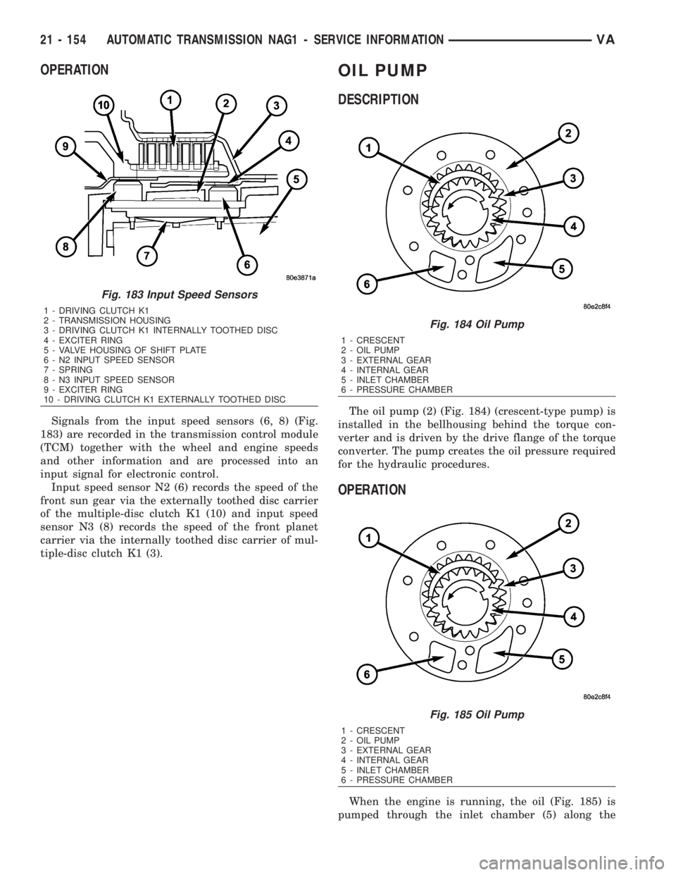
Signals from the input speed sensors (6, 8) (Fig.
183) are recorded in the transmission control module
(TCM) together with the wheel and engine speeds
and other information and are processed into an
input signal for electronic control.
Input speed sensor N2 (6) records the speed of the
front sun gear via the externally toothed disc carrier
of the multiple-disc clutch K1 (10) and input speed
sensor N3 (8) records the speed of the front planet
carrier via the internally toothed disc carrier of mul-
tiple-disc clutch K1 (3).
OIL PUMP
DESCRIPTION
The oil pump (2) (Fig. 184) (crescent-type pump) is
installed in the bellhousing behind the torque con-
verter and is driven by the drive flange of the torque
converter. The pump creates the oil pressure required
for the hydraulic procedures.
OPERATION
When the engine is running, the oil (Fig. 185) is
pumped through the inlet chamber (5) along the
Fig. 183 Input Speed Sensors
1 - DRIVING CLUTCH K1
2 - TRANSMISSION HOUSING
3 - DRIVING CLUTCH K1 INTERNALLY TOOTHED DISC
4 - EXCITER RING
5 - VALVE HOUSING OF SHIFT PLATE
6 - N2 INPUT SPEED SENSOR
7 - SPRING
8 - N3 INPUT SPEED SENSOR
9 - EXCITER RING
10 - DRIVING CLUTCH K1 EXTERNALLY TOOTHED DISC
Fig. 184 Oil Pump
1 - CRESCENT
2 - OIL PUMP
3 - EXTERNAL GEAR
4 - INTERNAL GEAR
5 - INLET CHAMBER
6 - PRESSURE CHAMBER
Fig. 185 Oil Pump
1 - CRESCENT
2 - OIL PUMP
3 - EXTERNAL GEAR
4 - INTERNAL GEAR
5 - INLET CHAMBER
6 - PRESSURE CHAMBER
21 - 154 AUTOMATIC TRANSMISSION NAG1 - SERVICE INFORMATIONVA
Page 1898 of 2305
upper and lower side of the crescent (1) to the pres-
sure chamber (6) of the housing. The meshing of the
teeth prevents oil flowing from the delivery side to
the intake side. An external gear (3) is eccentrically
mounted in the pump housing. The external gear is
driven by the internal gear (4) which is connected to
the torque converter hub.
DISASSEMBLY
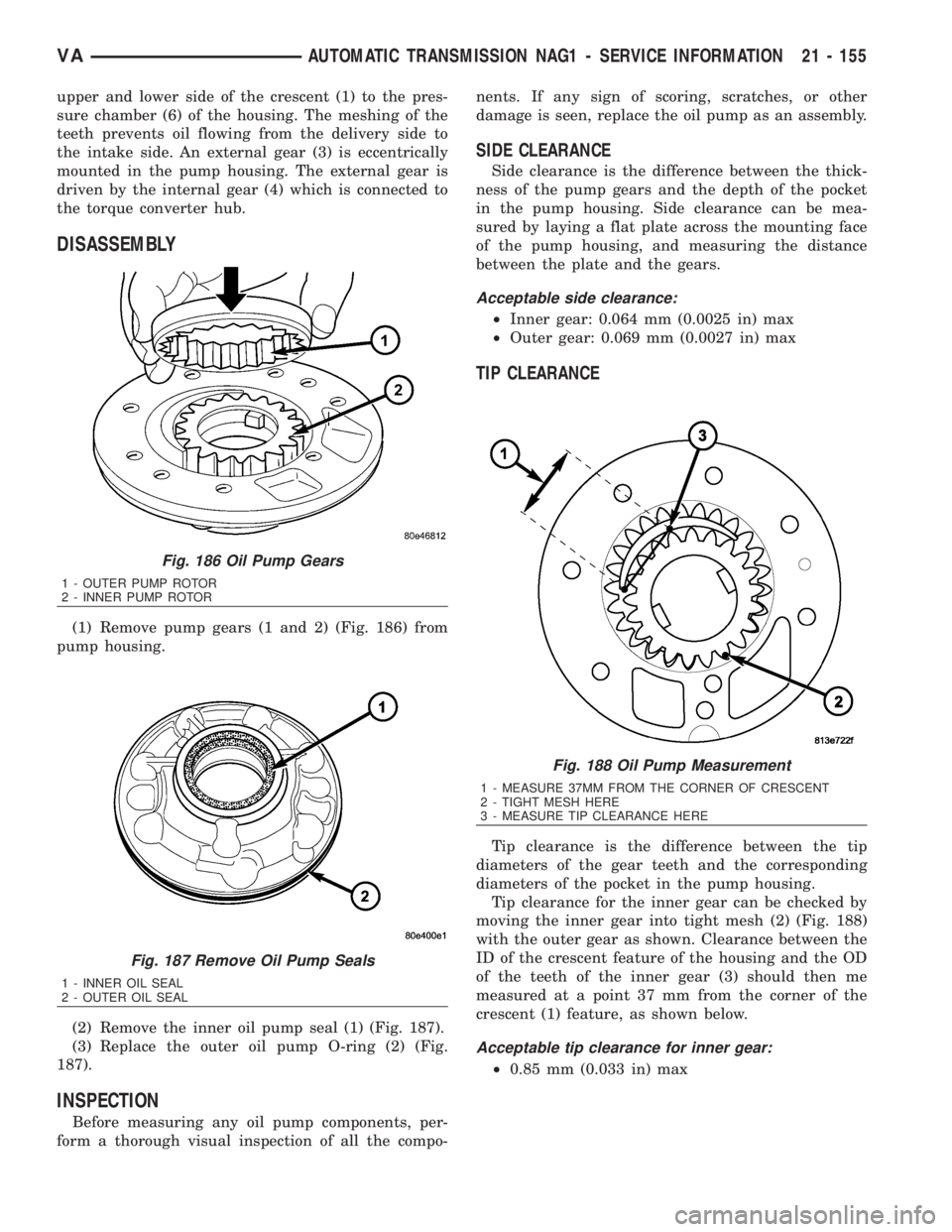
(1) Remove pump gears (1 and 2) (Fig. 186) from
pump housing.
(2) Remove the inner oil pump seal (1) (Fig. 187).
(3) Replace the outer oil pump O-ring (2) (Fig.
187).
INSPECTION
Before measuring any oil pump components, per-
form a thorough visual inspection of all the compo-nents. If any sign of scoring, scratches, or other
damage is seen, replace the oil pump as an assembly.
SIDE CLEARANCE
Side clearance is the difference between the thick-
ness of the pump gears and the depth of the pocket
in the pump housing. Side clearance can be mea-
sured by laying a flat plate across the mounting face
of the pump housing, and measuring the distance
between the plate and the gears.
Acceptable side clearance:
²Inner gear: 0.064 mm (0.0025 in) max
²Outer gear: 0.069 mm (0.0027 in) max
TIP CLEARANCE
Tip clearance is the difference between the tip
diameters of the gear teeth and the corresponding
diameters of the pocket in the pump housing.
Tip clearance for the inner gear can be checked by
moving the inner gear into tight mesh (2) (Fig. 188)
with the outer gear as shown. Clearance between the
ID of the crescent feature of the housing and the OD
of the teeth of the inner gear (3) should then me
measured at a point 37 mm from the corner of the
crescent (1) feature, as shown below.
Acceptable tip clearance for inner gear:
²0.85 mm (0.033 in) max
Fig. 186 Oil Pump Gears
1 - OUTER PUMP ROTOR
2 - INNER PUMP ROTOR
Fig. 187 Remove Oil Pump Seals
1 - INNER OIL SEAL
2 - OUTER OIL SEAL
Fig. 188 Oil Pump Measurement
1 - MEASURE 37MM FROM THE CORNER OF CRESCENT
2 - TIGHT MESH HERE
3 - MEASURE TIP CLEARANCE HERE
VAAUTOMATIC TRANSMISSION NAG1 - SERVICE INFORMATION 21 - 155
Page 1899 of 2305
ASSEMBLY
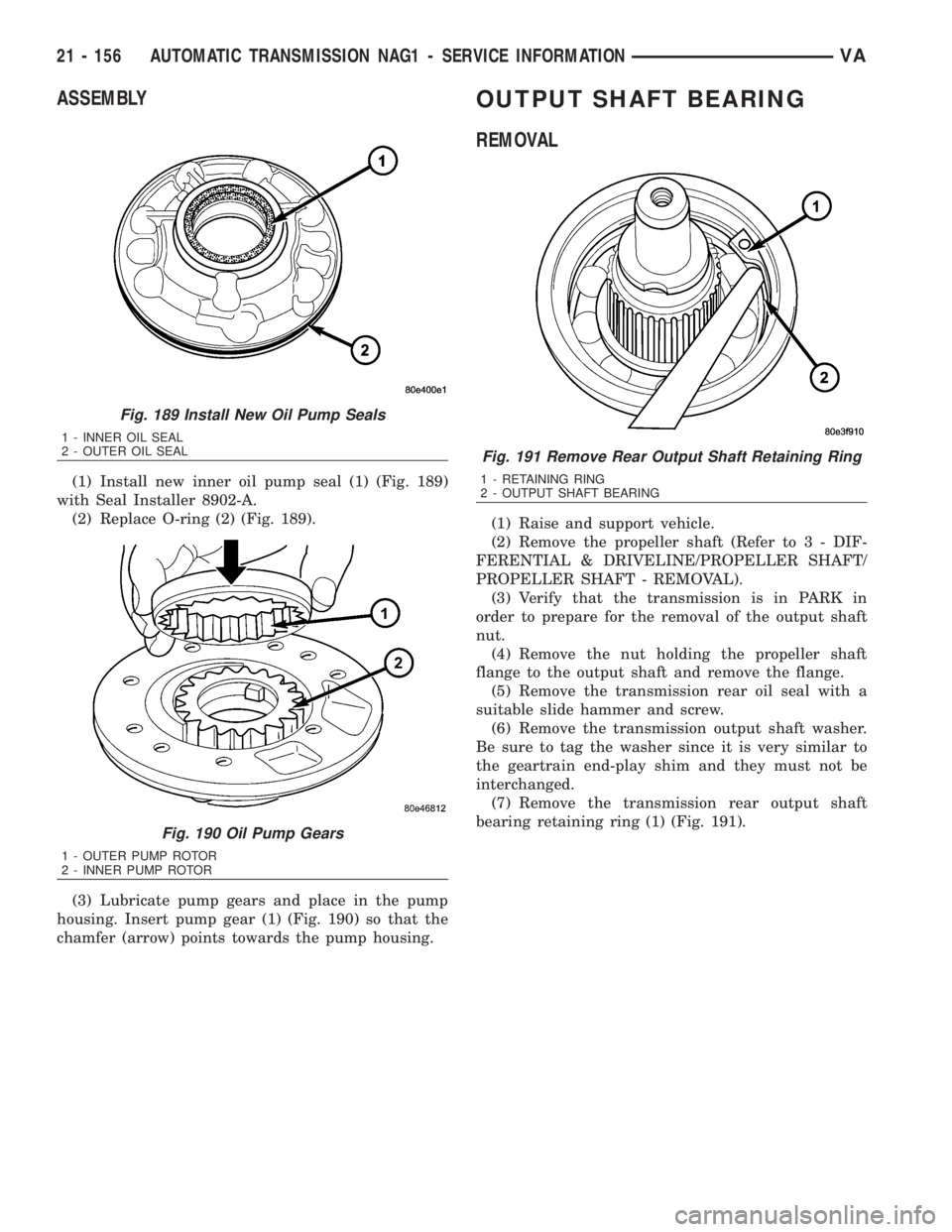
(1) Install new inner oil pump seal (1) (Fig. 189)
with Seal Installer 8902-A.
(2) Replace O-ring (2) (Fig. 189).
(3) Lubricate pump gears and place in the pump
housing. Insert pump gear (1) (Fig. 190) so that the
chamfer (arrow) points towards the pump housing.
OUTPUT SHAFT BEARING
REMOVAL
(1) Raise and support vehicle.
(2) Remove the propeller shaft (Refer to 3 - DIF-
FERENTIAL & DRIVELINE/PROPELLER SHAFT/
PROPELLER SHAFT - REMOVAL).
(3) Verify that the transmission is in PARK in
order to prepare for the removal of the output shaft
nut.
(4) Remove the nut holding the propeller shaft
flange to the output shaft and remove the flange.
(5) Remove the transmission rear oil seal with a
suitable slide hammer and screw.
(6) Remove the transmission output shaft washer.
Be sure to tag the washer since it is very similar to
the geartrain end-play shim and they must not be
interchanged.
(7) Remove the transmission rear output shaft
bearing retaining ring (1) (Fig. 191).
Fig. 189 Install New Oil Pump Seals
1 - INNER OIL SEAL
2 - OUTER OIL SEAL
Fig. 190 Oil Pump Gears
1 - OUTER PUMP ROTOR
2 - INNER PUMP ROTOR
Fig. 191 Remove Rear Output Shaft Retaining Ring
1 - RETAINING RING
2 - OUTPUT SHAFT BEARING
21 - 156 AUTOMATIC TRANSMISSION NAG1 - SERVICE INFORMATIONVA
Page 1914 of 2305
(5) Turn on ignition and apply brakes. Move selec-
tor lever back to position ªDº.
(6) Install the transmission shift cable onto the
ball knob at the SLA.
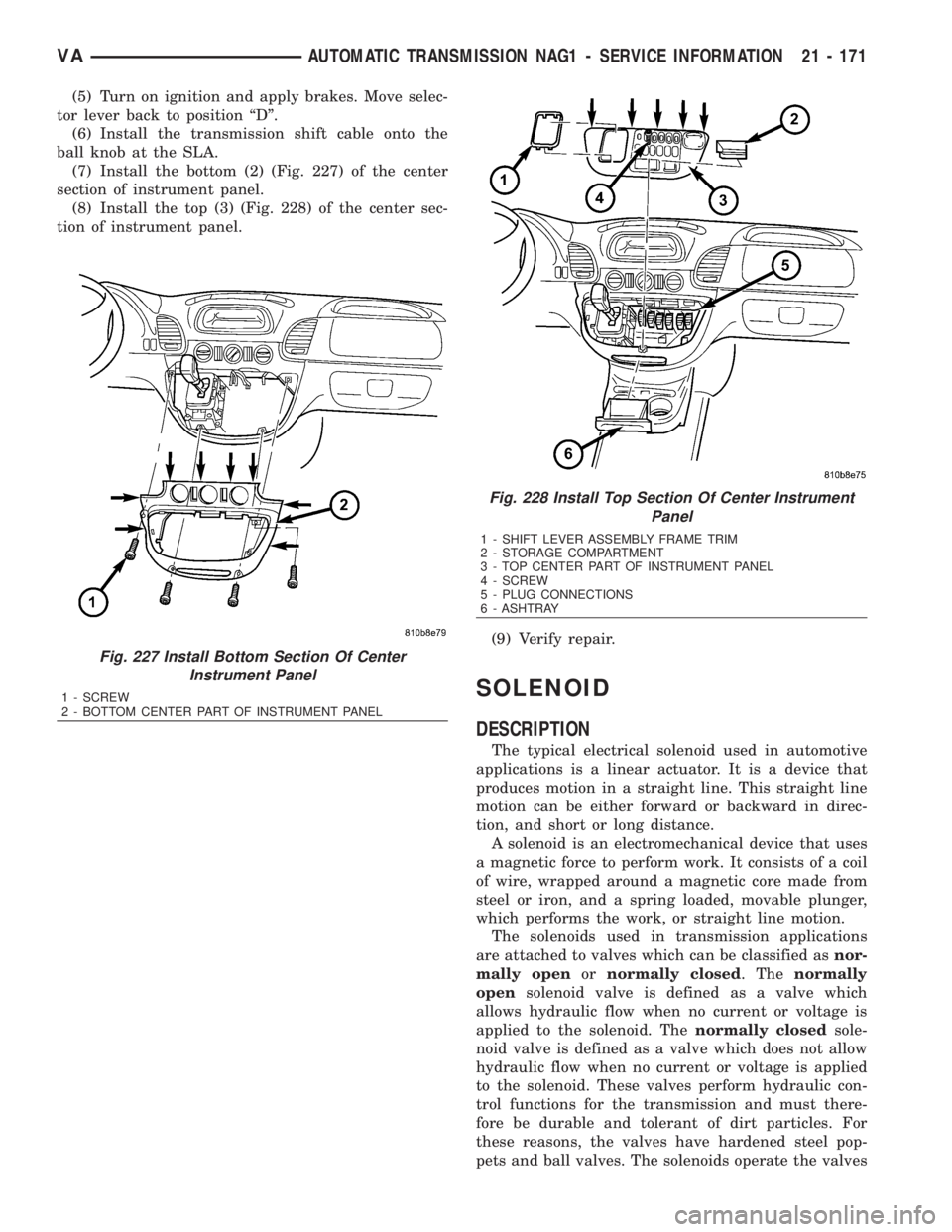
(7) Install the bottom (2) (Fig. 227) of the center
section of instrument panel.
(8) Install the top (3) (Fig. 228) of the center sec-
tion of instrument panel.
(9) Verify repair.
SOLENOID
DESCRIPTION
The typical electrical solenoid used in automotive
applications is a linear actuator. It is a device that
produces motion in a straight line. This straight line
motion can be either forward or backward in direc-
tion, and short or long distance.
A solenoid is an electromechanical device that uses
a magnetic force to perform work. It consists of a coil
of wire, wrapped around a magnetic core made from
steel or iron, and a spring loaded, movable plunger,
which performs the work, or straight line motion.
The solenoids used in transmission applications
are attached to valves which can be classified asnor-
mally openornormally closed. Thenormally
opensolenoid valve is defined as a valve which
allows hydraulic flow when no current or voltage is
applied to the solenoid. Thenormally closedsole-
noid valve is defined as a valve which does not allow
hydraulic flow when no current or voltage is applied
to the solenoid. These valves perform hydraulic con-
trol functions for the transmission and must there-
fore be durable and tolerant of dirt particles. For
these reasons, the valves have hardened steel pop-
pets and ball valves. The solenoids operate the valves
Fig. 227 Install Bottom Section Of Center
Instrument Panel
1 - SCREW
2 - BOTTOM CENTER PART OF INSTRUMENT PANEL
Fig. 228 Install Top Section Of Center Instrument
Panel
1 - SHIFT LEVER ASSEMBLY FRAME TRIM
2 - STORAGE COMPARTMENT
3 - TOP CENTER PART OF INSTRUMENT PANEL
4 - SCREW
5 - PLUG CONNECTIONS
6 - ASHTRAY
VAAUTOMATIC TRANSMISSION NAG1 - SERVICE INFORMATION 21 - 171
Page 1915 of 2305
directly, which means that the solenoids must have
very high outputs to close the valves against the siz-
able flow areas and line pressures found in current
transmissions. Fast response time is also necessary
to ensure accurate control of the transmission.
The strength of the magnetic field is the primary
force that determines the speed of operation in a par-
ticular solenoid design. A stronger magnetic field will
cause the plunger to move at a greater speed than a
weaker one. There are basically two ways to increase
the force of the magnetic field:
1. Increase the amount of current applied to the
coil or
2. Increase the number of turns of wire in the coil.
The most common practice is to increase the num-
ber of turns by using thin wire that can completely
fill the available space within the solenoid housing.
The strength of the spring and the length of the
plunger also contribute to the response speed possi-
ble by a particular solenoid design.
A solenoid can also be described by the method by
which it is controlled. Some of the possibilities
include variable force, pulse-width modulated, con-
stant ON, or duty cycle. The variable force and pulse-
width modulated versions utilize similar methods to
control the current flow through the solenoid to posi-
tion the solenoid plunger at a desired position some-
where between full ON and full OFF. The constant
ON and duty cycled versions control the voltage
across the solenoid to allow either full flow or no flow
through the solenoid's valve.UPSHIFT / DOWNSHIFT SOLENOID VALVES
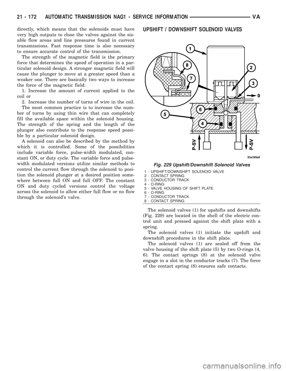
The solenoid valves (1) for upshifts and downshifts
(Fig. 229) are located in the shell of the electric con-
trol unit and pressed against the shift plate with a
spring.
The solenoid valves (1) initiate the upshift and
downshift procedures in the shift plate.
The solenoid valves (1) are sealed off from the
valve housing of the shift plate (5) by two O-rings (4,
6). The contact springs (8) at the solenoid valve
engage in a slot in the conductor tracks (7). The force
of the contact spring (8) ensures safe contacts.
Fig. 229 Upshift/Downshift Solenoid Valves
1 - UPSHIFT/DOWNSHIFT SOLENOID VALVE
2 - CONTACT SPRING
3 - CONDUCTOR TRACK
4 - O-RING
5 - VALVE HOUSING OF SHIFT PLATE
6 - O-RING
7 - CONDUCTOR TRACK
8 - CONTACT SPRING
21 - 172 AUTOMATIC TRANSMISSION NAG1 - SERVICE INFORMATIONVA