Page 373 of 2305
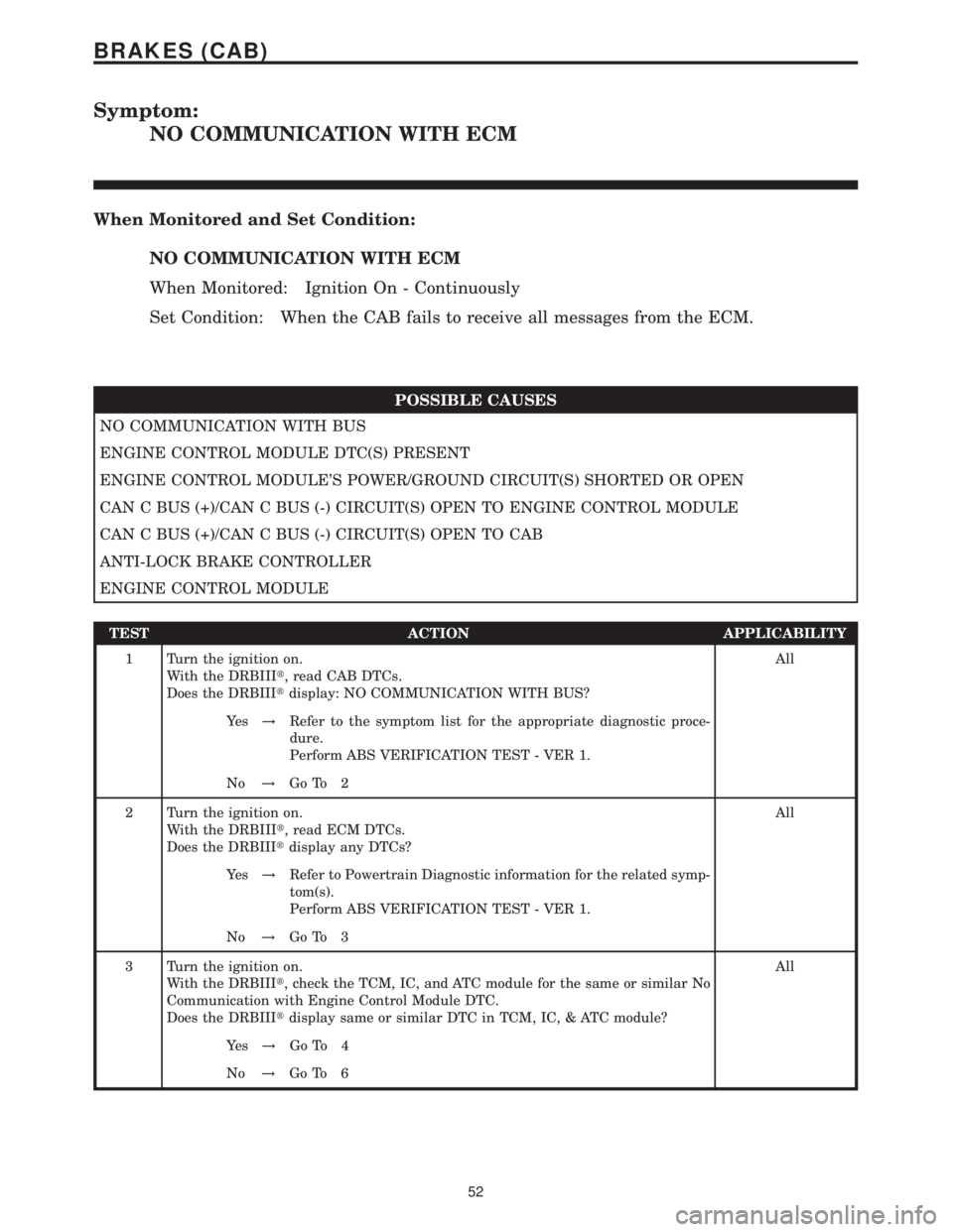
Symptom:
NO COMMUNICATION WITH ECM
When Monitored and Set Condition:
NO COMMUNICATION WITH ECM
When Monitored: Ignition On - Continuously
Set Condition: When the CAB fails to receive all messages from the ECM.
POSSIBLE CAUSES
NO COMMUNICATION WITH BUS
ENGINE CONTROL MODULE DTC(S) PRESENT
ENGINE CONTROL MODULE'S POWER/GROUND CIRCUIT(S) SHORTED OR OPEN
CAN C BUS (+)/CAN C BUS (-) CIRCUIT(S) OPEN TO ENGINE CONTROL MODULE
CAN C BUS (+)/CAN C BUS (-) CIRCUIT(S) OPEN TO CAB
ANTI-LOCK BRAKE CONTROLLER
ENGINE CONTROL MODULE
TEST ACTION APPLICABILITY
1 Turn the ignition on.
With the DRBIIIt, read CAB DTCs.
Does the DRBIIItdisplay: NO COMMUNICATION WITH BUS?All
Ye s!Refer to the symptom list for the appropriate diagnostic proce-
dure.
Perform ABS VERIFICATION TEST - VER 1.
No!Go To 2
2 Turn the ignition on.
With the DRBIIIt, read ECM DTCs.
Does the DRBIIItdisplay any DTCs?All
Ye s!Refer to Powertrain Diagnostic information for the related symp-
tom(s).
Perform ABS VERIFICATION TEST - VER 1.
No!Go To 3
3 Turn the ignition on.
With the DRBIIIt, check the TCM, IC, and ATC module for the same or similar No
Communication with Engine Control Module DTC.
Does the DRBIIItdisplay same or similar DTC in TCM, IC, & ATC module?All
Ye s!Go To 4
No!Go To 6
52
BRAKES (CAB)
Page 374 of 2305
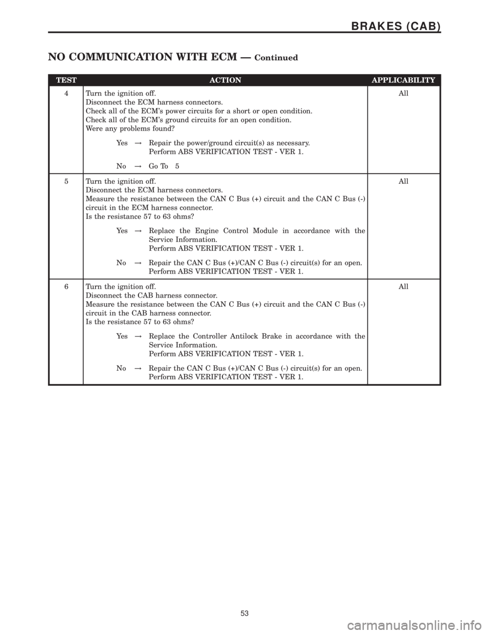
TEST ACTION APPLICABILITY
4 Turn the ignition off.
Disconnect the ECM harness connectors.
Check all of the ECM's power circuits for a short or open condition.
Check all of the ECM's ground circuits for an open condition.
Were any problems found?All
Ye s!Repair the power/ground circuit(s) as necessary.
Perform ABS VERIFICATION TEST - VER 1.
No!Go To 5
5 Turn the ignition off.
Disconnect the ECM harness connectors.
Measure the resistance between the CAN C Bus (+) circuit and the CAN C Bus (-)
circuit in the ECM harness connector.
Is the resistance 57 to 63 ohms?All
Ye s!Replace the Engine Control Module in accordance with the
Service Information.
Perform ABS VERIFICATION TEST - VER 1.
No!Repair the CAN C Bus (+)/CAN C Bus (-) circuit(s) for an open.
Perform ABS VERIFICATION TEST - VER 1.
6 Turn the ignition off.
Disconnect the CAB harness connector.
Measure the resistance between the CAN C Bus (+) circuit and the CAN C Bus (-)
circuit in the CAB harness connector.
Is the resistance 57 to 63 ohms?All
Ye s!Replace the Controller Antilock Brake in accordance with the
Service Information.
Perform ABS VERIFICATION TEST - VER 1.
No!Repair the CAN C Bus (+)/CAN C Bus (-) circuit(s) for an open.
Perform ABS VERIFICATION TEST - VER 1.
53
BRAKES (CAB)
NO COMMUNICATION WITH ECM ÐContinued
Page 381 of 2305
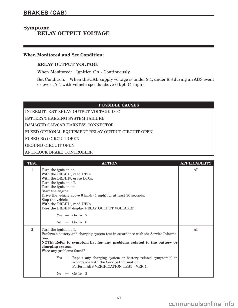
Symptom:
RELAY OUTPUT VOLTAGE
When Monitored and Set Condition:
RELAY OUTPUT VOLTAGE
When Monitored: Ignition On - Continuously.
Set Condition: When the CAB supply voltage is under 9.4, under 8.8 during an ABS event
or over 17.4 with vehicle speeds above 6 kph (4 mph).
POSSIBLE CAUSES
INTERMITTENT RELAY OUTPUT VOLTAGE DTC
BATTERY/CHARGING SYSTEM FAILURE
DAMAGED CAB/CAB HARNESS CONNECTOR
FUSED OPTIONAL EQUIPMENT RELAY OUTPUT CIRCUIT OPEN
FUSED B(+) CIRCUIT OPEN
GROUND CIRCUIT OPEN
ANTI-LOCK BRAKE CONTROLLER
TEST ACTION APPLICABILITY
1 Turn the ignition on.
With the DRBIIIt, read DTCs.
With the DRBIIIt, erase DTCs.
Turn the ignition off.
Turn the ignition on.
Start the engine.
Drive the vehicle above 6 km/h (4 mph) for at least 30 seconds.
Stop the vehicle.
With the DRBIIIt, read DTCs.
Does the DRBIIItdisplay RELAY OUTPUT VOLTAGE?All
Ye s!Go To 2
No!Go To 8
2 Turn the ignition off.
Perform a battery and charging system test in accordance with the Service Informa-
tion.
NOTE: Refer to symptom list for any problems related to the battery or
charging system.
Were any problems found?All
Ye s!Repair any charging system or battery related symptom(s) in
accordance with the Service Information.
Perform ABS VERIFICATION TEST - VER 1.
No!Go To 3
60
BRAKES (CAB)
Page 382 of 2305

TEST ACTION APPLICABILITY
3 Turn the ignition off.
Disconnect the CAB harness connector.
Inspect the CAB/CAB harness connector for damage.
Is there any broken, bent, pushed out, corroded or spread terminals?All
Ye s!Repair as necessary.
Perform ABS VERIFICATION TEST - VER 1.
No!Go To 4
4 Turn the ignition off.
Turn the ignition on.
With the DRBIIItin Sensors, read the Relay Output voltage.
Start the engine.
With the DRBIIItin Sensors, read the Relay Output voltage.
Select the Relay Output voltage that was displayed on the DRBIIIt.All
Voltage below 9.4 volts.
Go To 5
Voltage above 17.4 volts.
Go To 7
Voltage between 9.4 and 17.4 volts.
Go To 8
5 Turn the ignition off.
Disconnect the CAB harness connector.
Start the engine.
Allow the engine to idle.
WARNING: WHEN THE ENGINE IS OPERATING, DO NOT STAND IN A
DIRECT LINE WITH THE FAN. DO NOT PUT YOUR HANDS NEAR THE
PULLEYS, BELTS OR FAN. DO NOT WEAR LOOSE CLOTHING.
Measure the voltage of the Fused Optional Equipment Relay Output circuit in the
CAB harness connector.
Raise the engine speed above 2,000 RPM's.
Measure the voltage of the Fused Optional Equipment Relay Output circuit in the
CAB harness connector.
Is the voltage less than 9.4 volts?All
Ye s!Repair the Fused Optional Equipment Relay Output circuit for an
open.
Perform ABS VERIFICATION TEST - VER 1.
No!Go To 6
61
BRAKES (CAB)
RELAY OUTPUT VOLTAGE ÐContinued
Page 383 of 2305
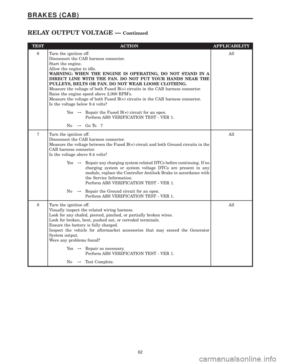
TEST ACTION APPLICABILITY
6 Turn the ignition off.
Disconnect the CAB harness connector.
Start the engine.
Allow the engine to idle.
WARNING: WHEN THE ENGINE IS OPERATING, DO NOT STAND IN A
DIRECT LINE WITH THE FAN. DO NOT PUT YOUR HANDS NEAR THE
PULLEYS, BELTS OR FAN. DO NOT WEAR LOOSE CLOTHING.
Measure the voltage of both Fused B(+) circuits in the CAB harness connector.
Raise the engine speed above 2,000 RPM's.
Measure the voltage of both Fused B(+) circuits in the CAB harness connector.
Is the voltage below 9.4 volts?All
Ye s!Repair the Fused B(+) circuit for an open.
Perform ABS VERIFICATION TEST - VER 1.
No!Go To 7
7 Turn the ignition off.
Disconnect the CAB harness connector.
Measure the voltage between the Fused B(+) circuit and both Ground circuits in the
CAB harness connector.
Is the voltage above 9.4 volts?All
Ye s!Repair any charging system related DTCs before continuing. If no
charging system or system voltage DTCs are present in any
module, replace the Controller Antilock Brake in accordance with
the Service Information.
Perform ABS VERIFICATION TEST - VER 1.
No!Repair the Ground circuit for an open.
Perform ABS VERIFICATION TEST - VER 1.
8 Turn the ignition off.
Visually inspect the related wiring harness.
Look for any chafed, pierced, pinched, or partially broken wires.
Look for broken, bent, pushed out, or corroded terminals.
Ensure the battery is fully charged.
Inspect the vehicle for aftermarket accessories that may exceed the Generator
System output.
Were any problems found?All
Ye s!Repair as necessary.
Perform ABS VERIFICATION TEST - VER 1.
No!Test Complete.
62
BRAKES (CAB)
RELAY OUTPUT VOLTAGE ÐContinued
Page 396 of 2305
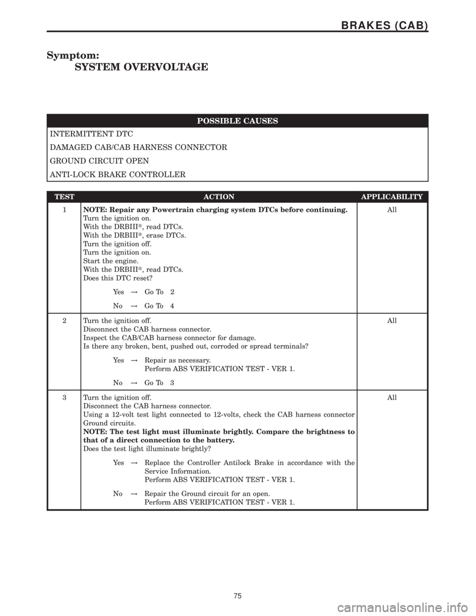
Symptom:
SYSTEM OVERVOLTAGE
POSSIBLE CAUSES
INTERMITTENT DTC
DAMAGED CAB/CAB HARNESS CONNECTOR
GROUND CIRCUIT OPEN
ANTI-LOCK BRAKE CONTROLLER
TEST ACTION APPLICABILITY
1NOTE: Repair any Powertrain charging system DTCs before continuing.
Turn the ignition on.
With the DRBIIIt, read DTCs.
With the DRBIIIt, erase DTCs.
Turn the ignition off.
Turn the ignition on.
Start the engine.
With the DRBIIIt, read DTCs.
Does this DTC reset?All
Ye s!Go To 2
No!Go To 4
2 Turn the ignition off.
Disconnect the CAB harness connector.
Inspect the CAB/CAB harness connector for damage.
Is there any broken, bent, pushed out, corroded or spread terminals?All
Ye s!Repair as necessary.
Perform ABS VERIFICATION TEST - VER 1.
No!Go To 3
3 Turn the ignition off.
Disconnect the CAB harness connector.
Using a 12-volt test light connected to 12-volts, check the CAB harness connector
Ground circuits.
NOTE: The test light must illuminate brightly. Compare the brightness to
that of a direct connection to the battery.
Does the test light illuminate brightly?All
Ye s!Replace the Controller Antilock Brake in accordance with the
Service Information.
Perform ABS VERIFICATION TEST - VER 1.
No!Repair the Ground circuit for an open.
Perform ABS VERIFICATION TEST - VER 1.
75
BRAKES (CAB)
Page 398 of 2305
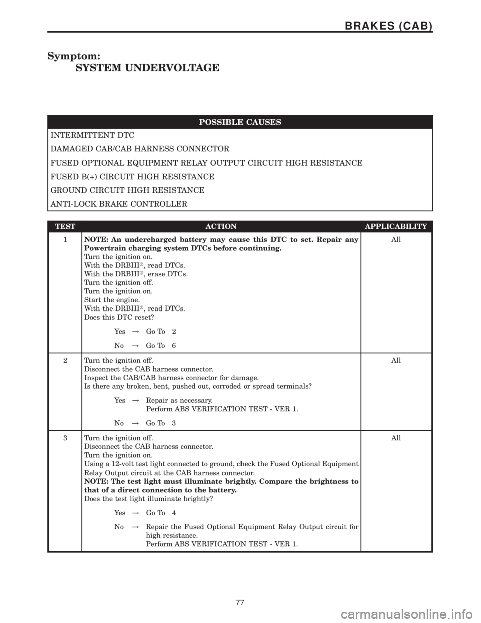
Symptom:
SYSTEM UNDERVOLTAGE
POSSIBLE CAUSES
INTERMITTENT DTC
DAMAGED CAB/CAB HARNESS CONNECTOR
FUSED OPTIONAL EQUIPMENT RELAY OUTPUT CIRCUIT HIGH RESISTANCE
FUSED B(+) CIRCUIT HIGH RESISTANCE
GROUND CIRCUIT HIGH RESISTANCE
ANTI-LOCK BRAKE CONTROLLER
TEST ACTION APPLICABILITY
1NOTE: An undercharged battery may cause this DTC to set. Repair any
Powertrain charging system DTCs before continuing.
Turn the ignition on.
With the DRBIIIt, read DTCs.
With the DRBIIIt, erase DTCs.
Turn the ignition off.
Turn the ignition on.
Start the engine.
With the DRBIIIt, read DTCs.
Does this DTC reset?All
Ye s!Go To 2
No!Go To 6
2 Turn the ignition off.
Disconnect the CAB harness connector.
Inspect the CAB/CAB harness connector for damage.
Is there any broken, bent, pushed out, corroded or spread terminals?All
Ye s!Repair as necessary.
Perform ABS VERIFICATION TEST - VER 1.
No!Go To 3
3 Turn the ignition off.
Disconnect the CAB harness connector.
Turn the ignition on.
Using a 12-volt test light connected to ground, check the Fused Optional Equipment
Relay Output circuit at the CAB harness connector.
NOTE: The test light must illuminate brightly. Compare the brightness to
that of a direct connection to the battery.
Does the test light illuminate brightly?All
Ye s!Go To 4
No!Repair the Fused Optional Equipment Relay Output circuit for
high resistance.
Perform ABS VERIFICATION TEST - VER 1.
77
BRAKES (CAB)
Page 400 of 2305

Verification Tests
ABS VERIFICATION TEST - VER 1 APPLICABILITY
1. Turn the ignition off.
2. Connect all previously disconnected components and connectors.
3. Ensure all accessories are turned off and the battery is fully charged.
4. Ensure that the Ignition is on, and with the DRBIII, erase all Diagnostic Trouble Codes from
ALL modules. Start the engine and allow it to run for 2 minutes and fully operate the system
that was malfunctioning.
5. Turn the ignition off and wait 5 seconds. Turn the ignition on and using the DRBIII, read
DTC's from ALL modules.
6. If any Diagnostic Trouble Codes are present, return to Symptom list and troubleshoot new
or recurring symptom.
7. NOTE: If the CAB/HCU was replaced, ensure the CAB has been initialized
8. NOTE: If the SKREEM or ECM was replaced, refer to the service information for
proper programming procedures.
9. NOTE: For Sensor Circuit/Signal and Pump Motor faults, the CAB must sense all 4
wheels at 12 km/h (8 mph) before it will extinguish the ABS Indicator.
10. If there are no DTC's present after turning ignition on, road test the vehicle for at least 5
minutes. Perform several antilock braking stops.
11. CAUTION: Ensure braking capability is available before road testing.
12. Again, with the DRBIIItread DTC's. If any DTC's are present, return to Symptom list.
13. If there are no Diagnostic Trouble Codes (DTC's) present, and the customer's concern can
no longer be duplicated, the repair is complete.
Are any DTC's present or is the original concern still present?All
Ye s!Repair is not complete, refer to appropriate symptom.
No!Repair is complete.
79
VERIFICATION TESTS