2006 MERCEDES-BENZ SPRINTER check oil
[x] Cancel search: check oilPage 1877 of 2305
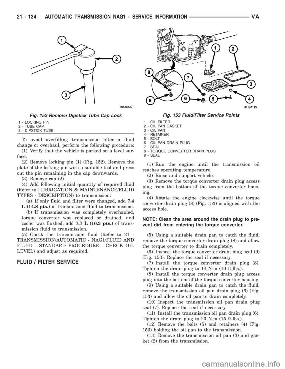
To avoid overfilling transmission after a fluid
change or overhaul, perform the following procedure:
(1) Verify that the vehicle is parked on a level sur-
face.
(2) Remove locking pin (1) (Fig. 152). Remove the
plate of the locking pin with a suitable tool and press
out the pin remaining in the cap downwards.
(3) Remove cap (2).
(4) Add following initial quantity of required fluid
(Refer to LUBRICATION & MAINTENANCE/FLUID
TYPES - DESCRIPTION) to transmission:
(a) If only fluid and filter were changed, add7.4
L (14.8 pts.)of transmission fluid to transmission.
(b) If transmission was completely overhauled,
torque converter was replaced or drained, and
cooler was flushed, add7.7 L (16.3 pts.)of trans-
mission fluid to transmission.
(5) Check the transmission fluid (Refer to 21 -
TRANSMISSION/AUTOMATIC - NAG1/FLUID AND
FLUID - STANDARD PROCEDURE - CHECK OIL
LEVEL) and adjust as required.
FLUID / FILTER SERVICE
(1) Run the engine until the transmission oil
reaches operating temperature.
(2) Raise and support vehicle.
(3) Remove the torque converter drain plug access
plug from the bottom of the torque converter hous-
ing.
(4) Rotate the engine clockwise until the torque
converter drain plug (8) (Fig. 153) is aligned with the
access hole.
NOTE: Clean the area around the drain plug to pre-
vent dirt from entering the torque converter.
(5) Using a suitable drain pan to catch the fluid,
remove the torque converter drain plug (8) and allow
the torque converter to drain completely.
(6) Inspect the torque converter drain plug seal (9)
(Fig. 153). Replace the seal if necessary.
(7) Install the torque converter drain plug (8).
Tighten the drain plug to 14 N´m (10 ft.lbs.).
(8) Install the torque converter drain plug access
plug into the bottom of the torque converter housing.
(9) Using a suitable drain pan to catch the fluid,
remove the transmission oil pan drain plug (6) (Fig.
153) and allow the oil pan to drain completely.
(10) Inspect the transmission oil pan drain plug
seal (7). Replace the seal if necessary.
(11) Install the transmission oil pan drain plug (6).
Tighten the drain plug to 20 N´m (15 ft.lbs.).
(12) Remove the bolts (5) and retainers (4) (Fig.
153) holding the oil pan to the transmission.
(13) Remove the transmission oil pan (3) and gas-
ket (2) from the transmission.
Fig. 152 Remove Dipstick Tube Cap Lock
1 - LOCKING PIN
2 - TUBE CAP
3 - DIPSTICK TUBE
Fig. 153 Fluid/Filter Service Points
1 - OIL FILTER
2 - OIL PAN GASKET
3 - OIL PAN
4 - RETAINER
5 - BOLT
6 - OIL PAN DRAIN PLUG
7 - SEAL
8 - TORQUE CONVERTER DRAIN PLUG
9 - SEAL
21 - 134 AUTOMATIC TRANSMISSION NAG1 - SERVICE INFORMATIONVA
Page 1878 of 2305
(14) Remove the transmission oil filter (1) and
o-ring from the electrohydraulic control unit.
(15) Clean the inside of the oil pan (3) of any
debris. Inspect the oil pan gasket (2) and replace if
necessary.
(16) Install a new oil filter (1) and o-ring into the
electrohydraulic control unit.
(17) Install the oil pan (3) and gasket (2) onto the
transmission.
(18) Install the oil pan bolts (5) and retainers (4).
Torque the bolts to 8 N´m (70 in.lbs.).
(19) Lower the vehicle and add 7.0 L (7.4 qts.) of
transmission fluid to the transmission.
(20) Check the oil level (Refer to 21 - TRANSMIS-
SION/AUTOMATIC - NAG1/FLUID AND FILTER -
STANDARD PROCEDURE - CHECK OIL LEVEL).
FREEWHEELING CLUTCH
DESCRIPTION
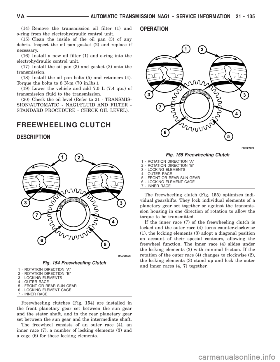
Freewheeling clutches (Fig. 154) are installed in
the front planetary gear set between the sun gear
and the stator shaft, and in the rear planetary gear
set between the sun gear and the intermediate shaft.
The freewheel consists of an outer race (4), an
inner race (7), a number of locking elements (3) and
a cage (6) for these locking elements.
OPERATION
The freewheeling clutch (Fig. 155) optimizes indi-
vidual gearshifts. They lock individual elements of a
planetary gear set together or against the transmis-
sion housing in one direction of rotation to allow the
torque to be transmitted.
If the inner race (7) of the freewheeling clutch is
locked and the outer race (4) turns counter-clockwise
(1), the locking elements (3) adopt a diagonal position
on account of their special contours, allowing the
freewheel function. The inner race (4) slides under
the locking elements (3) with minimal friction. If the
rotation of the outer race (4) changes to clockwise (2),
the locking elements (3) stand up and lock the outer
and inner races (4, 7) together.
Fig. 154 Freewheeling Clutch
1 - ROTATION DIRECTION ªA9
2 - ROTATION DIRECTION ªB9
3 - LOCKING ELEMENTS
4 - OUTER RACE
5 - FRONT OR REAR SUN GEAR
6 - LOCKING ELEMENT CAGE
7 - INNER RACE
Fig. 155 Freewheeling Clutch
1 - ROTATION DIRECTION ªA9
2 - ROTATION DIRECTION ªB9
3 - LOCKING ELEMENTS
4 - OUTER RACE
5 - FRONT OR REAR SUN GEAR
6 - LOCKING ELEMENT CAGE
7 - INNER RACE
VAAUTOMATIC TRANSMISSION NAG1 - SERVICE INFORMATION 21 - 135
Page 1898 of 2305
upper and lower side of the crescent (1) to the pres-
sure chamber (6) of the housing. The meshing of the
teeth prevents oil flowing from the delivery side to
the intake side. An external gear (3) is eccentrically
mounted in the pump housing. The external gear is
driven by the internal gear (4) which is connected to
the torque converter hub.
DISASSEMBLY
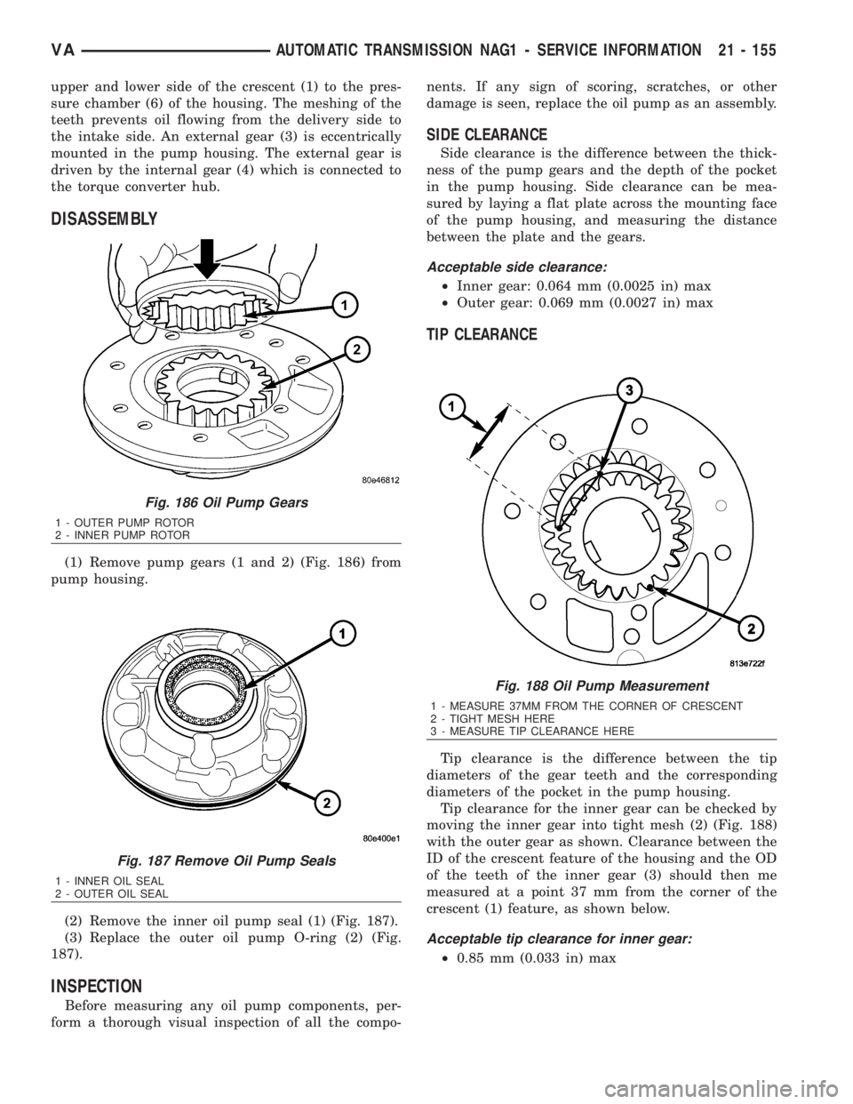
(1) Remove pump gears (1 and 2) (Fig. 186) from
pump housing.
(2) Remove the inner oil pump seal (1) (Fig. 187).
(3) Replace the outer oil pump O-ring (2) (Fig.
187).
INSPECTION
Before measuring any oil pump components, per-
form a thorough visual inspection of all the compo-nents. If any sign of scoring, scratches, or other
damage is seen, replace the oil pump as an assembly.
SIDE CLEARANCE
Side clearance is the difference between the thick-
ness of the pump gears and the depth of the pocket
in the pump housing. Side clearance can be mea-
sured by laying a flat plate across the mounting face
of the pump housing, and measuring the distance
between the plate and the gears.
Acceptable side clearance:
²Inner gear: 0.064 mm (0.0025 in) max
²Outer gear: 0.069 mm (0.0027 in) max
TIP CLEARANCE
Tip clearance is the difference between the tip
diameters of the gear teeth and the corresponding
diameters of the pocket in the pump housing.
Tip clearance for the inner gear can be checked by
moving the inner gear into tight mesh (2) (Fig. 188)
with the outer gear as shown. Clearance between the
ID of the crescent feature of the housing and the OD
of the teeth of the inner gear (3) should then me
measured at a point 37 mm from the corner of the
crescent (1) feature, as shown below.
Acceptable tip clearance for inner gear:
²0.85 mm (0.033 in) max
Fig. 186 Oil Pump Gears
1 - OUTER PUMP ROTOR
2 - INNER PUMP ROTOR
Fig. 187 Remove Oil Pump Seals
1 - INNER OIL SEAL
2 - OUTER OIL SEAL
Fig. 188 Oil Pump Measurement
1 - MEASURE 37MM FROM THE CORNER OF CRESCENT
2 - TIGHT MESH HERE
3 - MEASURE TIP CLEARANCE HERE
VAAUTOMATIC TRANSMISSION NAG1 - SERVICE INFORMATION 21 - 155
Page 1927 of 2305
INSTALLATION
Check converter hub and drive flats for sharp
edges, burrs, scratches, or nicks. Polish the hub and
flats with 320/400 grit paper or crocus cloth if neces-
sary. The hub must be smooth to avoid damaging the
pump seal at installation.
(1) Lubricate oil pump seal lip with transmission
fluid.
(2)
Place torque converter in position on transmission.
CAUTION: Do not damage oil pump seal or con-
verter hub while inserting torque converter into the
front of the transmission.
(3) Align torque converter to oil pump seal open-
ing.
(4) Insert torque converter hub into oil pump.
(5) While pushing torque converter inward, rotate
converter until converter is fully seated in the oil
pump gears.
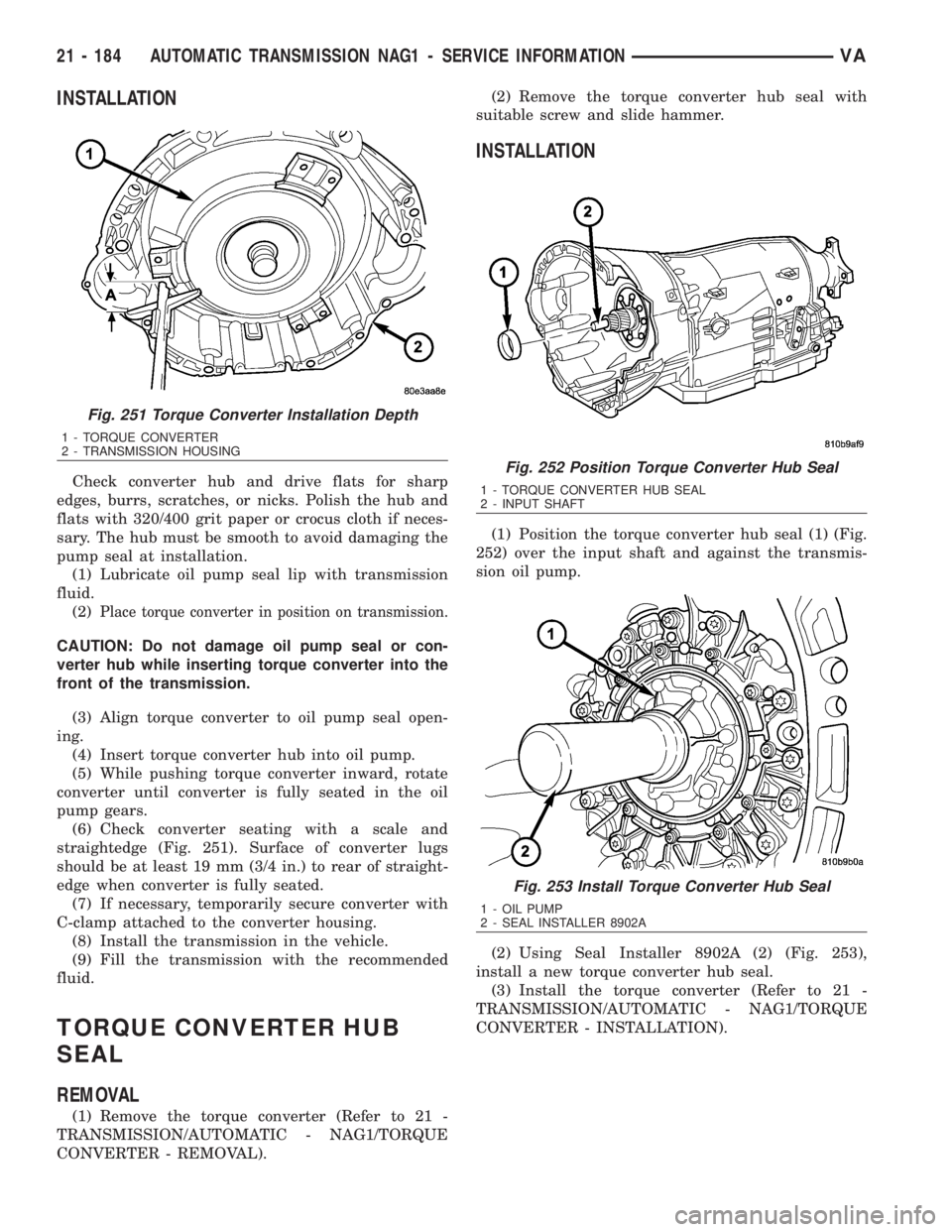
(6) Check converter seating with a scale and
straightedge (Fig. 251). Surface of converter lugs
should be at least 19 mm (3/4 in.) to rear of straight-
edge when converter is fully seated.
(7) If necessary, temporarily secure converter with
C-clamp attached to the converter housing.
(8) Install the transmission in the vehicle.
(9) Fill the transmission with the recommended
fluid.
TORQUE CONVERTER HUB
SEAL
REMOVAL
(1) Remove the torque converter (Refer to 21 -
TRANSMISSION/AUTOMATIC - NAG1/TORQUE
CONVERTER - REMOVAL).(2) Remove the torque converter hub seal with
suitable screw and slide hammer.
INSTALLATION
(1) Position the torque converter hub seal (1) (Fig.
252) over the input shaft and against the transmis-
sion oil pump.
(2) Using Seal Installer 8902A (2) (Fig. 253),
install a new torque converter hub seal.
(3) Install the torque converter (Refer to 21 -
TRANSMISSION/AUTOMATIC - NAG1/TORQUE
CONVERTER - INSTALLATION).
Fig. 251 Torque Converter Installation Depth
1 - TORQUE CONVERTER
2 - TRANSMISSION HOUSING
Fig. 252 Position Torque Converter Hub Seal
1 - TORQUE CONVERTER HUB SEAL
2 - INPUT SHAFT
Fig. 253 Install Torque Converter Hub Seal
1 - OIL PUMP
2 - SEAL INSTALLER 8902A
21 - 184 AUTOMATIC TRANSMISSION NAG1 - SERVICE INFORMATIONVA
Page 1954 of 2305
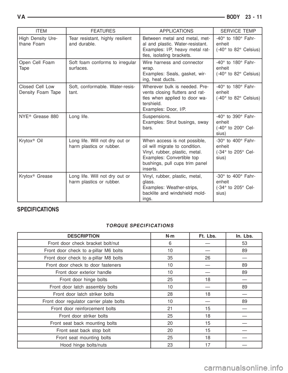
ITEM FEATURES APPLICATIONS SERVICE TEMP
High Density Ure-
thane FoamTear resistant, highly resilient
and durable.Between metal and metal, met-
al and plastic. Water-resistant.
Examples: I/P, heavy metal rat-
tles, isolating brackets.-40É to 180É Fahr-
enheit
(-40É to 82É Celsius)
Open Cell Foam
TapeSoft foam conforms to irregular
surfaces.Wire harness and connector
wrap.
Examples: Seals, gasket, wir-
ing, heat ducts.-40É to 180É Fahr-
enheit
(-40É to 82É Celsius)
Closed Cell Low
Density Foam TapeSoft, conformable. Water-resis-
tant.Wherever bulk is needed. Pre-
vents closing flutters and rat-
tles when applied to door wa-
tershield.
Examples: Door, I/P.-40É to 180É Fahr-
enheit
(-40É to 82É Celsius)
NYETGrease 880 Long life. Suspensions.
Examples: Strut busings, sway
bars.-40É to 390É Fahr-
enheit
(-40É to 200É Cel-
sius)
KrytoxTOil Long life. Will not dry out or
harm plastics or rubber.When access is not possible,
oil will migrate to condition.
Vinyl, rubber, plastic, metal.
Examples: Convertible top
bushings, pull cups trim panel
inserts.-30É to 400É Fahr-
enheit
(-34É to 205É Cel-
sius)
KrytoxTGrease Long life. Will not dry out or
harm plastics or rubber.Vinyl, rubber, plastic, metal,
glass.
Examples: Weather-strips,
backlite and windshield mold-
ings.-30É to 400É Fahr-
enheit
(-34É to 205É Cel-
sius)
SPECIFICATIONS
TORQUE SPECIFICATIONS
DESCRIPTION N´m Ft. Lbs. In. Lbs.
Front door check bracket bolt/nut 6 Ð 53
Front door check to a-pillar M6 bolts 10 Ð 89
Front door check to a-pillar M8 bolts 35 26 Ð
Front door check to door fasteners 10 Ð 89
Front door exterior handle 10 Ð 89
Front door hinge bolts 25 18 Ð
Front door latch assembly bolts 10 Ð 89
Front door latch striker bolts 28 18 Ð
Front door regulator carrier plate bolts 10 Ð 89
Front door reinforcement bolts 21 15 Ð
Front door striker bolts 25 18 Ð
Front seat back mounting bolts 20 15 Ð
Front seat back stop bolt 20 15 Ð
Front seat mounting bolts 25 18 Ð
Hood hinge bolts/nuts 23 17 Ð
VABODY 23 - 11
Page 2040 of 2305
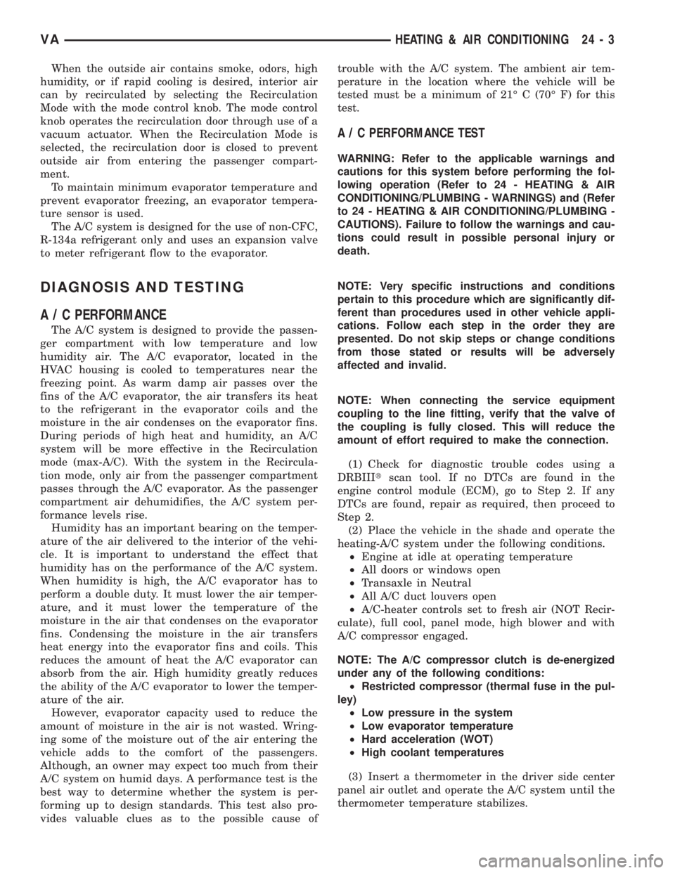
When the outside air contains smoke, odors, high
humidity, or if rapid cooling is desired, interior air
can by recirculated by selecting the Recirculation
Mode with the mode control knob. The mode control
knob operates the recirculation door through use of a
vacuum actuator. When the Recirculation Mode is
selected, the recirculation door is closed to prevent
outside air from entering the passenger compart-
ment.
To maintain minimum evaporator temperature and
prevent evaporator freezing, an evaporator tempera-
ture sensor is used.
The A/C system is designed for the use of non-CFC,
R-134a refrigerant only and uses an expansion valve
to meter refrigerant flow to the evaporator.
DIAGNOSIS AND TESTING
A / C PERFORMANCE
The A/C system is designed to provide the passen-
ger compartment with low temperature and low
humidity air. The A/C evaporator, located in the
HVAC housing is cooled to temperatures near the
freezing point. As warm damp air passes over the
fins of the A/C evaporator, the air transfers its heat
to the refrigerant in the evaporator coils and the
moisture in the air condenses on the evaporator fins.
During periods of high heat and humidity, an A/C
system will be more effective in the Recirculation
mode (max-A/C). With the system in the Recircula-
tion mode, only air from the passenger compartment
passes through the A/C evaporator. As the passenger
compartment air dehumidifies, the A/C system per-
formance levels rise.
Humidity has an important bearing on the temper-
ature of the air delivered to the interior of the vehi-
cle. It is important to understand the effect that
humidity has on the performance of the A/C system.
When humidity is high, the A/C evaporator has to
perform a double duty. It must lower the air temper-
ature, and it must lower the temperature of the
moisture in the air that condenses on the evaporator
fins. Condensing the moisture in the air transfers
heat energy into the evaporator fins and coils. This
reduces the amount of heat the A/C evaporator can
absorb from the air. High humidity greatly reduces
the ability of the A/C evaporator to lower the temper-
ature of the air.
However, evaporator capacity used to reduce the
amount of moisture in the air is not wasted. Wring-
ing some of the moisture out of the air entering the
vehicle adds to the comfort of the passengers.
Although, an owner may expect too much from their
A/C system on humid days. A performance test is the
best way to determine whether the system is per-
forming up to design standards. This test also pro-
vides valuable clues as to the possible cause oftrouble with the A/C system. The ambient air tem-
perature in the location where the vehicle will be
tested must be a minimum of 21É C (70É F) for this
test.
A / C PERFORMANCE TEST
WARNING: Refer to the applicable warnings and
cautions for this system before performing the fol-
lowing operation (Refer to 24 - HEATING & AIR
CONDITIONING/PLUMBING - WARNINGS) and (Refer
to 24 - HEATING & AIR CONDITIONING/PLUMBING -
CAUTIONS). Failure to follow the warnings and cau-
tions could result in possible personal injury or
death.
NOTE: Very specific instructions and conditions
pertain to this procedure which are significantly dif-
ferent than procedures used in other vehicle appli-
cations. Follow each step in the order they are
presented. Do not skip steps or change conditions
from those stated or results will be adversely
affected and invalid.
NOTE: When connecting the service equipment
coupling to the line fitting, verify that the valve of
the coupling is fully closed. This will reduce the
amount of effort required to make the connection.
(1) Check for diagnostic trouble codes using a
DRBIIItscan tool. If no DTCs are found in the
engine control module (ECM), go to Step 2. If any
DTCs are found, repair as required, then proceed to
Step 2.
(2) Place the vehicle in the shade and operate the
heating-A/C system under the following conditions.
²Engine at idle at operating temperature
²All doors or windows open
²Transaxle in Neutral
²All A/C duct louvers open
²A/C-heater controls set to fresh air (NOT Recir-
culate), full cool, panel mode, high blower and with
A/C compressor engaged.
NOTE: The A/C compressor clutch is de-energized
under any of the following conditions:
²Restricted compressor (thermal fuse in the pul-
ley)
²Low pressure in the system
²Low evaporator temperature
²Hard acceleration (WOT)
²High coolant temperatures
(3) Insert a thermometer in the driver side center
panel air outlet and operate the A/C system until the
thermometer temperature stabilizes.
VAHEATING & AIR CONDITIONING 24 - 3
Page 2041 of 2305
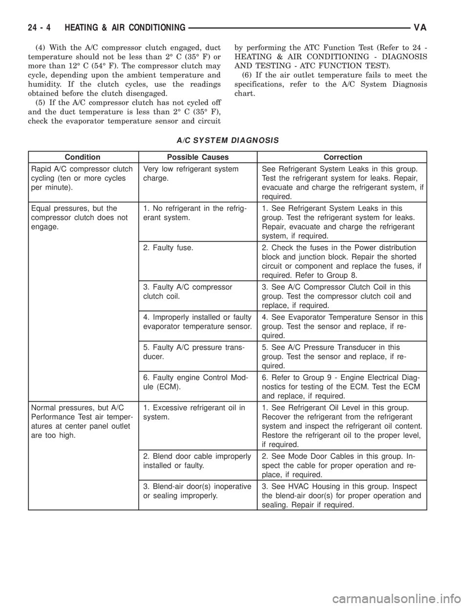
(4) With the A/C compressor clutch engaged, duct
temperature should not be less than 2É C (35É F) or
more than 12É C (54É F). The compressor clutch may
cycle, depending upon the ambient temperature and
humidity. If the clutch cycles, use the readings
obtained before the clutch disengaged.
(5) If the A/C compressor clutch has not cycled off
and the duct temperature is less than 2É C (35É F),
check the evaporator temperature sensor and circuitby performing the ATC Function Test (Refer to 24 -
HEATING & AIR CONDITIONING - DIAGNOSIS
AND TESTING - ATC FUNCTION TEST).
(6) If the air outlet temperature fails to meet the
specifications, refer to the A/C System Diagnosis
chart.
A/C SYSTEM DIAGNOSIS
Condition Possible Causes Correction
Rapid A/C compressor clutch
cycling (ten or more cycles
per minute).Very low refrigerant system
charge.See Refrigerant System Leaks in this group.
Test the refrigerant system for leaks. Repair,
evacuate and charge the refrigerant system, if
required.
Equal pressures, but the
compressor clutch does not
engage.1. No refrigerant in the refrig-
erant system.1. See Refrigerant System Leaks in this
group. Test the refrigerant system for leaks.
Repair, evacuate and charge the refrigerant
system, if required.
2. Faulty fuse. 2. Check the fuses in the Power distribution
block and junction block. Repair the shorted
circuit or component and replace the fuses, if
required. Refer to Group 8.
3. Faulty A/C compressor
clutch coil.3. See A/C Compressor Clutch Coil in this
group. Test the compressor clutch coil and
replace, if required.
4. Improperly installed or faulty
evaporator temperature sensor.4. See Evaporator Temperature Sensor in this
group. Test the sensor and replace, if re-
quired.
5. Faulty A/C pressure trans-
ducer.5. See A/C Pressure Transducer in this
group. Test the sensor and replace, if re-
quired.
6. Faulty engine Control Mod-
ule (ECM).6. Refer to Group 9 - Engine Electrical Diag-
nostics for testing of the ECM. Test the ECM
and replace, if required.
Normal pressures, but A/C
Performance Test air temper-
atures at center panel outlet
are too high.1. Excessive refrigerant oil in
system.1. See Refrigerant Oil Level in this group.
Recover the refrigerant from the refrigerant
system and inspect the refrigerant oil content.
Restore the refrigerant oil to the proper level,
if required.
2. Blend door cable improperly
installed or faulty.2. See Mode Door Cables in this group. In-
spect the cable for proper operation and re-
place, if required.
3. Blend-air door(s) inoperative
or sealing improperly.3. See HVAC Housing in this group. Inspect
the blend-air door(s) for proper operation and
sealing. Repair if required.
24 - 4 HEATING & AIR CONDITIONINGVA
Page 2043 of 2305
²Mode control in the floor heat position
²Blower motor control in the highest speed posi-
tion
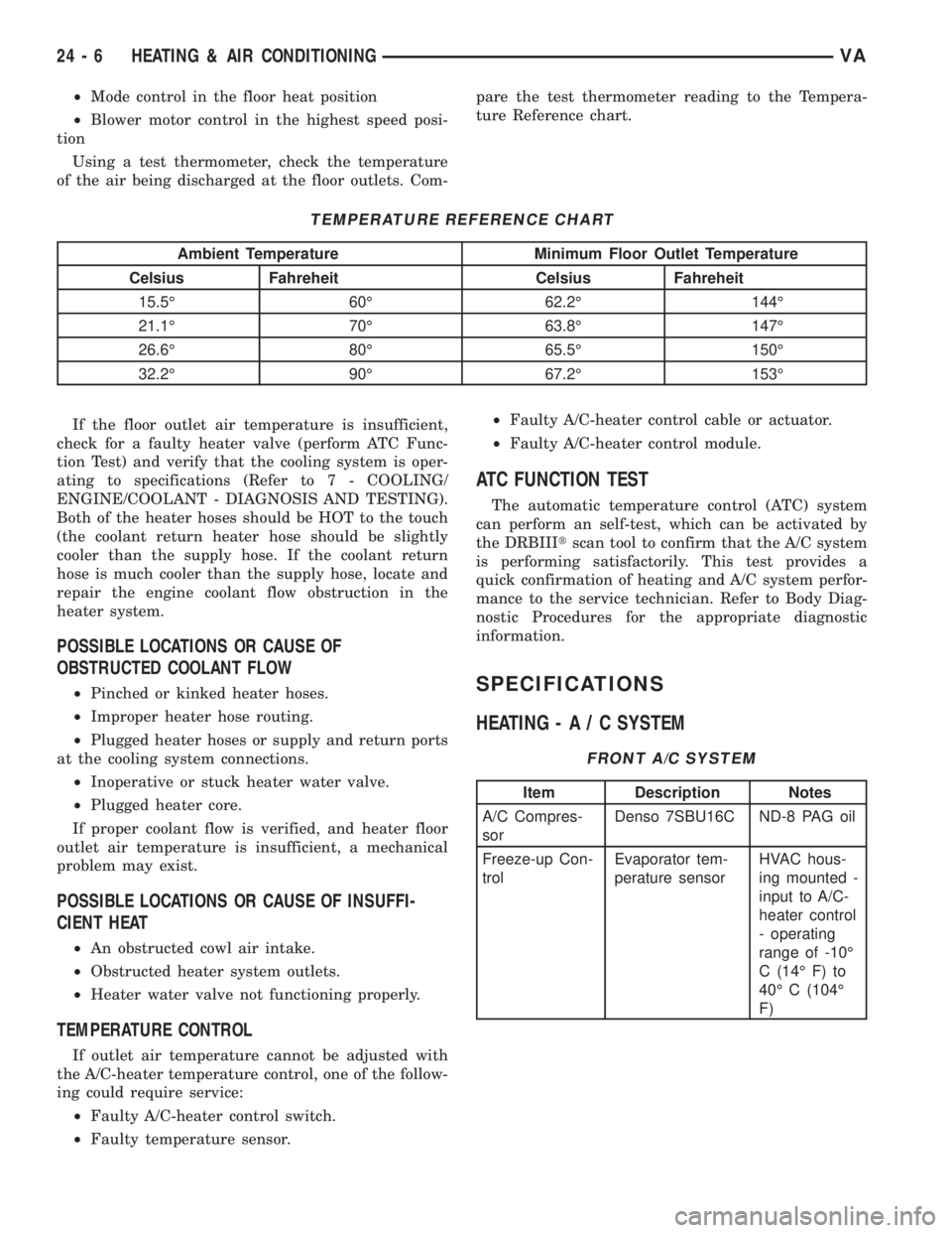
Using a test thermometer, check the temperature
of the air being discharged at the floor outlets. Com-pare the test thermometer reading to the Tempera-
ture Reference chart.
TEMPERATURE REFERENCE CHART
Ambient Temperature Minimum Floor Outlet Temperature
Celsius Fahreheit Celsius Fahreheit
15.5É 60É 62.2É 144É
21.1É 70É 63.8É 147É
26.6É 80É 65.5É 150É
32.2É 90É 67.2É 153É
If the floor outlet air temperature is insufficient,
check for a faulty heater valve (perform ATC Func-
tion Test) and verify that the cooling system is oper-
ating to specifications (Refer to 7 - COOLING/
ENGINE/COOLANT - DIAGNOSIS AND TESTING).
Both of the heater hoses should be HOT to the touch
(the coolant return heater hose should be slightly
cooler than the supply hose. If the coolant return
hose is much cooler than the supply hose, locate and
repair the engine coolant flow obstruction in the
heater system.
POSSIBLE LOCATIONS OR CAUSE OF
OBSTRUCTED COOLANT FLOW
²Pinched or kinked heater hoses.
²Improper heater hose routing.
²Plugged heater hoses or supply and return ports
at the cooling system connections.
²Inoperative or stuck heater water valve.
²Plugged heater core.
If proper coolant flow is verified, and heater floor
outlet air temperature is insufficient, a mechanical
problem may exist.
POSSIBLE LOCATIONS OR CAUSE OF INSUFFI-
CIENT HEAT
²An obstructed cowl air intake.
²Obstructed heater system outlets.
²Heater water valve not functioning properly.
TEMPERATURE CONTROL
If outlet air temperature cannot be adjusted with
the A/C-heater temperature control, one of the follow-
ing could require service:
²Faulty A/C-heater control switch.
²Faulty temperature sensor.²Faulty A/C-heater control cable or actuator.
²Faulty A/C-heater control module.
ATC FUNCTION TEST
The automatic temperature control (ATC) system
can perform an self-test, which can be activated by
the DRBIIItscan tool to confirm that the A/C system
is performing satisfactorily. This test provides a
quick confirmation of heating and A/C system perfor-
mance to the service technician. Refer to Body Diag-
nostic Procedures for the appropriate diagnostic
information.
SPECIFICATIONS
HEATING-A/CSYSTEM
FRONT A/C SYSTEM
Item Description Notes
A/C Compres-
sorDenso 7SBU16C ND-8 PAG oil
Freeze-up Con-
trolEvaporator tem-
perature sensorHVAC hous-
ing mounted -
input to A/C-
heater control
- operating
range of -10É
C (14É F) to
40É C (104É
F)
24 - 6 HEATING & AIR CONDITIONINGVA