2006 MERCEDES-BENZ SPRINTER check oil
[x] Cancel search: check oilPage 2046 of 2305
OPERATION
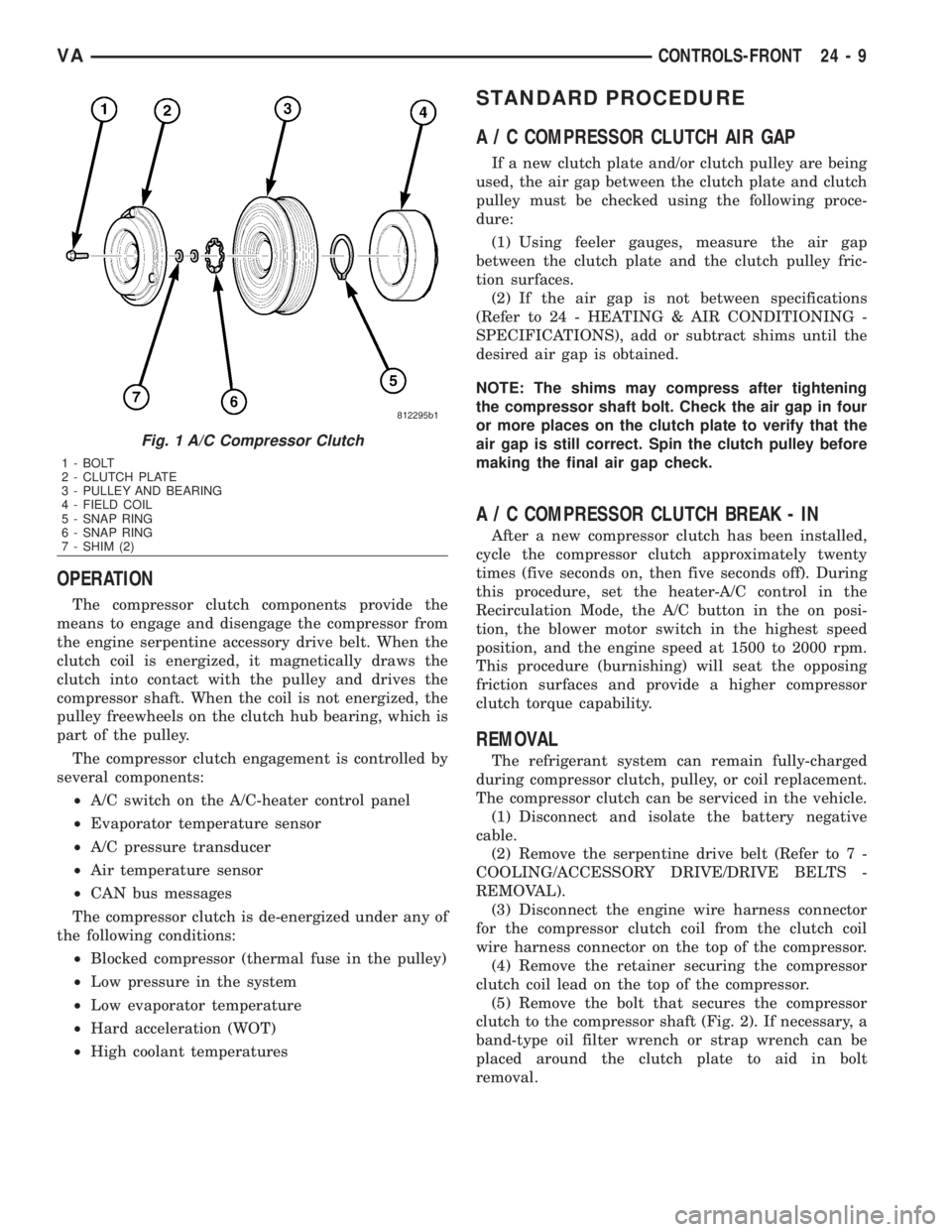
The compressor clutch components provide the
means to engage and disengage the compressor from
the engine serpentine accessory drive belt. When the
clutch coil is energized, it magnetically draws the
clutch into contact with the pulley and drives the
compressor shaft. When the coil is not energized, the
pulley freewheels on the clutch hub bearing, which is
part of the pulley.
The compressor clutch engagement is controlled by
several components:
²A/C switch on the A/C-heater control panel
²Evaporator temperature sensor
²A/C pressure transducer
²Air temperature sensor
²CAN bus messages
The compressor clutch is de-energized under any of
the following conditions:
²Blocked compressor (thermal fuse in the pulley)
²Low pressure in the system
²Low evaporator temperature
²Hard acceleration (WOT)
²High coolant temperatures
STANDARD PROCEDURE
A / C COMPRESSOR CLUTCH AIR GAP
If a new clutch plate and/or clutch pulley are being
used, the air gap between the clutch plate and clutch
pulley must be checked using the following proce-
dure:
(1) Using feeler gauges, measure the air gap
between the clutch plate and the clutch pulley fric-
tion surfaces.
(2) If the air gap is not between specifications
(Refer to 24 - HEATING & AIR CONDITIONING -
SPECIFICATIONS), add or subtract shims until the
desired air gap is obtained.
NOTE: The shims may compress after tightening
the compressor shaft bolt. Check the air gap in four
or more places on the clutch plate to verify that the
air gap is still correct. Spin the clutch pulley before
making the final air gap check.
A / C COMPRESSOR CLUTCH BREAK - IN
After a new compressor clutch has been installed,
cycle the compressor clutch approximately twenty
times (five seconds on, then five seconds off). During
this procedure, set the heater-A/C control in the
Recirculation Mode, the A/C button in the on posi-
tion, the blower motor switch in the highest speed
position, and the engine speed at 1500 to 2000 rpm.
This procedure (burnishing) will seat the opposing
friction surfaces and provide a higher compressor
clutch torque capability.
REMOVAL
The refrigerant system can remain fully-charged
during compressor clutch, pulley, or coil replacement.
The compressor clutch can be serviced in the vehicle.
(1) Disconnect and isolate the battery negative
cable.
(2) Remove the serpentine drive belt (Refer to 7 -
COOLING/ACCESSORY DRIVE/DRIVE BELTS -
REMOVAL).
(3) Disconnect the engine wire harness connector
for the compressor clutch coil from the clutch coil
wire harness connector on the top of the compressor.
(4) Remove the retainer securing the compressor
clutch coil lead on the top of the compressor.
(5) Remove the bolt that secures the compressor
clutch to the compressor shaft (Fig. 2). If necessary, a
band-type oil filter wrench or strap wrench can be
placed around the clutch plate to aid in bolt
removal.
Fig. 1 A/C Compressor Clutch
1 - BOLT
2 - CLUTCH PLATE
3 - PULLEY AND BEARING
4 - FIELD COIL
5 - SNAP RING
6 - SNAP RING
7 - SHIM (2)
VACONTROLS-FRONT 24 - 9
Page 2048 of 2305
INSPECTION
Compressor clutch components should always be
inspected closely before they are reinstalled. The
clutch plate and clutch pulley are mated at the fac-
tory using a burnishing operation. No attempt should
be made to separately replace the compressor clutch
pulley or clutch plate. The clutch coil may be serviced
separately.
(1) Examine the friction surfaces of the clutch pul-
ley and the clutch plate for wear. The clutch pulley
and clutch plate should be replaced if there is exces-
sive wear or scoring.
(2) Examine the friction surfaces of the clutch pul-
ley and the clutch plate for oil contamination. If the
friction surfaces are oily, the clutch pulley and clutch
plate should be replaced. Also inspect the shaft and
nose area of the compressor for oil. Remove the felt
packing from around the compressor shaft in the
compressor front cover. If the felt is saturated with
oil, the compressor front shaft seal is leaking and the
compressor will also have to be replaced.
(3) Check the clutch pulley bearing for roughness
or excessive leakage of grease. Replace the clutch
pulley and clutch plate if the bearing is faulty.
INSTALLATION
(1) Align the dowel pin on the back of the clutch
field coil with the hole in the compressor front cover,
and position the clutch coil onto the compressor. Be
certain that the cluch coil wire harness leads are
properly oriented and routed so that they are notpinched between the compressor front cover and the
clutch coil.
NOTE: A new snap ring must be used to secure the
clutch coil to the compressor. The bevel side of the
snap ring must face outward.
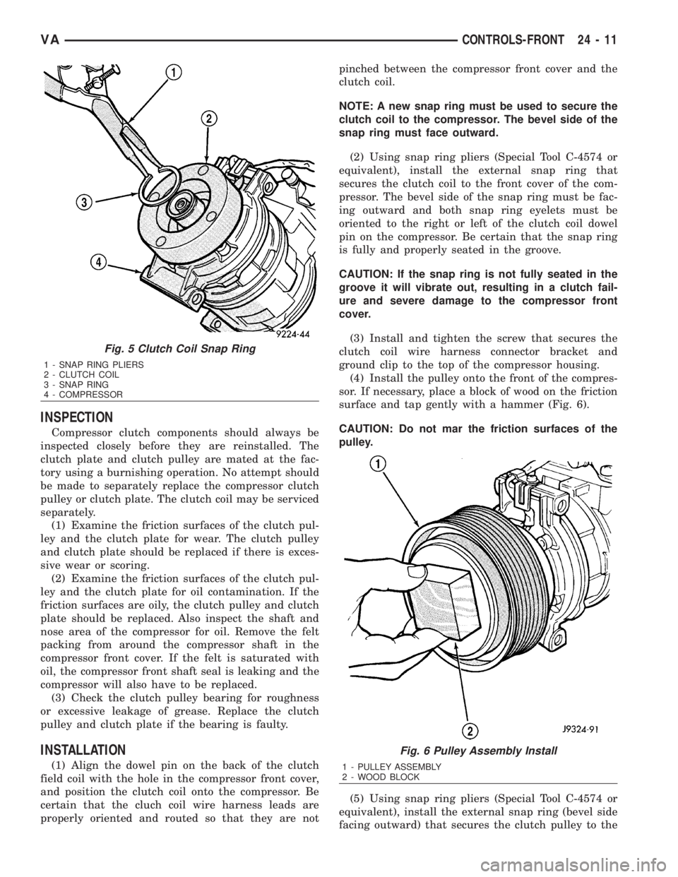
(2) Using snap ring pliers (Special Tool C-4574 or
equivalent), install the external snap ring that
secures the clutch coil to the front cover of the com-
pressor. The bevel side of the snap ring must be fac-
ing outward and both snap ring eyelets must be
oriented to the right or left of the clutch coil dowel
pin on the compressor. Be certain that the snap ring
is fully and properly seated in the groove.
CAUTION: If the snap ring is not fully seated in the
groove it will vibrate out, resulting in a clutch fail-
ure and severe damage to the compressor front
cover.
(3) Install and tighten the screw that secures the
clutch coil wire harness connector bracket and
ground clip to the top of the compressor housing.
(4) Install the pulley onto the front of the compres-
sor. If necessary, place a block of wood on the friction
surface and tap gently with a hammer (Fig. 6).
CAUTION: Do not mar the friction surfaces of the
pulley.
(5) Using snap ring pliers (Special Tool C-4574 or
equivalent), install the external snap ring (bevel side
facing outward) that secures the clutch pulley to the
Fig. 5 Clutch Coil Snap Ring
1 - SNAP RING PLIERS
2 - CLUTCH COIL
3 - SNAP RING
4 - COMPRESSOR
Fig. 6 Pulley Assembly Install
1 - PULLEY ASSEMBLY
2 - WOOD BLOCK
VACONTROLS-FRONT 24 - 11
Page 2049 of 2305
front cover of the compressor. Be certain that the
snap ring is properly fully and properly seated in the
groove.
(6) If the original clutch plate and clutch pulley
are to be reused, reinstall the original shim(s) on the
compressor shaft against the shoulder. If a new
clutch plate and/or clutch pulley are being used,
install a trial stack of shims 1.0 mm (0.040 in.) thick
on the compressor shaft against the shoulder.
(7) Install the clutch plate onto the compressor
shaft.
(8) Install and tighten the compressor shaft bolt. If
necessary, a band-type oil filter wrench or a strap
wrench can be placed around the clutch plate to aid
in bolt tightening. Tighten the bolt to 17.5 N´m (155
in. lbs.).
NOTE: The shims may compress after tightening
the shaft bolt. Check the air gap in four or more
places to verify the air gap is still correct. Spin the
pulley before performing a final check of the air
gap.
(9) If a new clutch plate and/or clutch pulley are
being installed, the air gap between the clutch plate
and clutch pulley must be checked (Refer to 24 -
HEATING & AIR CONDITIONING/CONTROLS/A/C
COMPRESSOR CLUTCH - STANDARD PROCE-
DURE).
(10) Install the retainer that secures the compres-
sor clutch coil lead to the top of the compressor.
(11) Reconnect the engine wire harness connector
to the clutch coil lead on the top of the compressor.
(12) Reinstall the serpentine accessory drive belt
(Refer to 7 - COOLING/ACCESSORY DRIVE/DRIVE
BELTS - INSTALLATION).
(13) Reconnect the battery negative cable.
(14) If a new clutch plate and/or clutch pulley are
being installed, the new clutch components must be
burnished (Refer to 24 - HEATING & AIR CONDI-
TIONING/CONTROLS/A/C COMPRESSOR CLUTCH
- STANDARD PROCEDURE).
A / C COMPRESSOR CLUTCH
COIL
DIAGNOSIS AND TESTING
A / C COMPRESSOR CLUTCH COIL
The air conditioning compressor clutch coil electri-
cal circuit is controlled by the ATC control module
which is integral to the heater-A/C control. Begin
testing of a suspected compressor clutch coil problem
by performing the ATC Function Test using the
DRBIIItscan tool.PRELIMINARY CHECKS
(1) If no diagnostic trouble codes (DTCs) are found
in the A/C-heater control or the powertrain control
module (PCM), go to Step 2. If any DTCs are found,
repair as required.
(2) If the A/C compressor clutch still will not
engage, verify the refrigerant charge level (Refer to
24 - HEATING & AIR CONDITIONING/PLUMBING
- DIAGNOSIS AND TESTING - REFRIGERANT
SYSTEM LEAKS). If the refrigerant charge level is
OK, go to TESTS. If the refrigerant charge level is
not OK, adjust the refrigerant charge as required.
TESTS
(1) Verify the battery state of charge (Refer to 8 -
ELECTRICAL/BATTERY SYSTEM/BATTERY -
DIAGNOSIS AND TESTING).
(2) Connect an ammeter (0 to 10 ampere scale
selected) in series with the clutch coil feed terminal.
Connect a voltmeter (0 to 20 volt scale selected) to
measure voltage across the battery and the clutch
coil.
(3) With the A/C-heater control in the A/C mode
and the blower motor at low speed, start the engine
and allow it to run at a normal idle speed.
(4) The A/C compressor clutch should engage
immediately, and the clutch coil supply voltage
should be within two volts of the battery voltage. If
the coil supply voltage is OK, go to Step 5. If the coil
supply voltage is not within two volts of battery volt-
age, test the clutch coil feed circuit for excessive volt-
age drop and repair as necessary.
(5) For the acceptable A/C clutch coil current draw
specifications refer to 24 - HEATING & AIR CONDI-
TIONING - SPECIFICATIONS. Specifications apply
for a work area temperature of 21É C (70É F). If volt-
age is more than 12.5 volts, add electrical loads by
turning on electrical accessories until voltage reads
below 12.5 volts.
(a) If the A/C clutch coil current reading is zero,
the coil is open and must be replaced.
(b) If the A/C clutch coil current reading is above
specifications, the coil is shorted and must be
replaced.
A / C HEATER CONTROL
DESCRIPTION
This ATC system uses a combination of electrical
and mechanical controls. These controls provide the
vehicle operator with a number of setting options to
help control the climate and comfort within the vehi-
cle.
The A/C-heater control is located on the instrument
panel inboard of the steering column and below the
24 - 12 CONTROLS-FRONTVA
Page 2102 of 2305
CAUTION: A small amount of refrigerant oil is
removed from the A/C system each time the refrig-
erant system is recovered and evacuated. Before
charging the A/C system, you MUST replenish any
oil lost during the recovery process. Refer the
equipment manufacturer instructions for more infor-
mation.
After the refrigerant system has been tested for
leaks and evacuated, a refrigerant charge can be
injected into the system. (Refer to 24 - HEATING &
AIR CONDITIONING/PLUMBING - SPECIFICA-
TIONS - CHARGE CAPACITY)
A R-134a refrigerant recovery/recycling/charging
station that meets SAE Standard J2210 must be
used to charge the refrigerant system with R-134a
refrigerant. Refer to the operating instructions sup-
plied by the equipment manufacturer for proper care
and use of this equipment.
PARTIAL CHARGE METHOD
The partial charge method is used to add a partial
charge to a refrigerant system that is low on refrig-
erant. To perform this procedure the evaporator inlet
and outlet tube temperatures are measured. The
temperature difference is measured with a tempera-
ture meter with one or two clamp-on thermocouple
probes. The difference between the evaporator inlet
and outlet tube temperatures will determine the
amount of refrigerant needed.
Before adding a partial refrigerant charge, check
for refrigerant system leaks. (Refer to 24 - HEATING
& AIR CONDITIONING/PLUMBING - DIAGNOSIS
AND TESTING - REFRIGERANT SYSTEM LEAKS)
If a leak is found, make the necessary repairs before
attempting a full or partial refrigerant charge.
(1) Attach a manifold gauge set to the refrigerant
system service ports.
(2) Attach the two clamp-on thermocouple probes
to the inlet and outlet tubes of the evaporator coil.
²If a single thermocouple probe is used, attach
the probe to the evaporator inlet tube just before the
collar of the refrigerant line connector fitting. The
probe must make contact with the bottom surface of
the evaporator inlet tube.
²If dual thermocouple probes are used, attach
probe 1 to the evaporator inlet tube, and probe 2 to
the evaporator outlet tube. Attach both probes to the
evaporator tubes just before the collar of the refrig-erant line connector fittings. The probes must make
contact with the bottom surfaces of the evaporator
inlet and outlet tubes.
(3) Open all of the windows or doors of the passen-
ger compartment.
(4) Set the A/C button on the A/C Heater controls
to the on position, the temperature control knob in
the full cool position, select Recirculation Mode, and
place the blower motor switch in the highest speed
position.
(5) Start the engine and hold the engine idle speed
at 1,000 rpm. Allow the engine to warm up to normal
operating temperature.
(6) The compressor clutch may cycle, depending
upon ambient temperature, humidity, and the refrig-
erant system charge level.
(7) Hold the engine idle speed at 1,000 rpm.
(8) Allow three to five minutes for the refrigerant
system to stabilize, then record the temperatures of
the evaporator inlet and outlet tubes.
²If a single probe is used, record the temperature
of the evaporator inlet tube. Then remove the probe
from the inlet tube and attach it to the evaporator
outlet tube just before the collar of the refrigerant
line connector fitting. The probe must make contact
with the bottom surface of the evaporator outlet tube.
Allow the thermocouple and meter time to stabilize,
then record the temperature of the evaporator outlet
tube. Subtract the inlet tube temperature reading
from the outlet tube temperature reading.
²If dual probes are used, record the temperatures
of both the evaporator inlet and outlet tubes. Then
subtract the inlet tube temperature reading from the
outlet tube temperature reading.
(9) If the measured temperature differential is
higher than 22É C to 26É C (40É F to 47É F), add 0.4
kilograms (14 ounces) of refrigerant.
(10) Allow three to five minutes for the refrigerant
system to stabilize, then take a second set of thermo-
couple measurements. Record the temperature differ-
ence to determine if an additional charge is required.
(11) Record the compressor discharge pressure. If
the reading is higher than the pressure shown in the
Compressor Discharge Pressure Chart, the system
could be overcharged. If the reading is equal to, or
lower, than the pressure shown in the chart, continue
with this procedure.
Compressor Discharge Pressure Chart
Ambient Tempera-
ture16ÉC
(60ÉF)21ÉC
(70ÉF)27ÉC
(80ÉF)32ÉC
(90ÉF)38ÉC
(100ÉF)43ÉC
(110ÉF)
Compressor Dis-
charge Pressure1378 kPa
(200 psi)1516 kPa
(220 psi)1723 kPa
(250psi)1930 kPa
(280 psi)2206 kPa
(320 psi)2413 kPa
(350 psi)
VAPLUMBING 24 - 65
Page 2104 of 2305
mounting brackets, or a loose compressor clutch
assembly.
Drive belts are speed sensitive. At different engine
speeds and depending upon belt tension, belts can
develop noises that are mistaken for a compressor
noise. Improper belt tension can cause a misleading
noise when the compressor clutch is engaged, which
may not occur when the compressor clutch is disen-
gaged. Check the serpentine drive belt condition and
tension as described in Cooling before beginning this
procedure.
(1) Select a quiet area for testing. Duplicate the
complaint conditions as much as possible. Switch the
compressor on and off several times to clearly iden-
tify the compressor noise. Listen to the compressor
while the clutch is engaged and disengaged. Probe
the compressor with an engine stethoscope or a long
screwdriver with the handle held to your ear to bet-
ter localize the source of the noise.
(2) Loosen all of the compressor mounting hard-
ware and retighten. Tighten the compressor clutch
mounting nut. Be certain that the clutch coil is
mounted securely to the compressor, and that the
clutch plate and pulley are properly aligned and have
the correct air gap. (Refer to 24 - HEATING & AIR
CONDITIONING/CONTROLS/A/C COMPRESSOR
CLUTCH - INSTALLATION)
(3) To duplicate a high-ambient temperature condi-
tion (high head pressure), restrict the air flow
through the condenser. Install a manifold gauge set
to be certain that the discharge pressure does not
exceed 2760 kPa (400 psi).
(4) Check the refrigerant system plumbing for
incorrect routing, rubbing or interference, which can
cause unusual noises. Also check the refrigerant lines
for kinks or sharp bends that will restrict refrigerant
flow, which can cause noises. (Refer to 24 - HEAT-
ING & AIR CONDITIONING/PLUMBING - CAU-
TION - REFRIGERANT HOSES/LINES/TUBES
PRECAUTIONS)
(5) If the noise is from opening and closing of the
high pressure relief valve, reclaim, evacuate, and
recharge the refrigerant system. (Refer to 24 - HEAT-
ING & AIR CONDITIONING/PLUMBING - STAN-
DARD PROCEDURE - REFRIGERANT RECOVERY)
(Refer to 24 - HEATING & AIR CONDITIONING/
PLUMBING - STANDARD PROCEDURE - REFRIG-
ERANT SYSTEM EVACUATE) (Refer to 24 -
HEATING & AIR CONDITIONING/PLUMBING -
STANDARD PROCEDURE - REFRIGERANT SYS-
TEM CHARGE) If the high pressure relief valve still
does not seat properly, replace the a/c compressor.
(Refer to 24 - HEATING & AIR CONDITIONING/
PLUMBING/A/C COMPRESSOR - REMOVAL)
(6) If the noise is from liquid slugging on the suc-
tion line, check the refrigerant oil level and the
refrigerant system charge. (Refer to 24 - HEATING
& AIR CONDITIONING/PLUMBING/REFRIGER-ANT OIL - STANDARD PROCEDURE) (Refer to 24 -
HEATING & AIR CONDITIONING/PLUMBING -
SPECIFICATIONS - CHARGE CAPACITY).
(7) If the noise continues, replace the compressor
and repeat Step 1.
REMOVAL
DENSO 7SBU16CA/CCOMPRESSOR
WARNING: Refer to the applicable warnings and
cautions for this system before performing the fol-
lowing operation (Refer to 24 - HEATING & AIR
CONDITIONING/PLUMBING - WARNINGS) and (Refer
to 24 - HEATING & AIR CONDITIONING/PLUMBING -
CAUTIONS). Failure to follow the warnings and cau-
tions could result in possible personal injury or
death.
NOTE: The A/C compressor may be removed and
repositioned without disconnecting the refrigerant
lines or discharging the refrigerant system. Dis-
charging is not necessary if servicing the compres-
sor clutch, clutch coil or the engine.
NOTE: If an internal failure of the A/C compressor
has occurred, the receiver/drier must be replaced.
(1) Disconnect and isolate the negative battery
cable.
(2) Recover the refrigerant from the refrigerant
system (Refer to 24 - HEATING & AIR CONDITION-
ING/PLUMBING - STANDARD PROCEDURE -
REFRIGERANT SYSTEM RECOVERY).
(3) Remove the serpentine drive belt (Refer to 7 -
COOLING/ACCESSORY DRIVE/BELTS-DRIVE -
REMOVAL).
(4) Disconnect the wire harness connector from the
A/C compressor clutch coil.
(5) Remove the bolts that secure the A/C suction
and discharge lines to the A/C compressor.
(6) Disconnect the A/C suction and discharge lines
from the A/C compressor and remove and discard the
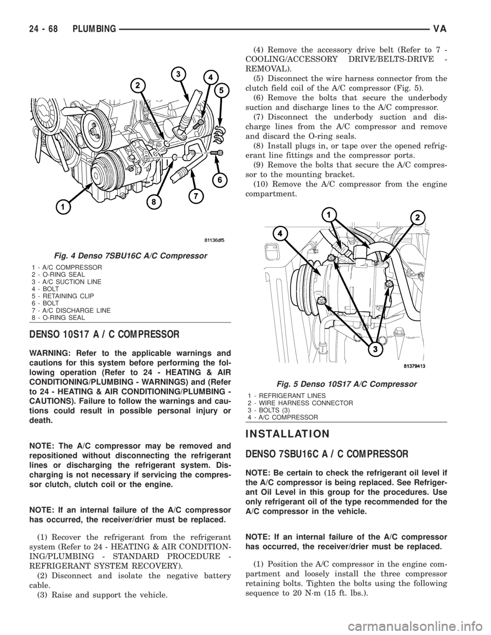
O-ring seals (Fig. 4).
(7) Install plugs in, or tape over the opened refrig-
erant line fittings and the compressor ports.
(8) Raise the vehicle on a hoist.
(9) If equipped with an add-on rear A/C system,
remove the lower A/C compressor and position it out
of the way (Refer to 24 - HEATING & AIR CONDI-
TIONING/PLUMBING/A/C COMPRESSOR -
REMOVAL - DENSO 10S17).
(10) Support the A/C compressor and remove the
compressor mounting bolts.
(11) Remove the A/C compressor from the engine
compartment.
VAPLUMBING 24 - 67
Page 2105 of 2305
DENSO 10S17A/CCOMPRESSOR
WARNING: Refer to the applicable warnings and
cautions for this system before performing the fol-
lowing operation (Refer to 24 - HEATING & AIR
CONDITIONING/PLUMBING - WARNINGS) and (Refer
to 24 - HEATING & AIR CONDITIONING/PLUMBING -
CAUTIONS). Failure to follow the warnings and cau-
tions could result in possible personal injury or
death.
NOTE: The A/C compressor may be removed and
repositioned without disconnecting the refrigerant
lines or discharging the refrigerant system. Dis-
charging is not necessary if servicing the compres-
sor clutch, clutch coil or the engine.
NOTE: If an internal failure of the A/C compressor
has occurred, the receiver/drier must be replaced.
(1) Recover the refrigerant from the refrigerant
system (Refer to 24 - HEATING & AIR CONDITION-
ING/PLUMBING - STANDARD PROCEDURE -
REFRIGERANT SYSTEM RECOVERY).
(2) Disconnect and isolate the negative battery
cable.
(3) Raise and support the vehicle.(4) Remove the accessory drive belt (Refer to 7 -
COOLING/ACCESSORY DRIVE/BELTS-DRIVE -
REMOVAL).
(5) Disconnect the wire harness connector from the
clutch field coil of the A/C compressor (Fig. 5).
(6) Remove the bolts that secure the underbody
suction and discharge lines to the A/C compressor.
(7) Disconnect the underbody suction and dis-
charge lines from the A/C compressor and remove
and discard the O-ring seals.
(8) Install plugs in, or tape over the opened refrig-
erant line fittings and the compressor ports.
(9) Remove the bolts that secure the A/C compres-
sor to the mounting bracket.
(10) Remove the A/C compressor from the engine
compartment.
INSTALLATION
DENSO 7SBU16CA/CCOMPRESSOR
NOTE: Be certain to check the refrigerant oil level if
the A/C compressor is being replaced. See Refriger-
ant Oil Level in this group for the procedures. Use
only refrigerant oil of the type recommended for the
A/C compressor in the vehicle.
NOTE: If an internal failure of the A/C compressor
has occurred, the receiver/drier must be replaced.
(1) Position the A/C compressor in the engine com-
partment and loosely install the three compressor
retaining bolts. Tighten the bolts using the following
sequence to 20 N´m (15 ft. lbs.).
Fig. 4 Denso 7SBU16C A/C Compressor
1 - A/C COMPRESSOR
2 - O-RING SEAL
3 - A/C SUCTION LINE
4 - BOLT
5 - RETAINING CLIP
6 - BOLT
7 - A/C DISCHARGE LINE
8 - O-RING SEAL
Fig. 5 Denso 10S17 A/C Compressor
1 - REFRIGERANT LINES
2 - WIRE HARNESS CONNECTOR
3 - BOLTS (3)
4 - A/C COMPRESSOR
24 - 68 PLUMBINGVA
Page 2106 of 2305
²The upper bolt at the front of the compressor.
²The lower bolt at the front of the compressor.
²The bolt at the rear of the compressor.
(2) If equipped with an add-on rear A/C system,
install the lower A/C compressor (Refer to 24 - HEAT-
ING & AIR CONDITIONING/PLUMBING/A/C COM-
PRESSOR - INSTALLATION - DENSO 10S17).
(3) Lower the vehicle.
(4) Remove the tape or plugs from the opened suc-
tion line fitting and the discharge line fitting and the
compressor ports.
(5) Lubricate new rubber O-ring seals with clean
refrigerant oil and install them onto the suction and
the discharge line fittings. Use only the specified
O-rings as they are made of a special material for the
R-134a system. Use only refrigerant oil of the type
recommended for the A/C compressor in the vehicle.
(6) Connect the A/C suction and discharge lines to
the A/C compressor.
(7) Install the bolts that secure the A/C suction
and discharge lines to the A/C compressor. Tighten
the bolts to 23 N´m (17 ft. lbs.).
(8) Connect the wire harness connector to the A/C
compressor clutch coil.
(9) Install the accessory drive belt (Refer to 7 -
COOLING/ACCESSORY DRIVE/DRIVE BELTS -
INSTALLATION).
(10) Replace the receiver/drier if the A/C compres-
sor is being replaced due to an internal failure (Refer
to 24 - HEATING & AIR CONDITIONING/PLUMB-
ING/RECEIVER/DRIER - REMOVAL) and (Refer to
24 - HEATING & AIR CONDITIONING/PLUMBING/
RECEIVER/DRIER - INSTALLATION).
(11) Reconnect the negative battery cable.
(12) Evacuate the refrigerant system (Refer to 24 -
HEATING & AIR CONDITIONING/PLUMBING -
STANDARD PROCEDURE - REFRIGERANT SYS-
TEM EVACUATE).
(13) Charge the refrigerant system (Refer to 24 -
HEATING & AIR CONDITIONING/PLUMBING -
STANDARD PROCEDURE - REFRIGERANT SYS-
TEM CHARGE).
DENSO 10S17A/CCOMPRESSOR
NOTE: Be certain to check the refrigerant oil level if
the A/C compressor is being replaced. See Refriger-
ant Oil Level in this group for the procedures. Use
only refrigerant oil of the type recommended for the
A/C compressor in the vehicle.
NOTE: If an internal failure of the A/C compressor
has occurred, the receiver/drier must be replaced.
(1) Position the A/C compressor in the engine com-
partment and loosely install the three compressorretaining bolts. Tighten the bolts using the following
sequence to 20 N´m (14 ft. lbs.).
²The upper bolt at the front of the compressor.
²The lower bolt at the front of the compressor.
²The bolt at the rear of the compressor.
(2) Remove the tape or plugs from the opened
underbody suction and discharge line fittings and
compressor ports.
(3) Lubricate new rubber O-ring seals with clean
refrigerant oil and install them onto the suction and
the discharge line fittings. Use only the specified
O-rings as they are made of a special material for the
R-134a system. Use only refrigerant oil of the type
recommended for the A/C compressor in the vehicle.
(4) Connect the underbody suction and discharge
lines to the A/C compressor.
(5) Install the bolts that secure the underbody suc-
tion and discharge lines to the A/C compressor.
Tighten the bolts to 21 N´m (15 ft. lbs.).
(6) Connect the wire harness connector to the A/C
compressor clutch coil.
(7) Install the accessory drive belt (Refer to 7 -
COOLING/ACCESSORY DRIVE/BELTS-DRIVE -
INSTALLATION).
(8) Lower the vehicle.
(9) Replace the receiver/drier if the A/C compressor
is being replaced due to an internal failure (Refer to
24 - HEATING & AIR CONDITIONING/PLUMBING/
RECEIVER/DRIER - REMOVAL) and (Refer to 24 -
HEATING & AIR CONDITIONING/PLUMBING/RE-
CEIVER/DRIER - INSTALLATION).
(10) Reconnect the negative battery cable.
(11) Evacuate the refrigerant system (Refer to 24 -
HEATING & AIR CONDITIONING/PLUMBING -
STANDARD PROCEDURE - REFRIGERANT SYS-
TEM EVACUATE).
(12) Charge the refrigerant system (Refer to 24 -
HEATING & AIR CONDITIONING/PLUMBING -
STANDARD PROCEDURE - REFRIGERANT SYS-
TEM CHARGE).
A / C CONDENSER
DESCRIPTION
The condenser is located in the air flow in front of
the engine cooling radiator. The condenser is a heat
exchanger that allows the high-pressure refrigerant
gas being discharged by the compressor to give up its
heat to the air passing over the condenser fins.
OPERATION
When the refrigerant gas gives up its heat, it con-
denses. When the refrigerant leaves the condenser, it
has become a high-pressure liquid refrigerant. The
volume of air flowing over the condenser fins is crit-
ical to the proper cooling performance of the air con-
ditioning system. Therefore, it is important that
VAPLUMBING 24 - 69
Page 2118 of 2305
all been designed with unique fittings to ensure that
an R-134a system is not accidentally contaminated
with the wrong refrigerant (R-12). There are also
labels posted in the engine compartment of the vehi-
cle and on the compressor identifying to service tech-
nicians that the air conditioning system is equipped
with R-134a.
REFRIGERANT OIL
DESCRIPTION
The refrigerant oil used in R-134a refrigerant sys-
tems is a synthetic-based, PolyAlkylene Glycol (PAG),
wax-free lubricant. Mineral-based R-12 refrigerant
oils are not compatible with PAG oils, and should
never be introduced to an R-134a refrigerant system.
There are different PAG oils available, and each
contains a different additive package. The A/C com-
pressors for this vehicle are designed to use an ND-8
PAG refrigerant oil. Use only the refrigerant oil of
this type to service the refrigerant system.
OPERATION
After performing any refrigerant recovery or recy-
cling operation, always replenish the refrigerant sys-
tem with the same amount of the recommended
refrigerant oil as was removed. Too little refrigerant
oil can cause compressor damage, and too much can
reduce air conditioning system performance.
PAG refrigerant oil is much more hygroscopic than
mineral oil, and will absorb any moisture it comes
into contact with, even moisture in the air. The PAG
oil container should always be kept tightly capped
until it is ready to be used. After use, recap the oil
container immediately to prevent moisture contami-
nation.
STANDARD PROCEDURE
REFRIGERANT OIL LEVEL
When an A/C system is assembled at the factory,
all components except the compressor are refrigerant
oil free. After the refrigerant system has been
charged and operated, the refrigerant oil in the com-
pressor is dispersed throughout the refrigerant sys-
tem. The receiver-drier, evaporator, condenser, and
compressor will each retain a significant amount of
the needed refrigerant oil.
It is important to have the correct amount of oil in
the refrigerant system. This ensures proper lubrica-
tion of the A/C compressor. Too little oil will result in
damage to the A/C compressor. Too much oil will
reduce the cooling capacity of the A/C system.
It will not be necessary to check the oil level in the
A/C compressor or to add oil, unless there has been
an oil loss. An oil loss may occur due to a rupture orleak from a refrigerant line, a connector fitting, a
component, or a component seal. If a leak occurs, add
30 milliliters (1 fluid ounce) of refrigerant oil to the
refrigerant system after the repair has been made.
Refrigerant oil loss will be evident at the leak point
by the presence of a wet, shiny surface around the
leak.
Refrigerant oil must be added when a receiver/
drier, A/C evaporator, or A/C condenser are replaced.
See the Refrigerant Oil Capacities chart. When an
A/C compressor is replaced, the refrigerant oil must
be drained from the old compressor and measured.
Drain all of the refrigerant oil from the new compres-
sor, then fill the new compressor with the same
amount of refrigerant oil that was drained out of the
old compressor.
REFRIGERANT OIL CAPACITIES
Component ml fl oz
Total A/C System Fill 410 13.9
Receiver/Drier 30 1.0
A/C Condenser 30 1.0
A/C Evaporator 60 2.0
A/C CompressorDrain and measure the oil
from the old compressor -
see text.
SUCTION LINE
REMOVAL
WARNING: Refer to the applicable warnings and
cautions for this system before performing the fol-
lowing operation (Refer to 24 - HEATING & AIR
CONDITIONING/PLUMBING - WARNINGS) and (Refer
to 24 - HEATING & AIR CONDITIONING/PLUMBING -
CAUTIONS). Failure to follow the warnings and cau-
tions could result in possible personal injury or
death.
(1) Recover the refrigerant system. (Refer to 24 -
HEATING & AIR CONDITIONING/PLUMBING -
STANDARD PROCEDURE - REFRIGERANT SYS-
TEM RECOVERY)
(2) Disconnect and isolate the negative battery
cable.
(3) Remove the routing clip retaining nut and dis-
engage the metal routing clip from the A/C suction
line.
(4) Disengage the plastic routing clip located near
the A/C expansion valve from the A/C suction line.
(5) Remove the nut that secures the A/C suction
and liquid lines to the stud on the A/C expansion
valve (Fig. 19).
VAPLUMBING 24 - 81