2006 MERCEDES-BENZ SPRINTER battery
[x] Cancel search: batteryPage 79 of 2305
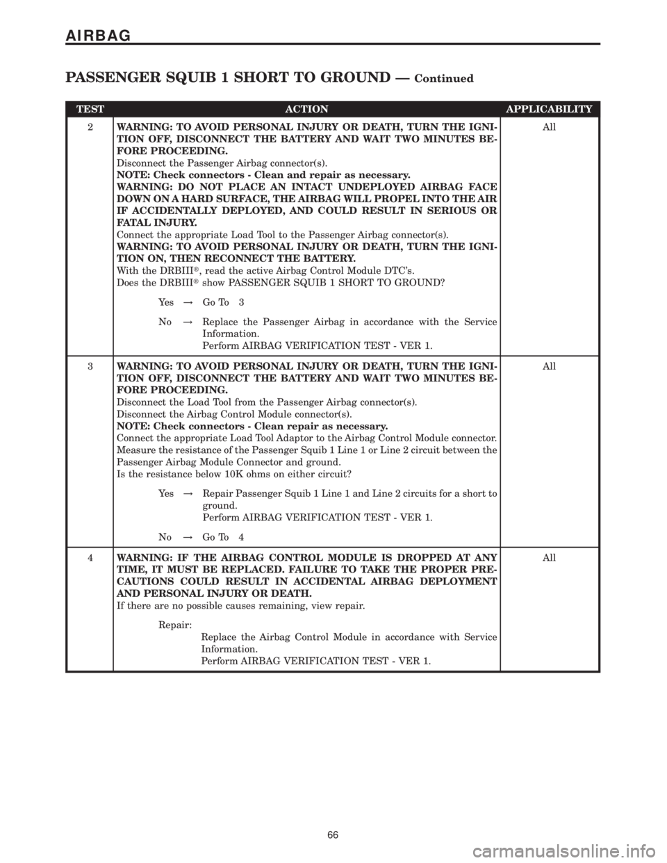
TEST ACTION APPLICABILITY
2WARNING: TO AVOID PERSONAL INJURY OR DEATH, TURN THE IGNI-
TION OFF, DISCONNECT THE BATTERY AND WAIT TWO MINUTES BE-
FORE PROCEEDING.
Disconnect the Passenger Airbag connector(s).
NOTE: Check connectors - Clean and repair as necessary.
WARNING: DO NOT PLACE AN INTACT UNDEPLOYED AIRBAG FACE
DOWN ON A HARD SURFACE, THE AIRBAG WILL PROPEL INTO THE AIR
IF ACCIDENTALLY DEPLOYED, AND COULD RESULT IN SERIOUS OR
FATAL INJURY.
Connect the appropriate Load Tool to the Passenger Airbag connector(s).
WARNING: TO AVOID PERSONAL INJURY OR DEATH, TURN THE IGNI-
TION ON, THEN RECONNECT THE BATTERY.
With the DRBIIIt, read the active Airbag Control Module DTC's.
Does the DRBIIItshow PASSENGER SQUIB 1 SHORT TO GROUND?All
Ye s!Go To 3
No!Replace the Passenger Airbag in accordance with the Service
Information.
Perform AIRBAG VERIFICATION TEST - VER 1.
3WARNING: TO AVOID PERSONAL INJURY OR DEATH, TURN THE IGNI-
TION OFF, DISCONNECT THE BATTERY AND WAIT TWO MINUTES BE-
FORE PROCEEDING.
Disconnect the Load Tool from the Passenger Airbag connector(s).
Disconnect the Airbag Control Module connector(s).
NOTE: Check connectors - Clean repair as necessary.
Connect the appropriate Load Tool Adaptor to the Airbag Control Module connector.
Measure the resistance of the Passenger Squib 1 Line 1 or Line 2 circuit between the
Passenger Airbag Module Connector and ground.
Is the resistance below 10K ohms on either circuit?All
Ye s!Repair Passenger Squib 1 Line 1 and Line 2 circuits for a short to
ground.
Perform AIRBAG VERIFICATION TEST - VER 1.
No!Go To 4
4WARNING: IF THE AIRBAG CONTROL MODULE IS DROPPED AT ANY
TIME, IT MUST BE REPLACED. FAILURE TO TAKE THE PROPER PRE-
CAUTIONS COULD RESULT IN ACCIDENTAL AIRBAG DEPLOYMENT
AND PERSONAL INJURY OR DEATH.
If there are no possible causes remaining, view repair.All
Repair:
Replace the Airbag Control Module in accordance with Service
Information.
Perform AIRBAG VERIFICATION TEST - VER 1.
66
AIRBAG
PASSENGER SQUIB 1 SHORT TO GROUND ÐContinued
Page 80 of 2305
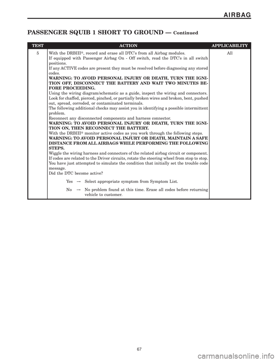
TEST ACTION APPLICABILITY
5 With the DRBIIIt, record and erase all DTC's from all Airbag modules.
If equipped with Passenger Airbag On - Off switch, read the DTC's in all switch
positions.
If any ACTIVE codes are present they must be resolved before diagnosing any stored
codes.
WARNING: TO AVOID PERSONAL INJURY OR DEATH, TURN THE IGNI-
TION OFF, DISCONNECT THE BATTERY AND WAIT TWO MINUTES BE-
FORE PROCEEDING.
Using the wiring diagram/schematic as a guide, inspect the wiring and connectors.
Look for chaffed, pierced, pinched, or partially broken wires and broken, bent, pushed
out, spread, corroded, or contaminated terminals.
The following additional checks may assist you in identifying a possible intermittent
problem.
Reconnect any disconnected components and harness connector.
WARNING: TO AVOID PERSONAL INJURY OR DEATH, TURN THE IGNI-
TION ON, THEN RECONNECT THE BATTERY.
With the DRBIIItmonitor active codes as you work through the following steps.
WARNING: TO AVOID PERSONAL INJURY OR DEATH, MAINTAIN A SAFE
DISTANCE FROM ALL AIRBAGS WHILE PERFORMING THE FOLLOWING
STEPS.
Wiggle the wiring harness and connectors of the related airbag circuit or component.
If codes are related to the Driver circuits, rotate the steering wheel from stop to stop.
You have just attempted to simulate the condition that initially set the trouble code
message.
Did the DTC become active?All
Ye s!Select appropriate symptom from Symptom List.
No!No problem found at this time. Erase all codes before returning
vehicle to customer.
67
AIRBAG
PASSENGER SQUIB 1 SHORT TO GROUND ÐContinued
Page 83 of 2305
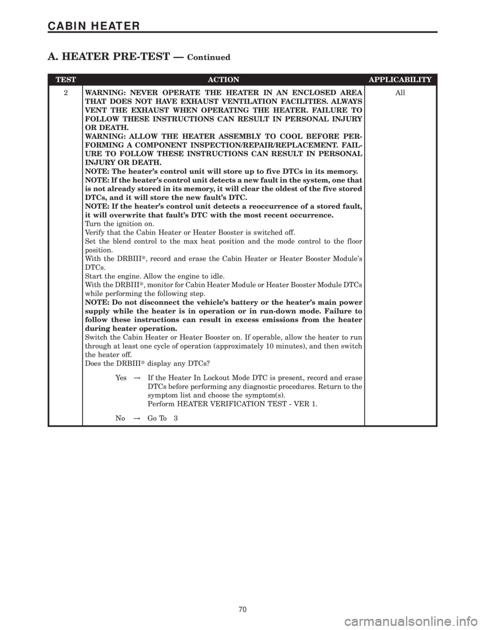
TEST ACTION APPLICABILITY
2WARNING: NEVER OPERATE THE HEATER IN AN ENCLOSED AREA
THAT DOES NOT HAVE EXHAUST VENTILATION FACILITIES. ALWAYS
VENT THE EXHAUST WHEN OPERATING THE HEATER. FAILURE TO
FOLLOW THESE INSTRUCTIONS CAN RESULT IN PERSONAL INJURY
OR DEATH.
WARNING: ALLOW THE HEATER ASSEMBLY TO COOL BEFORE PER-
FORMING A COMPONENT INSPECTION/REPAIR/REPLACEMENT. FAIL-
URE TO FOLLOW THESE INSTRUCTIONS CAN RESULT IN PERSONAL
INJURY OR DEATH.
NOTE: The heater's control unit will store up to five DTCs in its memory.
NOTE: If the heater's control unit detects a new fault in the system, one that
is not already stored in its memory, it will clear the oldest of the five stored
DTCs, and it will store the new fault's DTC.
NOTE: If the heater's control unit detects a reoccurrence of a stored fault,
it will overwrite that fault's DTC with the most recent occurrence.
Turn the ignition on.
Verify that the Cabin Heater or Heater Booster is switched off.
Set the blend control to the max heat position and the mode control to the floor
position.
With the DRBIIIt, record and erase the Cabin Heater or Heater Booster Module's
DTCs.
Start the engine. Allow the engine to idle.
With the DRBIIIt, monitor for Cabin Heater Module or Heater Booster Module DTCs
while performing the following step.
NOTE: Do not disconnect the vehicle's battery or the heater's main power
supply while the heater is in operation or in run-down mode. Failure to
follow these instructions can result in excess emissions from the heater
during heater operation.
Switch the Cabin Heater or Heater Booster on. If operable, allow the heater to run
through at least one cycle of operation (approximately 10 minutes), and then switch
the heater off.
Does the DRBIIItdisplay any DTCs?All
Ye s!If the Heater In Lockout Mode DTC is present, record and erase
DTCs before performing any diagnostic procedures. Return to the
symptom list and choose the symptom(s).
Perform HEATER VERIFICATION TEST - VER 1.
No!Go To 3
70
CABIN HEATER
A. HEATER PRE-TEST ÐContinued
Page 86 of 2305
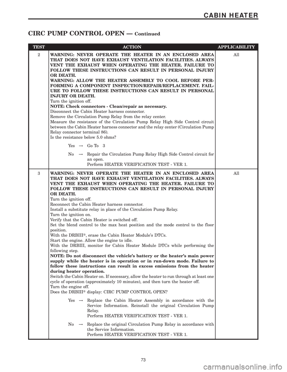
TEST ACTION APPLICABILITY
2WARNING: NEVER OPERATE THE HEATER IN AN ENCLOSED AREA
THAT DOES NOT HAVE EXHAUST VENTILATION FACILITIES. ALWAYS
VENT THE EXHAUST WHEN OPERATING THE HEATER. FAILURE TO
FOLLOW THESE INSTRUCTIONS CAN RESULT IN PERSONAL INJURY
OR DEATH.
WARNING: ALLOW THE HEATER ASSEMBLY TO COOL BEFORE PER-
FORMING A COMPONENT INSPECTION/REPAIR/REPLACEMENT. FAIL-
URE TO FOLLOW THESE INSTRUCTIONS CAN RESULT IN PERSONAL
INJURY OR DEATH.
Turn the ignition off.
NOTE: Check connectors - Clean/repair as necessary.
Disconnect the Cabin Heater harness connector.
Remove the Circulation Pump Relay from the relay center.
Measure the resistance of the Circulation Pump Relay High Side Control circuit
between the Cabin Heater harness connector and the relay center (Circulation Pump
Relay connector terminal 86).
Is the resistance below 5.0 ohms?All
Ye s!Go To 3
No!Repair the Circulation Pump Relay High Side Control circuit for
an open.
Perform HEATER VERIFICATION TEST - VER 1.
3WARNING: NEVER OPERATE THE HEATER IN AN ENCLOSED AREA
THAT DOES NOT HAVE EXHAUST VENTILATION FACILITIES. ALWAYS
VENT THE EXHAUST WHEN OPERATING THE HEATER. FAILURE TO
FOLLOW THESE INSTRUCTIONS CAN RESULT IN PERSONAL INJURY
OR DEATH.
Turn the ignition off.
Reconnect the Cabin Heater harness connector.
Install a substitute relay in place of the Circulation Pump Relay.
Turn the ignition on.
Verify that the Cabin Heater is switched off.
Set the blend control to the max heat position and the mode control to the floor
position.
With the DRBIIIt, erase the Cabin Heater Module's DTCs.
Start the engine. Allow the engine to idle.
With the DRBIII, monitor for Cabin Heater Module DTCs while performing the
following step.
NOTE: Do not disconnect the vehicle's battery or the heater's main power
supply while the heater is in operation or in run-down mode. Failure to
follow these instructions can result in excess emissions from the heater
during heater operation.
Switch the Cabin Heater on. If necessary, allow the heater to run through at least one
cycle of operation (approximately 10 minutes), and then turn the heater off.
Turn the engine off.
Does the DRBIIItdisplay: CIRC PUMP CONTROL OPEN?All
Ye s!Replace the Cabin Heater Assembly in accordance with the
Service Information. Reinstall the original Circulation Pump
Relay.
Perform HEATER VERIFICATION TEST - VER 1.
No!Replace the original Circulation Pump Relay in accordance with
the Service Information.
Perform HEATER VERIFICATION TEST - VER 1.
73
CABIN HEATER
CIRC PUMP CONTROL OPEN ÐContinued
Page 87 of 2305
Symptom:
CIRC PUMP CONTROL SHORTED
POSSIBLE CAUSES
CIRCULATION PUMP RELAY
CIRCULATION PUMP RELAY HIGH SIDE CONTROL CIRCUIT SHORTED TO GROUND
PUMP RELAY HIGH SIDE CONTROL CKT SHORTED TO PUMP RELAY GROUND CKT
CABIN HEATER CONTROL UNIT
TEST ACTION APPLICABILITY
1WARNING: NEVER OPERATE THE HEATER IN AN ENCLOSED AREA
THAT DOES NOT HAVE EXHAUST VENTILATION FACILITIES. ALWAYS
VENT THE EXHAUST WHEN OPERATING THE HEATER. FAILURE TO
FOLLOW THESE INSTRUCTIONS CAN RESULT IN PERSONAL INJURY
OR DEATH.
CAUTION: DO NOT PERFORM THIS TEST UNLESS DIRECTED HERE BY
THE HEATER PRE-TEST. ALWAYS PERFORM THE HEATER PRE-TEST
PRIOR TO PERFORMING ANY OTHER TEST FOR THE RESULT TO BE
VALID.
Turn the ignition off.
Install a substitute relay in place of the Circulation Pump Relay.
Turn the ignition on.
Verify that the Cabin Heater is switched off.
Set the blend control to the max heat position and the mode control to the floor
position.
With the DRBIIIt, erase the Cabin Heater Module's DTCs.
Start the engine. Allow the engine to idle.
With the DRBIII, monitor for Cabin Heater Module DTCs while performing the
following step.
NOTE: Do not disconnect the vehicle's battery or the heater's main power
supply while the heater is in operation or in run-down mode. Failure to
follow these instructions can result in excess emissions from the heater
during heater operation.
Switch the Cabin Heater on. If necessary, allow the heater to run through at least one
cycle of operation (approximately 10 minutes), and then switch the heater off.
Turn the engine off.
Does the DRBIIItdisplay: CIRC PUMP CONTROL SHORTED?All
Ye s!Go To 2
No!Replace the original Circulation Pump Relay in accordance with
the Service Information.
Perform HEATER VERIFICATION TEST - VER 1.
74
CABIN HEATER
Page 94 of 2305
Symptom:
DOSING PUMP SHORTED
POSSIBLE CAUSES
DOSING PUMP SHORTED TO GROUND
DOSING PUMP CONTROL CIRCUIT SHORTED TO GROUND CIRCUIT
DOSING PUMP CONTROL CIRCUIT SHORTED TO GROUND
CABIN HEATER OR HEATER BOOSTER CONTROL UNIT
TEST ACTION APPLICABILITY
1WARNING: NEVER OPERATE THE HEATER IN AN ENCLOSED AREA
THAT DOES NOT HAVE EXHAUST VENTILATION FACILITIES. ALWAYS
VENT THE EXHAUST WHEN OPERATING THE HEATER. FAILURE TO
FOLLOW THESE INSTRUCTIONS CAN RESULT IN PERSONAL INJURY
OR DEATH.
WARNING: ALLOW THE HEATER ASSEMBLY TO COOL BEFORE PER-
FORMING A COMPONENT INSPECTION/REPAIR/REPLACEMENT. FAIL-
URE TO FOLLOW THESE INSTRUCTIONS CAN RESULT IN PERSONAL
INJURY OR DEATH.
CAUTION: DO NOT PERFORM THIS TEST UNLESS DIRECTED HERE BY
THE HEATER PRE-TEST. ALWAYS PERFORM THE HEATER PRE-TEST
PRIOR TO PERFORMING ANY OTHER TEST FOR THE RESULT TO BE
VALID.
Turn the ignition off.
NOTE: Check connectors - Clean/repair as necessary.
Disconnect the Dosing Pump harness connector.
Turn the ignition on.
Verify that the Cabin Heater or Heater Booster is switched off.
Set the blend control to the max heat position and the mode control to the floor
position.
With the DRBIIIt, erase the Cabin Heater or Heater Booster Module's DTCs.
Start the engine. Allow the engine to idle.
With the DRBIII, monitor for Cabin Heater or Heater Booster Module DTCs while
performing the following step.
NOTE: Do not disconnect the vehicle's battery or the heater's main power
supply while the heater is in operation or in run-down mode. Failure to
follow these instructions can result in excess emissions from the heater
during heater operation.
Switch the Cabin Heater or Heater Booster on. If necessary, allow the heater to run
through at least one cycle of operation (approximately 10 minutes), and then switch
the heater off.
Turn the engine off.
Does the DRBIIItdisplay: DOSING PUMP HIGH OR OPEN?All
Ye s!Replace the Dosing Pump in accordance with the Service Infor-
mation.
Perform HEATER VERIFICATION TEST - VER 1.
No!Go To 2
81
CABIN HEATER
Page 95 of 2305
TEST ACTION APPLICABILITY
2WARNING: NEVER OPERATE THE HEATER IN AN ENCLOSED AREA
THAT DOES NOT HAVE EXHAUST VENTILATION FACILITIES. ALWAYS
VENT THE EXHAUST WHEN OPERATING THE HEATER. FAILURE TO
FOLLOW THESE INSTRUCTIONS CAN RESULT IN PERSONAL INJURY
OR DEATH.
WARNING: ALLOW THE HEATER ASSEMBLY TO COOL BEFORE PER-
FORMING A COMPONENT INSPECTION/REPAIR/REPLACEMENT. FAIL-
URE TO FOLLOW THESE INSTRUCTIONS CAN RESULT IN PERSONAL
INJURY OR DEATH.
Turn the ignition off.
Disconnect the battery in accordance with the Service information.
NOTE: Check connectors - Clean/repair as necessary.
Disconnect the Cabin Heater or Heater Booster harness connector.
NOTE: Check connectors - Clean/repair as necessary.
Disconnect the Dosing Pump harness connector.
Measure the resistance between the Dosing Pump Control circuit and the Ground
circuit in the Dosing Pump harness connector.
Is the resistance below 10K ohms?All
Ye s!Repair the Dosing Pump Control circuit for a short to the Ground
circuit.
Perform HEATER VERIFICATION TEST - VER 1.
No!Go To 3
3WARNING: NEVER OPERATE THE HEATER IN AN ENCLOSED AREA
THAT DOES NOT HAVE EXHAUST VENTILATION FACILITIES. ALWAYS
VENT THE EXHAUST WHEN OPERATING THE HEATER. FAILURE TO
FOLLOW THESE INSTRUCTIONS CAN RESULT IN PERSONAL INJURY
OR DEATH.
WARNING: ALLOW THE HEATER ASSEMBLY TO COOL BEFORE PER-
FORMING A COMPONENT INSPECTION/REPAIR/REPLACEMENT. FAIL-
URE TO FOLLOW THESE INSTRUCTIONS CAN RESULT IN PERSONAL
INJURY OR DEATH.
Turn the ignition off.
Disconnect the battery in accordance with the Service information.
NOTE: Check connectors - Clean/repair as necessary.
Disconnect the Cabin Heater or Heater Booster harness connector.
NOTE: Check connectors - Clean/repair as necessary.
Disconnect the Dosing Pump harness connector.
Measure the resistance between ground and the Dosing Pump Control circuit.
Is the resistance below 10K ohms?All
Ye s!Repair the Dosing Pump Control circuit for a short to ground.
Perform HEATER VERIFICATION TEST - VER 1.
No!Replace the Cabin Heater Assembly or Heater Booster Assembly
in accordance with the Service Information.
Perform HEATER VERIFICATION TEST - VER 1.
82
CABIN HEATER
DOSING PUMP SHORTED ÐContinued
Page 97 of 2305
TEST ACTION APPLICABILITY
2WARNING: NEVER OPERATE THE HEATER IN AN ENCLOSED AREA
THAT DOES NOT HAVE EXHAUST VENTILATION FACILITIES. ALWAYS
VENT THE EXHAUST WHEN OPERATING THE HEATER. FAILURE TO
FOLLOW THESE INSTRUCTIONS CAN RESULT IN PERSONAL INJURY
OR DEATH.
WARNING: ALLOW THE HEATER ASSEMBLY TO COOL BEFORE PER-
FORMING A COMPONENT INSPECTION/REPAIR/REPLACEMENT. FAIL-
URE TO FOLLOW THESE INSTRUCTIONS CAN RESULT IN PERSONAL
INJURY OR DEATH.
Turn the ignition off.
NOTE: Check connectors - Clean/repair as necessary.
Disconnect the Cabin Heater harness connector.
Remove the Fan Stage 1 Relay from the relay center.
Measure the resistance of the Fan Stage 1 Relay High Side Control circuit between
the Cabin Heater harness connector and the relay center (Fan Stage 1 Relay
connector terminal 86).
Is the resistance below 5.0 ohms?All
Ye s!Go To 3
No!Repair the Fan Stage 1 Relay High Side Control circuit for an
open.
Perform HEATER VERIFICATION TEST - VER 1.
3WARNING: NEVER OPERATE THE HEATER IN AN ENCLOSED AREA
THAT DOES NOT HAVE EXHAUST VENTILATION FACILITIES. ALWAYS
VENT THE EXHAUST WHEN OPERATING THE HEATER. FAILURE TO
FOLLOW THESE INSTRUCTIONS CAN RESULT IN PERSONAL INJURY
OR DEATH.
Turn the ignition off.
Reconnect the Cabin Heater harness connector.
Install a substitute relay in place of the Fan Stage 1 Relay.
Turn the ignition on.
Verify that the Cabin Heater is switched off.
Set the blend control to the max heat position and the mode control to the floor
position.
With the DRBIIIt, erase the Cabin Heater Module's DTCs.
Start the engine. Allow the engine to idle.
With the DRBIII, monitor for Cabin Heater Module DTCs while performing the
following step.
NOTE: Do not disconnect the vehicle's battery or the heater's main power
supply while the heater is in operation or in run-down mode. Failure to
follow these instructions can result in excess emissions from the heater
during heater operation.
Switch the Cabin Heater on. If necessary, allow the heater to run through at least one
cycle of operation (approximately 10 minutes), and then switch the heater off.
Turn the engine off.
Does the DRBIIItdisplay: FAN STAGE 1 RELAY CONTROL OPEN?All
Ye s!Replace the Cabin Heater Assembly in accordance with the
Service Information. Reinstall the original Fan Stage 1 Relay.
Perform HEATER VERIFICATION TEST - VER 1.
No!Replace the original Fan Stage 1 Relay in accordance with the
Service Information.
Perform HEATER VERIFICATION TEST - VER 1.
84
CABIN HEATER
FAN STAGE 1 RELAY CONTROL OPEN ÐContinued